

Question: P8-2: A digital system is modelled by the rtl-ASMchart given in Fig. P8-2a. (a) Obtain the fbd of the DU. Use the diagram template given
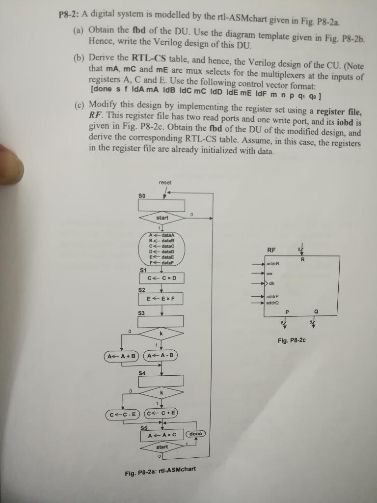
P8-2: A digital system is modelled by the rtl-ASMchart given in Fig. P8-2a. (a) Obtain the fbd of the DU. Use the diagram template given in Fig. P8-2b. Hence, write the Verilog design of this DU. (b) Derive the RTL-CS table, and hence, the Verilog design of the CU. (Note that mA, mc and mE are mux selects for the multiplexers at the inputs of registers A, C and E. Use the following control vector format: [done s f IdA mA IdB ldc mc Id IdE mE IdF mnp 91 qo] (c) Modify this design by implementing the register set using a register file, RF. This register file has two read ports and one write port, and its iobd is given in Fig. P8-2c. Obtain the fbd of the DU of the modified design, and derive the corresponding RTL-CS table. Assume, in this case, the registers in the register file are already initialized with data. reset SO 0 start RF Adata data Cdatac Ddata Edata E FdataF S1 CECXD R addrR cik S2 E EXF addrP addra S3 P 0 Fig. P8-2c A+ A+B AA-B 54 k CC-E C+ C+E ALANC done start Fig. P8-2a: Iti-ASMchart P8-2: A digital system is modelled by the rtl-ASMchart given in Fig. P8-2a. (a) Obtain the fbd of the DU. Use the diagram template given in Fig. P8-2b. Hence, write the Verilog design of this DU. (b) Derive the RTL-CS table, and hence, the Verilog design of the CU. (Note that mA, mc and mE are mux selects for the multiplexers at the inputs of registers A, C and E. Use the following control vector format: [done s f IdA mA IdB ldc mc Id IdE mE IdF mnp 91 qo] (c) Modify this design by implementing the register set using a register file, RF. This register file has two read ports and one write port, and its iobd is given in Fig. P8-2c. Obtain the fbd of the DU of the modified design, and derive the corresponding RTL-CS table. Assume, in this case, the registers in the register file are already initialized with data. reset SO 0 start RF Adata data Cdatac Ddata Edata E FdataF S1 CECXD R addrR cik S2 E EXF addrP addra S3 P 0 Fig. P8-2c A+ A+B AA-B 54 k CC-E C+ C+E ALANC done start Fig. P8-2a: Iti-ASMchart
Step by Step Solution
There are 3 Steps involved in it

Get step-by-step solutions from verified subject matter experts