

Question: testbench.sv `default_nettype none module tb_vend; wire dispense; wire [2:0] change; reg quarter, loonie, toonie, clk; VendingMachineController dut(quarter, loonie, toonie, clk, dispense, change); initial begin $dumpfile(dump.vcd);
![testbench.sv `default_nettype none module tb_vend; wire dispense; wire [2:0] change; reg](https://dsd5zvtm8ll6.cloudfront.net/si.experts.images/questions/2024/09/66f2f89de7687_38966f2f89d551a1.jpg)
testbench.sv
`default_nettype none
module tb_vend; wire dispense; wire [2:0] change; reg quarter, loonie, toonie, clk; VendingMachineController dut(quarter, loonie, toonie, clk, dispense, change); initial begin $dumpfile("dump.vcd"); $dumpvars(0, dut);
$display(" -- Testing only quarters -- "); quarter
$display(" -- Testing only Loonies -- "); loonie
$display(" -- Testing only Toonies -- "); toonie
$display(" -- Testing Loonies + Quarters -- "); quarter
$display(" -- Testing Toonies + Quarters -- "); quarter
task pulseClock; begin #1 clk
task assertEquals; input val; input eq; begin if ( val == eq ) $display("[TEST][PASSED] Dispensed: %b", val); else $display("[TEST][FAILED] Dispensed: %b, expected %b", val, eq); end endtask
task assertEquals3Bit; input [2:0] val; input [2:0] eq; begin if ( val == eq ) $display("[TEST][PASSED] Change: %d", val); else $display("[TEST][FAILED] Change: %d, expected %d", val, eq); end endtask endmodule
designbbench.sv
// Code your design here
`default_nettype none
module VendingMachineController(
input quarter, input loonie, input toonie, input clk, output dispense, output [2:0] change );
endmodule
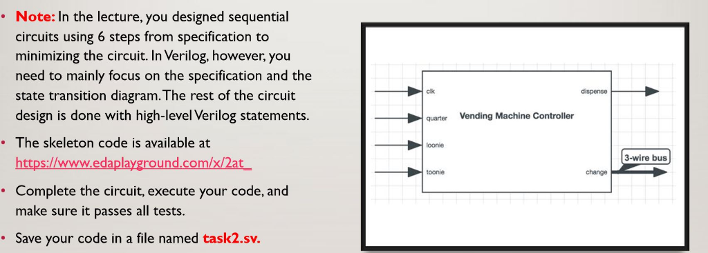
Using previous knowledge of sequential circuits, you will now construct a vending machine controller according to the following specifications The circuit has four inputs: clk, quarter, loonie, and toonie. The controller also has two outputs: change and dispense. Change is a 3-bit bus which outputs a binary number indicating the number of quarters to dispense. Dispense is a single on/off wire. . You must implement the controller based on the following properties l) The item (and change, if any) is dispensed when at least $I has been inserted into the machine. 2) The change output outputs a binary number indicating the number of quarters to dispense. 3) The dispense and change signals are set on the same clock tick that the amount is met. 4) At any given clock tick, only one coin can be entered. Note: In the lecture, you designed sequential circuits using 6 steps from specification to minimizing the circuit. In Verilog, however, you need to mainly focus on the specification and the state transition diagram.The rest of the circuit design is done with high-level Verilog statements. clk dispense quarterVending Machine Controller The skeleton code is available at https://www.edaplayground.com/x/2at loonie 3-wire bus oonie hange Complete the circuit, execute your code, and make sure it passes all tests. Save your code in a file named task2.sv. Using previous knowledge of sequential circuits, you will now construct a vending machine controller according to the following specifications The circuit has four inputs: clk, quarter, loonie, and toonie. The controller also has two outputs: change and dispense. Change is a 3-bit bus which outputs a binary number indicating the number of quarters to dispense. Dispense is a single on/off wire. . You must implement the controller based on the following properties l) The item (and change, if any) is dispensed when at least $I has been inserted into the machine. 2) The change output outputs a binary number indicating the number of quarters to dispense. 3) The dispense and change signals are set on the same clock tick that the amount is met. 4) At any given clock tick, only one coin can be entered. Note: In the lecture, you designed sequential circuits using 6 steps from specification to minimizing the circuit. In Verilog, however, you need to mainly focus on the specification and the state transition diagram.The rest of the circuit design is done with high-level Verilog statements. clk dispense quarterVending Machine Controller The skeleton code is available at https://www.edaplayground.com/x/2at loonie 3-wire bus oonie hange Complete the circuit, execute your code, and make sure it passes all tests. Save your code in a file named task2.sv
Step by Step Solution
There are 3 Steps involved in it

Get step-by-step solutions from verified subject matter experts