

The single-phase, two-wire lossless line in Figure 13.3 has a series inductance (mathrm{L}=(1 / 3) times 10^{-6}
Question:
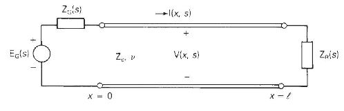
The single-phase, two-wire lossless line in Figure 13.3 has a series inductance \(\mathrm{L}=(1 / 3) \times 10^{-6} \mathrm{H} / \mathrm{m}\), a shunt capacitance \(\mathrm{C}=(1 / 3) \times 10^{-10} \mathrm{~F} / \mathrm{m}\), and a \(50-\mathrm{km}\) line length. The source voltage at the sending end is a step \(\mathrm{e}_{\mathrm{G}}(t)=100 \mathrm{u}_{-1}(t) \mathrm{kV}\) with \(\mathrm{Z}_{\mathrm{G}}(s)=100 \Omega\). The receiving-end load consists of a \(100-\Omega\) resistor in parallel with a \(2-\mathrm{mH}\) inductor. The line and load are initially unenergized. Determine
(a) the characteristic impedance in ohms, the wave velocity in \(\mathrm{m} / \mathrm{s}\), and the transit time in \(\mathrm{ms}\) for this line;
(b) the sending-and receiving-end voltage reflection coefficients in perunit;
(c) the Laplace transform of the receiving-end current, \(I_{R}(s)\); and
(d) the receiving-end current \(i_{\mathrm{R}}(t)\) as a function of time.
Figure 13.3
Step by Step Answer:


Power System Analysis And Design
ISBN: 9781305632134
6th Edition
Authors: J. Duncan Glover, Thomas Overbye, Mulukutla S. Sarma
