New Semester
Started
Get
50% OFF
Study Help!
--h --m --s
Claim Now
Question Answers
Textbooks
Find textbooks, questions and answers
Oops, something went wrong!
Change your search query and then try again
S
Books
FREE
Study Help
Expert Questions
Accounting
General Management
Mathematics
Finance
Organizational Behaviour
Law
Physics
Operating System
Management Leadership
Sociology
Programming
Marketing
Database
Computer Network
Economics
Textbooks Solutions
Accounting
Managerial Accounting
Management Leadership
Cost Accounting
Statistics
Business Law
Corporate Finance
Finance
Economics
Auditing
Tutors
Online Tutors
Find a Tutor
Hire a Tutor
Become a Tutor
AI Tutor
AI Study Planner
NEW
Sell Books
Search
Search
Sign In
Register
study help
computer science
signals and systems
Signals and Systems using MATLAB 2nd edition Luis Chaparro - Solutions
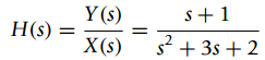
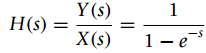
A sinc signal x(t) = sin(0.5t)/(πt)is passed through an ideal low-pass filter with a frequency response H(jΩ) = u(Ω + 0.5) − u(Ω − 0.5)(a) Find the Fourier transform X(Ω)and carefully plot it.(b) Find the output y(t) of the filter by calculating first Y(Ω). What is the
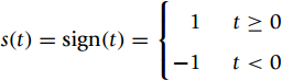
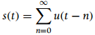
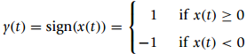
Consider the sign signal(a) Find the derivative of s(t) and use it to find S(Ω) = F(s(t)).(b) Find the magnitude and phase of S(Ω).(c) Use the equivalent expression s(t) = 2[u(t) ˆ’ 0.5] to get S(Ω). t > 0 t < 0 s(t) = sign(t) = -1
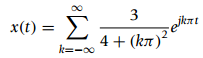
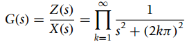
A periodic signal x(t) has a periodx1(t) = r(t) ˆ’ 2r(t ˆ’ 1) + r(t ˆ’ 2), T0 = 2(a) Find the Fourier series of z(t) = d2x(t)/dt2 using the Laplace transform. Then use the derivative property to find the Fourier trans-form of x(t).(b) To
Consider the following problems related to the modulation and power properties of the Fourier transform.(a) The carrier of an AM system is cos(10t), consider the following message signalsi. m(t) = cos(t)ii. m(t) = r(t) ˆ’ 2r(t ˆ’ 1) + r(t ˆ’ 2),
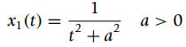
In the following problems we want to find the Fourier transform of the signals.(a) For the signalfind its Fourier transform by using the Fourier transform ofx(t) = 0.5e€“at u(t) ˆ’ 0.5eat u(ˆ’t), a > 0as a → 0.Use then Y(Ω) to determine the Fourier transform of the unit-step
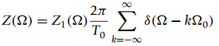
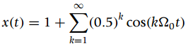
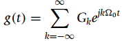
Use properties of the Fourier transform in the following problems.(a) Use the Fourier transform of cos(kΩ0t)to find the Fourier transform of a periodic signal x(t) with a Fourier series(b) Find the Fourier transform ofby considering the properties of the transform. x(t) = 1+(0.5)*
The derivative property can be used to simplify the computation of some Fourier transforms. Letx(t) = r(t) − 2r(t − 1) + r(t − 2)(a) Find and plot the second derivative with respect to tof x(t), y(t) = d2x(t)/dt2.(b) Find X(Ω) from Y(Ω)using the derivative property.(c) Verify the above
Find the Fourier transform of δ(t − τ) and use it to find the Fourier transforms of(a) δ(t − 1) + δ(t + 1).(b) cos(Ω0t).(c) sin(Ω0t).
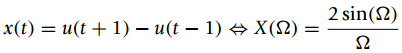
Starting with the Fourier transform pairand using no integration, indicate the properties of the Fourier transform that will allow you to compute the Fourier transform of the following signals (do not find the Fourier transforms):(a) x1(t) = ˆ’u(t + 2) + 2u(t) ˆ’ u(t
The Fourier transform of a signal x(t) isUse properties of the Fourier transform to(a) find the integral(b) Find the value x(0).(c) Let s=jΩ or Ω = (s/j), find X(s) and from it obtain x(t). %3D X(2) = 1+N? x(t)dt -0-
There are signals whose Fourier transforms cannot be found directly by either the integral definition or the Laplace transform. For instance, the sinc signalis one of them.(a) Let X(Ω) = A[u(Ω + Ω0) ˆ’ u(Ω €“
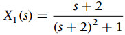
A causal signal x(t) having a Laplace transform with poles in the open-left s-plane (i.e., not including the jΩ-axis) has a Fourier transform that can be found from its Laplace transform. Consider the following signalsx1(t) = e−2t u(t), x2(t) =
As seen in the previous problem, the Fourier series is one of a possible class of representations in terms of orthonormal functions. Consider the case of the Walsh functions which are a set of rectangular pulse signals that are orthonormal in a finite time interval [0, 1]. These functions are such
We wish to approximate the triangular signal x(t), with a period x1(t) = r(t) − 2r(t − 1) + r(t − 2), by a Fourier series with a finite number of terms, let’s say 2N. This approximation should have 99% of the power of the triangular signal, use MATLAB to find the value of N.
Consider a full-wave rectifier that has as output a periodic signal x(t) of fundamental period T0= 1 and a period of it is given as(a) Obtain the Fourier coefficients Xk.(b) Suppose we pass x(t) through an ideal filter of transfer function H(s), determine the values of this filter at harmonic
The smoothness of a period deter-mines the way the magnitude line spectrum decays. Consider the following periodic signals x(t) and y(t) both of fundamental period T0 = 2sec., and with a period from 0 ≤ t ≤ T0 equal tox1(t) = u(t) − u(t − 1), y1(t) = r(t) − 2r(t − 1) + r(t − 2).Find
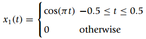
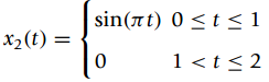
Rectifying a sinusoid provides a way to create a dc source. In this problem we consider the Fourier series of the full and the half-wave rectified signals. The full-wave rectified signal xf(t) has a fundamental period T0= 1 and its period from 0 to 1 isx1(t) = sin(Ï€ t)
The computation of the Fourier series coefficients is helped by the relation between the formula for these coefficients and the Laplace transform of a period of the periodic signal.(a) A periodic signal x(t) of period T0 = 2 sec., has as a period the signal x1(t) = u(t) − u(t − 1). Use the
Let x(t) = sin2(2πt), a periodic signal of fundamental period T0 = 0.5, and y(t) = |sin(2π t)|also periodic of the same fundamental period.(a) A trigonometric identity gives that x(t) = 0.5[1 − cos(4π t)]. Use this result to find its complex exponential Fourier series.(b) Use the Laplace
We want to use the Fourier series of a train of square pulses (done in the chapter) to compute the Fourier series of the triangular signal x(t)with a periodx1(t) = r(t) − 2r(t − 1) + r(t − 2)(a) Find the derivative of x(t)or y(t) = dx(t)/dt and carefully plot it. Plot also z(t) = y(t) +
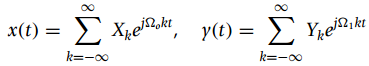
Consider the Fourier series of two periodic signals(a) Let Ω1 = Ω0, is z(t) = x(t) y(t) periodic? If so, what is its fundamental period and its Fourier series coefficients?(b) If Ω1 = 2Ω0, is w(t) = x(t) y(t) periodic? If so, what
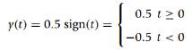
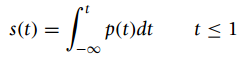
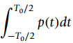
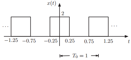
Consider the integral of the Fourier series of the pulse signal p(t) = x(t) ˆ’1 of period T0= 1, where x(t) is given in Figure 4.22.(a) Given that an integral of p(t) is the area under the curve, find and plot the functionindicate the values of s(t) for t = 0, 0.25, 0.5, 0.75, and 1.(b)
Given the Fourier series representation for a periodic signal x(t), we can compute derivatives of it just like with any other signal.(a) Consider the periodic train of pulses shown in Figure 4.22, compute its derivative y(t) = dx(t)/dt and carefully plot it. Find the Fourier series of
The following problems are about the steady state response of LTI systems due to periodic signals.(a) The transfer function of a LTI system isIf the input to this system is x(t) = 1 + cos(t + π/4) what is the output y(t) in the steady state.(b) The transfer function of a LTI
Consider the periodic signal x(t) shown in Figure 4.21.(a) Use the Laplace transform to compute the Fourier series coefficients Xk, k‰ 0 of x(t).(b) Suppose that to find the Fourier series of x(t) we consider finding its derivative, or g(t) = dx(t)/dt. Give an expression for
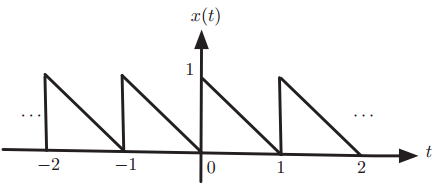
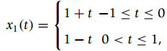
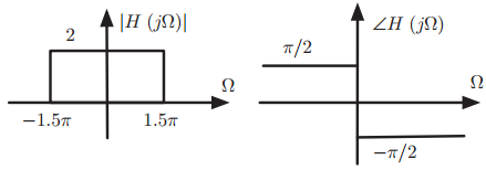
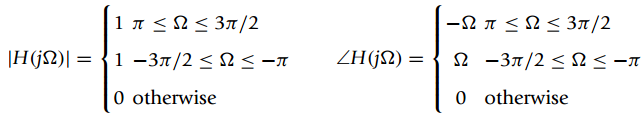
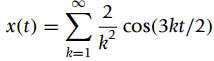
A periodic signal x(t), of fundamental frequency Ω0= π, has a periodThe signal x(t) is the input of an ideal low-pass filter with the frequency response H(jΩ) shown in Figure 4.20. Let y(t) be the output of the system.(a) Determtine the Fourier series
We are interested in designing a dc voltage source. To do so, we full-wave rectify an AC voltage to obtain the signal x(t) =|cos(πt)|,−∞(a) Specify the magnitude response |H(jΩ)|of the ideal low-pass filter so that only the dc component of x(t)is passed through. Let the phase response be
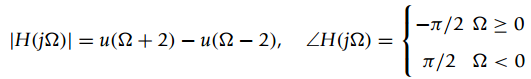
Consider the following problems related to filtering of periodic signals:(a) A periodic signal x(t)of fundamental frequency Ω0 = π/4 is the input of an ideal band-pass filter with the following frequency responseThe non-zero Fourier series coefficients of x(t)areX1 =
Consider a periodic signal x(t) with fundamental period T0 =1 and a period x1(t) = −0.5t[u(t) − u(t − 1)].(a) Consider the derivative g(t) = dx(t)/dt. Indicate if g(t) is periodic and if so give its fundamental period.(b) Find the Fourier series of g(t) and use it to find the
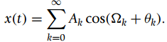
Consider the following problems related to steady state and frequency responses.(a) The input x(t)and the output y(t),ˆ’ˆžx(t) = 4 cos(2Ï€ t) + 8 sin(3Ï€ t), y(t) = ˆ’2 cos(2Ï€ t).Determine as much as possible about the frequency
A period of a periodic signal x(t)with fundamental period T0 = 2 isx1 (t) = cos(t) [u(t) − u(t − 2)].(a) Plot the signal x(t) and find the Fourier series coefficients {Xk} for x(t) using the integral equation.(b) Use the Laplace transform to find the Fourier series coefficients {Xk}.(c) After
Consider a periodic signalx(t) = 0.5 + 4 cos(2π t) − 8 cos(4π t) − ∞(a) Determine the fundamental frequency Ω0 of x(t).(b) Find the Fourier series coefficients {Xk} and carefully plot their magnitude, and phase spectra. According to the magnitude line
Let the Fourier series coefficients of a periodic signal x(t) of fundamental frequency Ω0 =2π/T0 be {Xk}. Consider the following functions of x(t).y(t) = 2x(t)−3, z(t) = x(t − 2) + x(t), w(t) = x(2t)Determine if y(t), z(t), and w(t) are periodic,
Suppose you have the Fourier series of two periodic signals x(t)and y(t)of fundamental periods T1 and T2, respectively. Let Xk and Yk be the Fourier series coefficients corresponding to x(t) and y(t).(a) If T1 =T2 what would be the Fourier series coefficients of z(t) = x(t) + y(t) in
Consider the following problems related to the exponential Fourier series.(a) The exponential Fourier series of a periodic signal x(t)of fundamental period T0 isi. Determine the value of the fundamental period T0.ii. What is the average or dc value of x(t)?iii. Is x(t)even, odd, or neither
Let a periodic signal x(t)with a fundamental frequency Ω0 = 2π have a periodx1(t) = t[u (t) − u(t − 1)](a) Plot x(t), and indicate its fundamental period T0.(b) Compute the Fourier series coefficients of x(t)using their integral definition.(c) Use the Laplace transform to
Find the complex exponential Fourier series for the following signals. In each case plot the magnitude and phase line spectra for k ≥ 0. (i)x1(i) x1(t) = cos(5t + 45°), (ii) x2(t) = sin2 (t),(iii) x3 (t) = cos(3t) + cos(5t)]
A periodic signal x(t) has a fundamental frequency Ω0 = 1 and a period of it isx1(t) = u(t) − 2u(t − π) + u(t − 2π)(a) Find the Fourier series coefficients {Xk} of x(t) using their integral definition.(b) Use the Laplace transform to find the Fourier series coefficients {Xk} of
Consider the following problems related to periodicity and Fourier series:(a) For the signalsx1(t) = 1 + cos(2Ï€ t) ˆ’ cos(6Ï€ t),x2(t) = 1 + cos(2Ï€ t) ˆ’ cos(6t) ˆ’ˆž < t < ˆži. Determine
The input-output equation for an analog averager islet x(t) = ejΩ0t. Since the system is LTI then the output should be y(t) = ejΩ0t H(jΩ0).(a) Find the integral for the given input and then compare it with the above equation to find H(jΩ0), the
The eigenfunction property is only valid for LTI systems. Consider the cases of non-linear and of time-varying systems.(a) A system represented by the input-output equation y(t) = x2(t) is non-linear. Let the input be x(t) = ejπt/4 find the corresponding system output y(t). Does the
Consider a negative feedback system used to control a plant with transfer functionG(s) = 1/(s(s + 1)(s + 2)).The output y(t)of the feedback system is connected via a sensor with transfer function H(s) = 1 to a differentiator where the reference signal x(t) is also connected. The output of the
When the numerator or denominator are given in a factorized form, we need to multiply polynomials. Although this can be done by hand, MATLAB provides the function convthat computes the coefficients of the polynomial resulting from the product of two polynomials.(a) Use helpin MATLAB to find
In the generation of dc from ac voltage, the ”half-wave” rectified signal is an important part. Suppose the ac voltage is x(t) = sin(2π t) u(t) and y(t) is the half-wave rectified signal.(a) Let y1(t) be the period of y(t) between 0 ≤ t ≤ 1. Show that y1(t) can be written equivalently
Consider the convolution of a pulse x(t) = u(t + 0.5) − u(t − 0.5) with itself many times. Use MATLAB for the calculations and the plotting.(a) Consider the result for N = 2 of these convolutions, i.e., y2(t) = (x∗x) (t) Find Y2(s) = L[y2(t)] using the convolution property of the Laplace
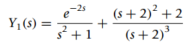
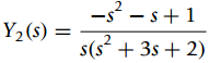
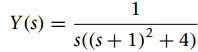
Consider the following functions Yi(s) = L[yi(t)], i = 1, 2 and 3,where {yi(t), i = 1, 2, 3} are the complete responses of differential equations with zero initial conditions.(a) For each of these functions determine the corresponding differential equation, if all of them have as input x(t) =
An analog averager can be represented by the differential equationwhere y(t)is its output and x(t)the input.(a) If the input-output equation of the averager isShow how to obtain the above differential equation and that y(t)is the solution of the differential equation.(b) If x(t) =
The type of transient you get in a second-order system depends on the location of the poles of the system. The transfer function of the second-order system isand let the input be x(t) = u(t).(a) Let the coefficients of the denominator of H(s) be b1 = 5, b0 = 6, find the response y(t). Use
Let Y(s) = L[y(t)] be the Laplace transform of the solution of a second-order differential equation representing a system with input x(t) and some initial conditions,(a) Find the zero-state response (response due to the input only with zero initial conditions) for x(t) = u(t).(b) Find the
The following function Y(s) = L[y(t)] is obtained applying the Laplace transform to a differential equation representing a system with non-zero initial conditions and input x(t), with Laplace transform X(s)(a) Find the differential equation in y(t) and x(t) representing the
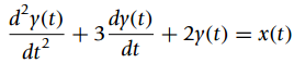
One of the uses of the Laplace trans-form is the solution of differential equations.(a) Suppose you are given the ordinary differential equation that rep-resents a LTI system,y(2)(t) + 0.5y(1) (t) + 0.15y(t) = x(t), t ≥ 0where y(t) is the output and x(t) is the input of the system, y(1)(t)
The poles corresponding to the Laplace transform X(s)of a signal x(t) are p1,2 = ˆ’3 ±jÏ€/2 and p3=0.(a) Within some constants, give a general form of the signal x(t).(b) Letfrom the location of the poles, obtain a general form for x(t). Use MATLAB to find
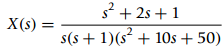
Consider the following inverse Laplace problems:(a) Use MATLAB to compute the inverse Laplace transform ofDetermine the value of x(t)in the steady state. How would you be able to obtain this value without computing the inverse? Explain.(b) Find the inverse x(t)ofUse MATLAB to plot x(t)and
Consider the following inverse Laplace transform problems.(a) Given the Laplace transformwhich is not proper, determine the amplitude of the δ(t)and dδ(t)/dt terms in the inverse signal y(t).(b) Find the inverse Laplace transform ofCan you use the initial-value
The following problems consider approaches to stabilize an unstable system.(a) An unstable system can be stabilized by using negative feedback with a gain Kin the feedback loop. For instance consider an unstable system with transfer functionwhich has a pole in the right-hand s-plane making the
There are two types of feedback, negative and positive. In this problem we explore their difference.(a) Consider negative feedback. Suppose you have a system with transfer function H(s) = Y(s)/E(s) where E(s) = C(s) − Y(s), and C(s)and Y(s) are the transforms of the feedback system’s
To see the effect of the zeros on the complete response of a system, sup-pose you have a system with a transfer function(a) Find and plot the poles and zeros of H(s). Is this BIBO stable?(b) Find the frequency Ω0 of the input x(t) = 2 cos(Ω0 t) u(t) such that
The input/output equation for an analog averager is given by the convolution integralwhere x(t)is the input and y(t)the output.(a) Change the above equation to determine the impulse response h(t).(b) Graphically determine the output y(t) corresponding to a pulse input x(t) = u(t)
The steady-state solution of stable systems is due to simple poles in the jΩ axis of the s-plane coming from the input. Suppose the transfer function of the system is(a) Find the poles and zeros of H(s) and plot them in the s-plane. Find then the corresponding impulse response
The transfer function of a BIBO stable and causal system has poles only on the open left-hand s-plane (excluding the jΩ axis).(a) Let the transfer function of a system beand let the poles of X(s)be on the left-hand s-plane. Find limt†’ˆžy(t). Determine if
In convolution problems the impulse response h(t)of the system and the input x(t)are given and one is interested in finding the output of the system y(t). The so-called €œdeconvolution€ problem consists in giving two of x(t), h(t) and y(t) to find the other. For instance, the
Consider the following problems related to the convolution integral.(a) The impulse response of a LTI system is h(t) = e−2tu(t) and the system input is a pulse x(t) = u(t) − u(t − 3). Find the output of the system y(t) by means of the convolution integral graphically and by means of the
Consider the following cases where we want to determine different types of responses.(a) The input to a LTI system is x(t) = u(t) ˆ’ 2u(t ˆ’ 1) + u(t ˆ’ 2) and the Laplace transform of the output is given bydetermine the impulse response of the
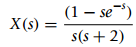
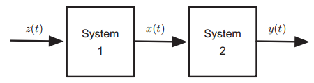
Consider the cascade of two LTI systems, see Figure 3.21, where the input of the cascade is z(t) and the output is y(t), while x(t)is the output of the first system and the input of the second system. The input to the cascaded systems is z(t) = (1 ˆ’ t) [u(t) ˆ’ u(t ˆ’
A wireless channel is represented by y(t) = αx(t − T) + α3x(t − 3T) where 0 < α < 1 is the attenuation and T the delay. The input is x(t) and the output y(t).(a) Find the impulse response h(t)of the channel.(b) Find the transfer function H(s), and its poles and zeros. Determine if
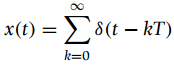
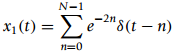
The impulse response of an LTI is h(t) = r(t) ˆ’ 2r(t ˆ’ 1) + r(t ˆ’ 2) and the input is a sequence of impulses(a) Find the system output y(t)as the convolution integral of x(t) and h(t), and plot it for T = 1 and T = 2.(b) For T = 2 obtain the Laplace transform
A causal LTI system has a transfer function(a) Find the poles and zeros of H(s), and from this determine if the filter is BIBO stable or not.(b) Draw a block diagram for such a system.(c) Find the impulse response h(t)of the system and use it to verify your stability result. Y (s) H(s)
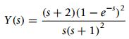
The transfer function of a LTI system is(a) Use the Laplace transform to find the unit-step response s(t) = (h ˆ— x) (t).(b) Find the response due to the following inputs(i) x1(t) = u(t) ˆ’ u(t ˆ’ 1), (ii) x2(t) = δ(t) ˆ’ δ(t
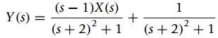
You are given the following Laplace transform of the output y(t)of a system with input x(t)and Laplace transform X(s):(a) If x(t) = u(t), find the zero-state response yzs(t).(b) Find the zero-input response yzi(t).(c) Determine the steady-state solution yss(t). (s – 1)X(s) Y (s) = (s +
A system is represented by the following ordinary differential equationwhere y(t)is the system output and x(t)is the input.(a) Find the transfer function H(s) = Y(s)/X(s)of the system. From its poles and zeros determine if the system is BIBO stable or not.(b) If x(t) = u(t), and initial
In the following problems we use the inverse Laplace transform and the relation between input and output of LTI systems.(a) The Laplace transform of the output of a system isfind y1(t), assume it is causal.(b) The Laplace transform of the output y2(t)of a second-order system isIf the input of
To find the Laplace transform of x(t)=r(t)−2r(t−1)+2r(t−3)−r(t−4).(a) Plot x(t). Calculate dx(t)/dt, d2x(t)/dt2 and plot them.(b) Use the Laplace transform of d2x(t)/dt2 to obtain X(s).
Find the Laplace transform of the following signals and their region of convergence:(a) the reflection of the unit-step signal, i.e., u(−t). And then use the result together with the Laplace transform of u(t)to see if you can obtain the Laplace transform of a constant or x(t) = u(t) +
Consider the pulse x(t) = u(t) ˆ’ u(t ˆ’ 1). Find the zeros and poles of X(s)and plot them.(a) Suppose x(t)is the input of a LTI system with a transfer function H(s) = Y(s)/X(s) = 1/(s2 + 4Ï€2), find and plot the poles and zeros of Y(s) = L[y(t)]), where y(t)is
In the following problems properties of the Laplace transform are used.(a) Show that the Laplace transform of x(t) eˆ’at u(t)is X(s + a), where X(s) = L[x(t)] and then use it to find the Laplace transform of y(t) = cos(t) eˆ’2tu(t).(b) A signal x1(t) has as Laplace
Find the Laplace transform of the following signals and in each case determine the corresponding region of convergence:(a) the signal x(t) = eˆ’αtu(t) ˆ’ eαt u( ˆ’ t) when (i) α > 0, (ii) α †’
Consider the following cases involving sinusoids:(a) Find the Laplace transform of y(t) = sin(2π t)[u(t) − u(t − 1)]and its region of convergence. Carefully plot y(t). Determine the region of convergence of Y(s).(b) A very smooth pulse, called the raised cosine, is x(t) = 1−cos(2π
Find the Laplace transform of the following(a) anti-causal signals indicating their region of convergence:(i) x(t) = etu(−t),
Find the Laplace transform of the following(a) finite support signals, and indicate their region of convergence:(i) x(t) = δ(t − 1), (ii) y(t) = δ(t + 1) − δ(t − 1)(iii) z(t) = u(t + 1) − u(t − 1), (iv) w(t) = cos(2π t) [u(t + 1) − u(t − 1)](b) causal signals, and
The impulse response of an ideal low-pass filter is h(t) = sin(t)/t.(a) Given that the impulse response is the response of the system to an input x(t) = δ(t) with zero initial conditions, can an ideal low-pass filter be used for real-time processing? Explain.(b) Is the ideal low-pass
The impulse response of a LTI is h(t) = e−2tu(t). Use MATLAB functions to approximate the convolution integral when the inputs of the system arex1(t) = cos(2π t) [u(t) − u(t − 20)], x2(t) = sin(π t)e−20t[u(t) − u(t − 20)]x3 (t) = r(t) − 2r(t − 2) + r(t − 4)Plot the impulse
An analog averager is given by(a) Let x(t) = u(t) ˆ’ u(t ˆ’ 1) find the average signal y(t) using the above integral. Let T = 1. Carefully plot y(t). Verify your result by graphically computing the convolution of x(t) and the impulse response h(t) of the averager.(b) To see the
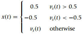
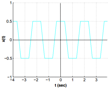
A zener diode is such that the output corresponding to an input vs(t) = cos(Ï€t)is a €œclipped€ sinusoidas shown in Figure 2.21 for a few periods. Use MATLAB to generate the input and output signals and plot them in the same plot for 0 ‰¤ t ‰¤
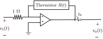
The following op-amp circuit is used to measure the changes of temperature in a system (Figure 2.20). The output voltage is given byvo(t) = ˆ’R(t)vi(t)Suppose that the temperature in the system changes cyclically after t = 0, so thatR(t) = [1 + 0.5 cos(20Ï€ t)]u(t).Let the input
The bounded-input bounded-output stability assumes that the input is always bounded, limited in amplitude. If that is not the case, even a stable system would provide an unbounded output. Consider the analog averager, with an input-output relationship(a) Suppose that the input to the averager is a
An echo system could be modeled using or not using feedback.(a) Feedback systems are of great interest in control and in modeling of many systems. An echo is created as the sum of one or more delayed and attenuated output signals that are fed back into the present signal. A possible model for
The impulse response h(t) of a causal, linear, time-invariant continuous-time system isAssuming zero initial conditions, determine the outputs yi(t), i = 1,2, of this system if the input is(a) x1(t) = u(t) ˆ’ u(t ˆ’ 2) (b) x2(t) = δ(t) ˆ’
A quadrature amplitude modulation (QAM) system is a communication system capable of transmitting two messages m1(t), m2(t) at the same time. The transmitted signal s(t) iss(t) = m1(t) cos(Ωct) + m2(t) sin(Ωct)Carefully draw a block diagram for the QAM system.(a) Determine if the system is
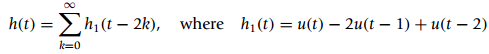
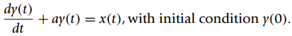
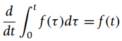
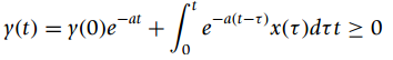
Consider a system represented by a first-order ordinary differential equation:(a) Show first that for a function f(t)using the definition of the derivative.(b) Apply the above result to show that the solution of the first-order ordinary differential equation with initial condition y(0) given
The input x(t) and the corresponding output y(t) of a linear time-invariant (LTI) system arex(t) = u(t) − u(t − 1) → y(t) = r(t) − 2r(t − 1) + r(t − 2)Determine the outputs yi(t), i = 1, 2, 3 corresponding to the following inputs(a) x1(t) = u(t) − u(t − 1) − u(t − 2) + u(t −
The input-output equation characterizing a system of input x(t) and output y(t) isand zero otherwise.(a) Find the ordinary differential equation that also characterizes this system.(b) Suppose x(t) = u(t) and any value of y(0), we wish to determine the steady state response of the system. Is the
The response of a first-order system is for t ‰¥ 0and zero otherwise.(a) Consider y(0) = 0 is the system linear? If y(0) ‰ 0, is the system linear? Explain.(b) If x(t) = 0, what is the response of the system called? If y(0) = 0 what is the response of the system to any input
Consider the system where for an input x(t) the output is y(t) = x(t)f(t).(a) Let f(t) = u(t) − u(t − 10), determine whether the system with input x(t) and output y(t) is linear, time-invariant, causal, and BIBO stable.(b) Suppose x(t) = 4cos(π t/2), and f(t) = cos(6π t/7) and both are
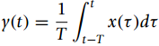
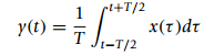
Consider the analog averager,where x(t) is the input and y(t) the output.(a) Find the impulse response h(t) of the averager. Is this system causal?(a) Let x(t) = u(t), find the output of the averager. rl+172 x(t)dt y(t) = 1-T/2
An analog system has the following input-output relation,and zero otherwise. The input is x(t) and y(t) is the output.(a) Is this system LTI? If so, can you determine without any computation the impulse response of the system? Explain.(b) Is this system causal? Explain.(c) Find the
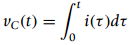
A time-varying capacitor is characterized by the charge-voltage equation q(t) = C(t) v(t). That is, the capacitance is not a constant but a function of time.(a) Given that i(t) = dq(t)/dt, find the voltage-current relation for this time-varying capacitor.(b) Let C(t) = 1 + cos(2π t) and
An RC circuit in series with a voltage source x(t) is represented by a ordinary differential equationwhere y(t) is the voltage across the capacitor. Assume y(0) is the initial voltage across the capacitor.(a) If it is known that the resistor has a resistance R, and the capacitor C = 1 F. Draw
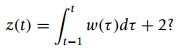
(a) A system is represented by the ordinary differential equation dz(t)/dt = w(t) ˆ’ w(t ˆ’ 1) where w(t) is the input and z(t) the output.i. How is this system related to an averager having an input/output equationii. Is the system represented by the given ordinary differential
The input-output relationship of a system iswhere x(t) is the input and y(t) the output.(a) Let the input be x(t) = sin(2Ï€t) u(t), plot the corresponding output y(t). What is the output of the system if we double the input? That is, what is the output y1(t) if the input x1(t) =
Consider an averager represented by the input/output equationwhere x(t) is the input and y(t) the output.(a) Let the input be x1(t) = δ(t), find graphically the corresponding output y1(t) for ˆ’ˆž < t < ˆž. Let then the input be x2(t) = 2x1(t), find
Showing 400 - 500
of 522
1
2
3
4
5
6
Step by Step Answers