New Semester
Started
Get
50% OFF
Study Help!
--h --m --s
Claim Now
Question Answers
Textbooks
Find textbooks, questions and answers
Oops, something went wrong!
Change your search query and then try again
S
Books
FREE
Study Help
Expert Questions
Accounting
General Management
Mathematics
Finance
Organizational Behaviour
Law
Physics
Operating System
Management Leadership
Sociology
Programming
Marketing
Database
Computer Network
Economics
Textbooks Solutions
Accounting
Managerial Accounting
Management Leadership
Cost Accounting
Statistics
Business Law
Corporate Finance
Finance
Economics
Auditing
Tutors
Online Tutors
Find a Tutor
Hire a Tutor
Become a Tutor
AI Tutor
AI Study Planner
NEW
Sell Books
Search
Search
Sign In
Register
study help
computer science
signals and systems
Signals and Systems using MATLAB 2nd edition Luis Chaparro - Solutions
The following problems relate to the response of LTI discrete-time systems.(a) The unit-step response of a LTI discrete-time system is found to be s[n] = (3 − 3(0.5)n+1 )u[n]. Use s[n] to find the impulse response h[n] of the system.(b) The output y[n] of a discrete-time system is the
An LTI discrete-time system has an impulse response h[n] = u[n] − u[n − 4], and as input the signal x[n] = u[n] − u[n − (N + 1)] for a positive integer N. The output of the system y[n] is calculated using the convolution sum.(a) If N = 4 what is the length of the output y[n]?
Consider a discrete-time system represented by the difference equa-tion y[n] = 0.5y[n ˆ’ 1] + x[n] where x[n] is the input and y[n] the output.(a) An equivalent representation of the system is given by the difference equationy[n] = 0.25y[n ˆ’ 2] + 0.5x[n ˆ’ 1] +
An LTI discrete time system has the impulse response h[n] = (−1)n u[n]. Use the convolution sum to compute the output response y[n],n ≥ 0, when the input is x[n] = u[n] − u[n − 3] and the initial conditions are zero. In particular, find the following values of the out-put y[n],0 ≤ n ≤ 4.
An LTI causal discrete-time system has the input/output relationshipwhere x[n] is the input of the system, y[n] is the response of the system.There is zero initial energy in the system prior to applying x[n].(a) Find the impulse response h[n].(b) Find the unit-step response of the given
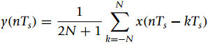
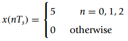
A discrete-time averager is characterized by the following equation relating the input x(nTs) with the output y(nTs)(a) Is this system causal? Explain.(b) Let N = 2 in the above equation. Find and plot the impulse response h(nTs) of the averager.(c) For N = 2, if the input to the
Consider a causal LTI system with impulse response h[n], and input x[n] = x1[n] ˆ’ x1[n ˆ’ 2] + x1[n ˆ’ 4] where x1[n] = u[n]ˆ’ u[n ˆ’ 2]. The impulse response of the system is h[n] = u[n] ˆ’ u[n ˆ’ 2](a) Use the convolution
An LTI system represented by the difference equation y[n] = ˆ’ y[n ˆ’ 1] + x[n], n ‰¥ 0, is initially at rest. The input of the system is x[n] and the output y[n].(a) Using the difference equation find the system response y[n] for n ‰¥ 0 when the input
The output of a discrete-time system is y[n] = w[n] x[n] where x[n] is the input, and w[n] = u[n] − u[n − 5] is a rectangular window.(a) The input is x[n] = 4 sin (πn/2), −∞ < n < ∞, determine if x[n] is periodic, and if so indicate its fundamental period N0.(b) Let z[n]
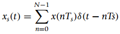
A finite impulse response (FIR) filter has an input/output relation y[n] = x[n] − x[n − 5] where x[n] is the input and y[n] the output.(a) Find the impulse response h[n] of this filter. Plot h[n] as a function of n, and indicate if the filter is causal and BIBO stable or
Consider the following problems related to properties of filters.(a) Filters that operate under real-time conditions need to be causal, i.e., they can only process present and past inputs. When no real-time processing is needed the filter can be non-causal.i. Consider the case of averaging an
Consider the formulax[n] = x[n − 1] + x[n − 3] n ≥ 3x[0] = 0x[1] = 1x[2] = 2Find the rest of the sequence for 0 ≤ n ≤ 50 and plot it using function stem.
Given the discrete signal x[n] = 0.5nu[n].(a) Use the function stem to plot the signal x[n] for n = ˆ’5 to 20.(b) Is this a finite-energy discrete-time signal? i.e., compute the infinite sum(c) Verify your results by using symbolic MATLAB to find an expression for the above sum.
Consider an analog periodic sinusoid x(t) = cos (3πt + π/4) being sampled using a sampling period Ts to obtain the discrete-time signal x[n] = x(t)|t=nTs = cos(3πTs n + π/4).(a) Determine the discrete frequency of x[n](b) For what values of Ts is the discrete-time signal x[n]
Suppose you sample the analog signalwith a sampling period Ts = 0.25 to generate x[n] = x(t)|t=nTs.(a) Use the function stem to plot x[n] and x[ˆ’n] for an appropriate interval.(b) Find the even, xe[n], and the odd, xo[n], components of x[n]. Plot them using stem. Verify that
Periodic signals can be generated by obtaining a period and adding shifted versions of this period. Suppose we wish to generate a train of triangular pulses. A period of the signal is x[n] = 0.5(r[n] ˆ’ 2r[n ˆ’ 2] + r[n ˆ’ 4]) where r[n] is the discrete-time ramp
Consider the discrete-time signal x[n] = cos (2πn/7).(a) The discrete-time signal can be compressed by getting rid of some of its samples (down-sampling). Consider the down-sampling by 2. Write a script to obtain and plot z[n] = x[2n]. Plot also x[n] and compare it with z[n], what happened?
In the generation of music by computer, the process of modulation is extremely important. When playing an instrument, the player typically does it in three stages: (1) rise time, (2) sus-tained time and (3) decay time. Suppose we model these three stages as an envelope continuous-time signal given
An A/D converter can be thought of composed of three subsystems: a sampler, a quantizer, and a coder.(a) The sampler, as a system, has as input an analog signal x(t) and as output a discrete-time signal x(nTs) = x(t)|t=nTs, where Ts is the sampling period. Determine whether the sampler is a
A window is a signal w[n] that is used to highlight part of another signal. The windowing process consists in multiplying an input signal x[n] by the window signal w[n], so that the output is y[n] = x[n] w[n]. There are different types of windows used in signal processing; one of them is the
A discrete-time IIR system is represented by the following difference equation y[n] = 0.15y[n−2]+x[n], n ≥ 0 where x[n] is the input and y[n] is the output.(a) To find the impulse response h[n] of the system, let x[n] = δ[n], y[n] = h[n], and the initial conditions be zero. Find
An FIR filter has a non-recursive input/output relation(a) Find the impulse response h[n] of this filter.Is this a causal and stable filter?Explain(b) Find the unit-step response s[n] for this filter and plot it.(c) If the input x[n] for this filter is bounded,
The impulse response of a discrete-time system is h[n] = ( − 0.5)n u[n].(a) If the input of the system is x[n] = δ[n] + δ[n − 1] + δ[n − 2], use the linearity and time-invariance of the system to find the corresponding output y[n].(b) Find the convolution sum corresponding to the
Suppose an IIR system is represented by a difference equation y[n] = a y[n − 1] + x[n], where x[n] is the input and y[n] is the output.(a) If the input is x[n] = u[n] and it is known that the steady-state response is y[n] = 2, what would be a for that to be possible (in steady state x[n] = 1
The unit-step response of a discrete-time LTI system iss[n] = 2[( − 0.5)n − 1] u[n]Use this information to find(a) The impulse response h[n] of the discrete-time LTI system.(b) The response of the LTI system to a ramp signal x[n] = nu[n].
The poles of the Laplace transform X(s) of an analog signal x(t) are p1,2 =−1 ± j1, p3 = 0, p4,5 = ±j1, and there are no zeros. If we use the transformation z = esTs with Ts = 1,(a) Determine where the given poles are mapped into the z-plane. Carefully plot the poles and zeros of the
The sign functionextracts the sign of a real valued signal, i.e.,(a) Let s[n] = s1[n] + s2[n], x[n] = n, where s1[n] is causal and s2[n] anti-causal; find their Z-transforms and indicate the corresponding ROCs.(b) Determine the Z-transform S(z). -1 x[n] < 0 s[n] = sign(x[n]) =
Given the anti-causal signal x[n]= −αn u[−n](a) Determine its Z-transform X(z), and carefully plot the ROC when α = 0.5 and α = 2. For which of the two values of α does X(ejω) exist?(b) Find the signal that corresponds to the derivative dX(z)/dz. Express it in terms of α.
An analog pulse x(t) = u(t) ˆ’ u(t ˆ’ 1) is sampled using a sampling period Ts= 0.1.(a) Obtain the discrete-time signal x(nTs) = x(t)|t=nTs and plot it as a function of nTs(b) If the sampled signal is represented as an analog signal asdetermine the value of N in the
Consider the signal x[n] = 0.5(1+ [−1]n) u[n](a) Plot x[n]and use the sum definition of the Z-transform to obtain its Z-transform, X(z).(b) Use the linearity property and the Z-transforms of u[n]and [−1]n u[n] to find the Z-transform X(z) = Z[x[n]]. Compare this result with the
A LTI system is represented by the first-order difference equationy[n] = x[n] − 0.5y[n − 1] n ≥ 0where y[n] is the output and x[n] is the input.(a) Find the Z-transform Y(z) in terms of X(z) and the initial condition
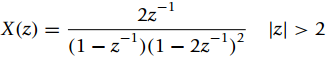
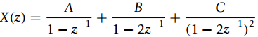
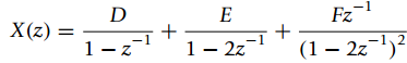
When finding the inverse Z-transform of a function with zˆ’1terms in the numerator, zˆ’1can be thought of a delay operator to simplify the calculation. For(a) Use the Z-transform of u[n] and the properties of the Z-transform to find x[n].(b) Use your result for x[n]
A second-order system is represented by the difference equation y[n] = 0.25y[n − 2] + x[n] where x[n] is the input and y[n] the output.(a) For the zero-input case, i.e., when x[n] = 0, find the initial conditions y[ − 1] and y[ − 2] so that y[n] = 0.5n u[n].(b) Suppose the input is
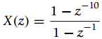
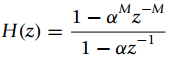
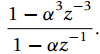
Consider the following problems related to LTI systems.(a) The impulse response of an FIR filter is h[n]= αn(u[n] ˆ’ u[n ˆ’ M])i. Is it true that the transfer function for the filter isfor any value of α?ii. Let M = 3, 0 ‰¤
The transfer function of a causal LTI discrete-time system is H(z) = (1 + z−1)/(1 − .5z−1).(a) Find the poles and zeros of H(z). Choose the correct region of con-vergence corresponding to H(z)from the following and explain why(i) |z| < 0.5, (ii) 0.5
Suppose we cascade a differentiator and a smoother. The equations for the differentiator is w[n] = x[n] ˆ’ x[n ˆ’ 1] where w[n] is the output and x[n] the input, and for the smoother the equation iswhere y[n] is the output and w[n] the input.(a) Obtain the difference
An LTI discrete-time system is characterized by the difference equationy[n] + ay[n − 1] + by[n − 2] = x[n]Determine for which of the the following sets of coefficients the system is BIBO stable(i) a = 2, b = 2, (ii) a = 1, b = 0.5.
Consider a discrete-time LTI system represented by the difference equation with the given initial conditiony[n] + 0.5y[n − 1] = 2(x[n] − x[n − 1]) n ≥ 0, y[ − 1] = 2where x[n] is the input and y[n] the output.Suppose the input of the system is x[n]
Determine the impulse response h[n]of the feedback system shown in Figure 10.18. Determine if the system is BIBO stable.Figure 10.18: e[n] r[n]- Delay y[n]
Consider the following problems for LTI discrete-time systems.(a) The input and the output of a LTI discrete-time system areFind the transfer function H(z).(b) The transfer function of an LTI discrete-time system isi. Is this system causal? Explain.ii. Determine the impulse response of
The following problems relate to FIR and IIR systems.(a) The input and the output of a causal LTI discrete-time system areDetermine the impulse response h[n].(b) The transfer function H(z)of an LTI discrete-time system has a pole at z = 0, a double zero at z = ˆ’1 and a dc gain
The Z-transform of the unit-step response of a causal LTI discrete-time system isDetermine the impulse response of the system. 1.5 S(z) = 1 1– 0.5z- -1
The impulse response of a causal LTI discrete-time system is(a) If the input of the system is a pulse x[n] = u[n] ˆ’ u[n ˆ’ 3], determine the length of the output of the system y[n]. Graphically calculate the output of the system y[n] as the convolution sum of x[n]
The transfer function of an RLC circuit is H(s) = Y(s)/X(s) = 2s/(s2 +2s+1).(a) Obtain the ordinary differential equation with input x(t) and output y(t). Approximating the derivatives by differences (let T=1) obtain the difference equation that approximates the differential
We are given a noisy signalx(t) = s(t) + η(t)where s(t) is the desired signal and η(t) is additive noise. From experience, we know that the average power of the desired signal and the noise has finite support. That is|S(f)|2 = 0 f ‰¥ 10 kHz|N(f)|2 = 0
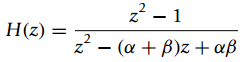
The transfer function of a discrete-time system iswith α = r1 ejθ1 and β = r2ejθ2, where ri > 0 and θi are angles between 0 and 2π(a) Determine the range of values of r1 and r2 for which the impulse response h[n] of
Suppose we cascade a €œdifferentiator€ and a €œsmoother€ systems characterized by the following input/output equationswhere the output of the differentiator and input to the smoother is w[n], while x[n] is the input of the differentiator (and of the overall
A model for echo generation is shown in Figure 10.20.(a) Calculate the transfer function H(z) = Y(z)/X(z) of the echo sys-tem shown above.(b) Suppose you would like to recover the original signal x[n] from the output signal y[n] by passing it through a LTI system with transfer
Suppose we are given a finite-length sequence h[n](it could be part of an infinite-length impulse response from a discrete system that has been windowed) and would like to obtain a rational approximation for it. This means that if H(z) = Z[h[n]], a rational approximation of it
The following are matrices for the state variable and the output equations of a LTI systemAssume vi[n], i = 1, 2, are the state variables, and x[n] the input and y[n] the output. Use the following transformation matrixto obtain a different set of state variablesw[n] = Tv[n].Obtain the
Given the matrices corresponding to the state and output equations for a system with input x[n] and output y[n]:(a) Find the transfer function H(z) = Y(z)/X(z) corresponding to the state and output equations.(b) Obtain a minimum realization for H(z). Draw a block diagram of the
Consider the following two state-variable representationswhere the first is the controller form and the second the observer form. Find the corresponding functions Hc(z) = Yc(z)/Xc(z) and Ho(z) = Yo(z)/Xo(z), for inputs xc[n], xo[n] and outputs yc [n] and yo[n]. How are Hc(z) and Ho (z)
Find an invertable transformation represented by the matrixthat changes the controller form into the observer form given in the previous problem. t2 t1 т t4 t3 ||
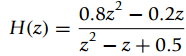
Find a state variable and output matrix equations corresponding to the transfer function 0.8z – 0.2z z - z+ 0.5 Н(2). ||
Consider the Fibonacci sequence generated by the difference equation f[n] = f[n − 1] + f[n − 2], n ≥ 0 with initial conditions f[ − 1] = 1, f[ − 2] = −1.(a) Find the Z-transform of f[n], or F(z). Find the poles φ1, and φ2 and the zeros of F(z). How are the poles connected?
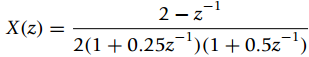
Use symbolic MATLAB to find the inverse Z-transform ofand determine x[n] as n †’ ˆž. 2 – z -1 X (z) 2(1+0.25z-)(1+0.5z¬)
Consider a second-order discrete-time system represented by the following difference equation:y[n] − 2r cos(ω0) y[n − 1] + r2y[n − 2] = x[n] n ≥ 0where r > 0 and 0 ≤ ω0 ≤ 2π, y[n] is the output and x[n]the input.(a) Find the transfer
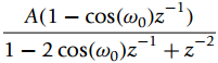
Given that the Z-transform of a discrete-time cosine A cos(ω0n) u[n] is(a) Use the given Z-transform to find a difference equation whose output y[n] is a discrete-time cosine A cos(ω0 n) and input x[n] = δ[n]. What should you use as initial
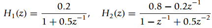
Two systems with transfer functionsare connected in parallel.(a) Use MATLAB to determine the transfer function H(z)of the over-all system.(b) Use the function tf2ssto obtain state-variable representations for H1 (z) and H2 (z), and the use ss2tfto verify these transfer functions are the
We are interested in the unit-step solu-tion of a system represented by the following difference equation y[n] = y[n − 1] − 0.5y[n − 2] + x[n] + x[n − 1](a) Find an expression for Y(z).(b) Do a partial expansion of Y(z).(c) Find the inverse Z-transform y[n]. Use MATLAB to verify
The Pade approximant provides an exact matching of M + N – 1 values of h[n], where M and N are the orders of the numerator and denominator of the rational approximation. But there is no method for choosing the numerator and denominator orders, M and N. Also, there is no guarantee on how
Consider finding the inverse Z-transform of(a) MATLAB does the partial fraction expansion as:while we do it in the following form:Show that the two partial fraction expansions give the same result.(b) Obtain x[n]analytically using the two expansions and verify your answer with
Suppose that a state realization has the following matricesFind the corresponding transfer function and verify it using the function ss2tf. Obtain a minimal realization of this system. Draw a block diagram of the realization. =[1o] [0 1] = >' -2 1 ,bo A, -1 0 -1
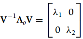
Suppose you are given the observer space representation with matrix and vectorsTo find a transformation that diagonalizes Ao use MATLAB function eigswhich calculates the eigenvalues and eigenvectors corresponding to the matrix and allows us to expresswhere V is a matrix created with the
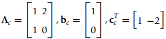
For the system in Part 1, consider the state variablesv1(t) = y(t) v2(t)=ẏ(t) + y(t) − x(t)(a) Obtain the matrix A2 and the vectors b2 and cT2 for the state and the output equations that realize the ordinary differential equation in Part 1.(b) Draw a block diagram for the state
A LTI system is represented by an ordinary differential equation(a) Obtain the transfer function H(s) = Y(s)/X(s) = B(s)/A(s) and find its poles and zeros. Is this system BIBO stable? Is there any pole-zero cancelation?(b) Decompose H(s) as W(s)/X(s) = 1/A(s) and Y(s)/W(s) = B(s) for an
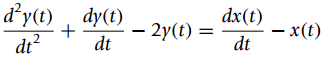
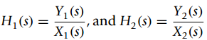
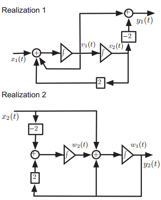
Given the two realizations in Figure 6.27 obtain the corresponding transfer functionsFigure 6.27: Y1 (s) Н () %— X1 (s) Y,(s) -, and H2(s) X,(s) Realization 1 y1 (t) v1(t) v2(t) r1(t) Realization 2 x2(t) w2(t) wi(t) 42(t) 2) 2.
You are given a state-variable realization of a second-order system hav-ing the following matrix and vectors(a) Find an invertible matrix F that can be used to transform the given state and output equations into state and output equations with matrix and vectors:(b) Assume thatis there an
Let the transfer function of a system beShow that by defining the state-variables asv1(t) = y(t),v2(t)=Ë™ y(t) + a1y(t) ˆ’ b1x(t)we obtain a minimal state variable and output realization (i.e., only two integrators are needed). Show the matrices/vectors for the state and the
To explore the performance of a proportional-plus-derivative controller on a second-order system, let Gp(s) = 1/(s(s + 1)) be the transfer function of the plant and Gc(s) = K1 + K2s be the controller.(a) Find the transfer function H(s) = Y(s)/X(s) of a negative feedback system with Gc(s) and
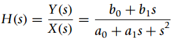
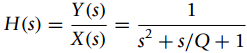
Consider a second-order system with transfer functionwhere Y(s) and X(s) are the Laplace transforms of output y(t) and the input x(t) of the system. Q is called the quality factor.(a) If the feedback gain is unity, determine the feedforward transfer function G(s).(b) Find the poles of
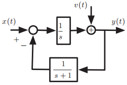
The feedback system shown in Figure 6.26 has two inputs: the conventional input x(t) = eˆ’tu(t) and a disturbance input v(t) = (1ˆ’eˆ’t) u(t).(a) Find the transfer functions Y(s)/X(s) and Y(s)/V(s).(b) Determine the output y(t).Figure 6.26: v(t) a(t) y(t) s +1
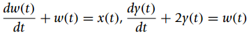
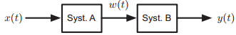
Consider the cascade connection of two continuous-time systems shown in Figure 6.25where(a) Determine the input/output differential equation for the overall cascade connection.(b) Suppose that w(0) = 1, y(0) = 0 and x(t) = 0 for t ‰¥0,i. Compute w(t) for t ‰¥ 0.ii. Compute then
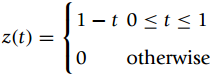
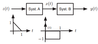
Consider the cascade of two continuous-time systems shown in Figure 6.24. The input-output characterization of system A is x(t) = dz(t)/dt. It is known that system B is linear and time-invariant, and that when x(t) = δ(t) its output is y(t)=eˆ’2tu(t), and that when the input
Consider the following problems connected with the feedback system shown in Figure 6.23.(a) The transfer function of the plant in Figure 6.23 is G(s) = 1/(s(s + 1)). If we want the impulse response of the feedback system to beh(t) = 0.5774eˆ’t sin(ˆš3t) u(t)find the value
Let H(s) = Y(s)/X(s) be the transfer function of the feedback system in Figure 6.22. The impulse response of the plant (with transfer function Hp(s)) is hp(t) = sin(t) u(t).(a) If we want the impulse response of the feedback system (with input x(t) and output y(t)) to be h(t) =
The feed forward transfer function of a negative feedback system is G(s) = N(s)/D(s), and the feedback transfer function is unity. Let X(s) be the Laplace transform of the input x(t) of the feedback system.(a) Given that the Laplace transform of the error is E(s) = X(s)[1 − F(s)] where F(s)
A resistor R = 1Ω, a capacitor C = 1 F and an inductor L = 1 H are connected in series with a source vi(t). Consider the output the voltage across the capacitor vo(t).(a) Use integrators and adders to implement the differential equation that relates the input vi(t) and the output vo(t) of
Consider a series RC circuit with input a voltage source vi(t) and output the voltage across the capacitor vo(t).(a) Draw a negative feedback system for the circuit using an integrator, a constant multiplier, and an adder.(b) Let the input be a battery, i.e., vi(t) = Au(t), find the
The transfer function H(s) = 1/(s + 1)2of a filter is to be implemented by cascading two first order filters Hi(s) = 1/(s + 1), i = 1, 2.(a) Implement Hi(s) as a series RC circuit with input vi(t) and output vi +1(t), i = 1, 2. Cascade two of these circuits and find the overall transfer function
Consider the following filters with the given poles and zeros, and dc constantH1(s): K = 1 poles p1 = −1, p2,3 = −1 ± jπzeros z1 = 1,z2,3 = 1 ± jπH2(s): K = 1 poles p1 = −1, p2,3 = −1 ± jπzeros z1,3 = ± jπH3(s): K = 1 poles p1 = −1, p2,3 = −1 ± jπzero z1 = 1Use MATLAB to plot
Consider an RLC series circuit with a voltage source vs(t). Let the values of the resistor, capacitor, and inductor be unity. Plot the poles and zeros and the corresponding frequency responses of the filters with output the voltage across the• Capacitor• Inductor• Resistor.Indicate the type
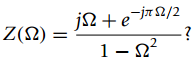
Consider the signal x(t) = u(t + 1) ˆ’ 2u(t) + u(t ˆ’ 1) and let(a) Plot x(t) and y(t)(b) Find X(Ω) and carefully plot its magnitude spectrum. Is X(Ω) real? Explain. (Use MATLAB to do the plotting.)(c) Find Y(Ω) and carefully plot its
The smoothness of the signal determines the frequency content of its spectrum. Consider the signalsx(t) = u(t + 0.5) − u(t − 0.5),y(t) = (1 + cos(π t))[u(t + 0.5) − u(t − 0.5)](a) Plot these signals. Can you tell which one is smoother?(b) Find X(Ω) and carefully plot its magnitude
The supports in time and in frequency of a signal x(t) and its Fourier transform X(Ω)are inversely proportional. Consider a pulse(a) Let T0 = 1, and T0 = 10 and find and compare the corresponding |X(Ω)|.(b) Use MATLAB to simulate the changes in the magnitude spectrum when T0
The connection between the Fourier series and the Fourier transform can be seen by considering what happens when the fundamental period of a periodic signal increases to a point at which the periodicity is not clear as only one period is seen. Consider a train of pulses x(t) with fundamental period
A pure tone x(t) = 4 cos(1000t) is transmitted using an amplitude mod-ulation communication system with a carrier cos(10000t). The output of the AM system isy(t) = x(t) cos(10000t)At the receiver, the sent signal y(t) needs first to be separated from the thousands of other signals that are
Suppose you want to design a dc-source using a half-wave rectified signal x(t) and an ideal filter. Let x(t) be periodic, T0= 2, and with a period(a) Find the Fourier transform X(Ω) of x(t), and plot the magnitude spectrum including the dc and the first three harmonics.(b) Determine the
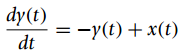
An analog averager is characterized by the following relationshipwhere x(t) is the input and y(t) the output. If x(t) = u(t) ˆ’ 2u(t ˆ’ 1) + u(t ˆ’ 2),(a) find the Fourier transform of the output Y(Ω);(b) find y(t) from Y(Ω). dy(t) dt —D
The sampling signalwill be important in the sampling theory later on.(a) As a periodic signal of fundamental period Ts€™ express δTs(t) by its Fourier series.(b) Determine then the Fourier transform ˆ†(Ω) = F[δTs(t)].(c) Plot
As indicated by the derivative property, if we multiply a Fourier transform by (jΩ)N it corresponds to computing an Nth derivative of its time signal. Consider the dual of this property. That is, if we compute the derivative of X(Ω) what would happen to the signal in the time domain?(a) Let x(t)
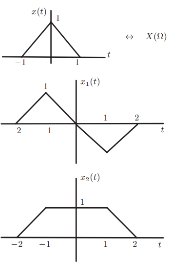
If the Fourier transform of the pulse x(t) given in Figure 5.14 is X(Ω) (do not need to compute it)(a) Using the properties of the Fourier transform (no integration needed) obtain the Fourier transforms of the signals xi(t), i = 1, 2, shown in Figure 5.14 in terms of
A continuous-time LTI system is represented by the ordinary differential equationwhere x(t) is the input and y(t) the output.(a) Determine the frequency response H(jΩ) of this system by considering the steady-state output of the system to inputs of the form x(t)=ejΩt, for
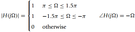
The Fourier series coefficients of a periodic signal x(t), with fundamental frequency Ω0= Ï€/4 are X1= Xˆ—ˆ’1=j, X5= Xˆ—ˆ’5= 2 and the rest are zero. Suppose x(t) is the input to a band-pass filter with the following magnitude and phase
Consider the cascade of two filters with frequency responsesH1(jΩ) = jΩ, and H2(jΩ) = 1e−jΩ(a) Indicate what each of the filters does.(b) Suppose that the input to the cascade isx(t) = p(t) cos(πt/2), where p(t) = u(t + 1) − u(t − 1)and the output is y(t). Find
The transfer function of a filter is(a) Find the poles and zeros of H(s) and use this information to sketch the magnitude response |H(jΩ)|of the filter. Indicate the magnitude response at frequencies 0, 1, and ˆž. Indicate what type of filter it is.(b) Find the
The Fourier transform of a signal x(t) is(a) Carefully plot X(Ω)as function of .(b) Determine the value of x(0). [u(2 +T) – u(S2 – 1)] X(2)
The frequency response of an ideal low-pass filter is(a) Calculate the impulse response h(t) of the ideal low-pass filter.(b) If the input of the filter is a periodic signal x(t) having a Fourier seriesdetermine the steady-state response yss(t) of the system. -2
Consider the raised cosine pulsex(t) = [1 + cos(π t)] (u(t + 1) − u(t − 1))(a) Carefully plot x(t).(b) Find the Fourier transform of the pulsep(t) = u(t + 1) − u(t − 1)(c) Use the definition of the pulse p(t) and the modulation property to find the Fourier transform of x(t) in
The following problems relate to the modulation property of the Fourier transform:(a) Consider the signalx(t) = p(t) + p(t) cos(Ï€ t) where p(t) = u(t + 1) ˆ’ u(t ˆ’ 1)i. Use the modulation property to find the Fourier transform X(Ω)in terms of
Showing 300 - 400
of 522
1
2
3
4
5
6
Step by Step Answers
![ο0 γίn]Σο.5)' x[n -k k=0 'x[n – k] (0.5](https://dsd5zvtm8ll6.cloudfront.net/si.question.images/images/question_images/1545/6/4/2/4265c20a1ba5fad91545625014126.jpg)
![п I (п - k+ 2)x[k] УIn] %3D — k=-00](https://dsd5zvtm8ll6.cloudfront.net/si.question.images/images/question_images/1545/6/4/2/7835c20a31f1f15d1545625371164.jpg)
![n = 0, 3 hT[n] = %3D otherwise](https://dsd5zvtm8ll6.cloudfront.net/si.question.images/images/question_images/1545/6/4/3/0935c20a455019f01545625680717.jpg)
![0, 1, 2 п %3 x[n] otherwise](https://dsd5zvtm8ll6.cloudfront.net/si.question.images/images/question_images/1545/6/4/3/3105c20a52e051441545625898000.jpg)
![n = 0, 1, 2, 3, 4, 5 x[n] = otherwise](https://dsd5zvtm8ll6.cloudfront.net/si.question.images/images/question_images/1545/6/4/3/3105c20a52e20d791545625898155.jpg)
![N-1 N-1 x[n – k] Уx[п — k], (В) (A) y[n] = k=0 2 (B) y[n] = k=-N+1](https://dsd5zvtm8ll6.cloudfront.net/si.question.images/images/question_images/1545/6/4/4/2555c20a8df6bc801545626843580.jpg)
![Σ Κ |x[n] εχ n=-00 ||](https://dsd5zvtm8ll6.cloudfront.net/si.question.images/images/question_images/1545/6/4/4/9805c20abb45b5431545627568223.jpg)
![3D x(п— 5k] У x[n — 5k] y[n]: k=-00](https://dsd5zvtm8ll6.cloudfront.net/si.question.images/images/question_images/1545/6/4/6/2125c20b084375ad1545628800302.jpg)
![[r(t) – r(t – 3)]-Ir(t – 20) – r(t – 30)] e(t) = 3 10](https://dsd5zvtm8ll6.cloudfront.net/si.question.images/images/question_images/1545/6/4/7/0885c20b3f0056021545629676161.jpg)
![γίn]Σw[n-k γ[n] kx[n k=0 k]](https://dsd5zvtm8ll6.cloudfront.net/si.question.images/images/question_images/1545/6/4/7/6455c20b61df2b031545630233349.jpg)
![-1 x[n] < 0 s[n] = sign(x[n]) = {0 x[n] = 0 x[n] style=](https://dsd5zvtm8ll6.cloudfront.net/si.question.images/images/question_images/1545/6/6/7/2805c2102d00c44f1545649867640.jpg)
![e[n] r[n]- Delay y[n]](https://dsd5zvtm8ll6.cloudfront.net/si.question.images/images/question_images/1545/6/7/2/8845c2118b438aae1545655471408.jpg)
![n = 0, 3 n = 0, 1 Output y[n] n = 1, 2 Input x[n] = otherwise otherwise](https://dsd5zvtm8ll6.cloudfront.net/si.question.images/images/question_images/1545/6/7/3/0865c21197ed708f1545655673896.jpg)
![n < 0 Input x[n] = (-1)](https://dsd5zvtm8ll6.cloudfront.net/si.question.images/images/question_images/1545/6/7/3/3205c211a6891d391545655907772.jpg)
![п %3D 0, 1 п hin] 3D { 0.25 п%3D2 = 2 otherwise](https://dsd5zvtm8ll6.cloudfront.net/si.question.images/images/question_images/1545/8/1/7/3535c234d098cef01545799938707.jpg)
![|S(S)? |N()P f (KHz) 10 r[n] y/n] H(2) x(t) y(t) Sampler Ideal D/A f.](https://dsd5zvtm8ll6.cloudfront.net/si.question.images/images/question_images/1545/8/1/7/8815c234f19878d31545800466445.jpg)
![Differentiator w[n] = x[n] – x[n – 1] w[n] У[n — 1] Smoother y[n] = 3 3 3.](https://dsd5zvtm8ll6.cloudfront.net/si.question.images/images/question_images/1545/8/1/8/1915c23504f7063c1545800776546.jpg)
![y[n] x[n] 0.5 0.25 ২](https://dsd5zvtm8ll6.cloudfront.net/si.question.images/images/question_images/1545/8/1/8/2785c2350a6aaf911545800863868.jpg)
![d = [-} 1], d= A : b = 3 1/3 -1/3 1](https://dsd5zvtm8ll6.cloudfront.net/si.question.images/images/question_images/1545/8/1/8/6595c235223610211545801244167.jpg)
![г - (оь.] —ај -аз т 0 b2 b = A =](https://dsd5zvtm8ll6.cloudfront.net/si.question.images/images/question_images/1545/8/1/8/7635c23528b445541545801347393.jpg)
![—ај -аz т C = |b, b, b. A. b1 d = [1 0] -a, 1 A, b. b2 -аз 0](https://dsd5zvtm8ll6.cloudfront.net/si.question.images/images/question_images/1545/8/1/9/0425c2353a2954281545801627535.jpg)
![=[1o] [0 1] = style=](https://dsd5zvtm8ll6.cloudfront.net/si.question.images/images/question_images/1545/4/0/1/9725c1cf674c60e21545384550332.jpg)
![BI ,d = [1 ] -11 ,bo A, -1 2 0 || ||](https://dsd5zvtm8ll6.cloudfront.net/si.question.images/images/question_images/1545/4/0/1/8995c1cf62be89dd1545384477349.jpg)
![.& - [, ъ] -a1 -ao Ac bị bo I|](https://dsd5zvtm8ll6.cloudfront.net/si.question.images/images/question_images/1545/3/9/6/4765c1ce0fc9bbdd1545379054355.jpg)

![-[u(t) — и(t — Тo)] To x(t) = ||](https://dsd5zvtm8ll6.cloudfront.net/si.question.images/images/question_images/1545/3/8/3/8985c1cafda0e5791545366476222.jpg)
![dy(t) dt —D 0.5[x(t) — х(t — 2)]](https://dsd5zvtm8ll6.cloudfront.net/si.question.images/images/question_images/1545/3/2/8/2595c1bd683f34eb1545310839041.jpg)