New Semester
Started
Get
50% OFF
Study Help!
--h --m --s
Claim Now
Question Answers
Textbooks
Find textbooks, questions and answers
Oops, something went wrong!
Change your search query and then try again
S
Books
FREE
Study Help
Expert Questions
Accounting
General Management
Mathematics
Finance
Organizational Behaviour
Law
Physics
Operating System
Management Leadership
Sociology
Programming
Marketing
Database
Computer Network
Economics
Textbooks Solutions
Accounting
Managerial Accounting
Management Leadership
Cost Accounting
Statistics
Business Law
Corporate Finance
Finance
Economics
Auditing
Tutors
Online Tutors
Find a Tutor
Hire a Tutor
Become a Tutor
AI Tutor
AI Study Planner
NEW
Sell Books
Search
Search
Sign In
Register
study help
computer science
systems analysis design
Computers As Components Principles Of Embedded Computing System Design 4th Edition Marilyn Wolf - Solutions
Define these signal types in a timing diagram:a. changing;b. stable.
Have someone else deliberately introduce a bug into one of your programs, and then use the appropriate debugging tools to find and correct the bug.
Draw a timing diagram with the following signals (where [t1,t2] is the time interval starting at t1 and ending at t2):a. signal A is stable [0,10], changing [10,15], stable [15,30]b. signal B is 1 [0,5], falling [5,7], 0 [7,20], changing [20,30]c. signal C is changing [0,10], 0 [10,15], rising
Identify the different bus transaction types in your platform. Compute the bestcase bus bandwidth.
Draw a timing diagram for a read operation on a bus in which the read includes two wait states.
Construct a simple program to perform some memory accesses. Use a logic analyzer to study the bus activity. Determine what types of bus modes are used for the transfers.
Construct a simple program to access memory in widely separated places.Measure the memory system bandwidth and compare to the best-case bandwidth.
Draw a timing diagram for a write operation on a bus in which the write takes two wait states.
Draw a timing diagram for a write operation with no wait states.
When would you prefer to use busy-wait I/O over interrupt-driven I/O?
Draw UML diagrams for the read of one character from an 8251 UART. To read the character from the UART, the device needs to read from the data register and to set the serial port status register bit 1 to 0.a. Draw a sequence diagram that shows the foreground program, the driver, and the UART.b.
If you could only have one of vectors or priorities in your interrupt system, which would you rather have?
Draw a UML state diagram for software processing of a vectored interrupt.The vector handling is performed by software (a generic driver) that executes as the result of an interrupt. Assume that the vector handler can read the interrupting device’s vector by reading a standard location. Your state
Draw a UML sequence diagram for an interrupt-driven read of a device.The diagram should include the background program, the handler, and the device.
Why do most programs use interrupt-driven I/O over busy/wait?
Why do most computer systems use memory-mapped I/O?
Write a simple loop that lets you exercise the cache. By changing the number of statements in the loop body, you can vary the cache hit rate of the loop as it executes. If your microprocessor fetches instructions from off-chip memory, you should be able to observe changes in the speed of execution
Draw a timing diagram for a burst write operation that writes four locations.
Draw a UML state diagram for a burst read operation with wait states. One state diagram is for the bus master and the other is for the device being read.
Draw a UML sequence diagram for a burst read operation with wait states.
Draw timing diagrams fora. a device becoming bus masterb. the device returning control of the bus to the CPU
Draw a UML sequence diagram for a complete DMA transaction, including the DMA controller requesting the bus, the DMA transaction itself, and returning control of the bus to the CPU.
Draw a UML sequence diagram that shows a DMA bus transaction and concurrent processing on the CPU.
Draw a timing diagram that shows a complete DMA operation, including handing off the bus to the DMA controller, performing the DMA transfer, and returning bus control back to the CPU.
Draw UML state diagrams for a bus mastership transaction in which one side shows the CPU as the default bus master and the other shows the device that can request bus mastership.
Draw a UML sequence diagram for a bus mastership request, grant, and return.
Draw a UML sequence diagram showing a read operation across a bus bridge.
Draw a UML sequence diagram showing a write operation with wait states across a bus bridge.
Draw a UML sequence diagram for a read transaction that includes a DRAM refresh operation. The sequence diagram should include the CPU, the DRAM interface, and the DRAM internals to show the refresh itself.
Draw a UML sequence diagram for an SDRAM read operation. Show the activity of each of the SDRAM signals.
What is the role of a memory controller in a computing platform?
What hardware factors might be considered when choosing a computing platform?
What software factors might be considered when choosing a computing platform?
Write ARM assembly language code that handles a breakpoint. It should save the necessary registers, call a subroutine to communicate with the host, and upon return from the host, cause the breakpointed instruction to be properly executed.
Assume an A/D converter is supplying samples at 44.1 kHz.a. How much time is available per sample for CPU operations?b. If the interrupt handler executes 100 instructions obtaining the sample and passing it onto the application routine, how many instructions can be executed on a 20-MHz RISC
If an interrupt handler executes for too long and the next interrupt occurs before the last call to the handler has finished, what happens?
Consider a system in which an interrupt handler passes on samples to an FIR filter program that runs in the background.a. If the interrupt handler takes too long, how does the FIR filters output change?b. If the FIR filter code takes too long, how does its output change?
Assume that your microprocessor implements an ICE instruction that asserts a bus signal that causes a microprocessor in-circuit emulator to start. Also assume that the microprocessor allows all internal registers to be observed and controlled through a boundary scan chain. Draw a UML sequence
Why might an embedded computing system want to implement a DOScompatible file system?
Name two example embedded systems that implement a DOS-compatible file system.
You are given a memory system with an overhead O = 2 and a single-word transfer time of 1 (no wait states). You will use this memory system to perform a transfer of 1024 locations. Plot total number of clock cycles T as a function of burst size B for 1 < = B < = 8.
You are given a bus which supports single-word and burst transfers. A single transfer takes 1 clock cycle (no wait states). The overhead of the single-word transfer is 1 clock cycles (O = 1). The overhead of a burst is 3 clock cycles (OB = 3). Which performs a two-word transfer faster: a pair of
You are given a 2-byte wide bus that supports single-byte, dual-word (same clock cycle), and burst transfers of up to 8 bytes (4 byte pairs per burst). The overhead of each of these types of transfers is 1 clock cycle (O = OB = 1)and a data transfer takes 1 clock cycle per single or dual word (D =
Determine the design parameters for an audio system:a. Determine the total bytes per second required for an audio signal of 16 bits/sample per channel, two channels, sampled at 44.1 kHz.b. Given a clock period P = 20 MHz for a bus, determine the bus width required assuming that nonburst mode
You are designing a system a bus-based computer: the input device I1 sends its data to program P1; P1 sends its output to output device O1. Is there any way to overlap bus transfers and computations in this system?
Compare the source code and assembly code for a moderate-size program.(Most C compilers will provide an assembly language listing with the -S flag.) Can you trace the high-level language statements in the assembly code? Can you see any optimizations that can be done on the assembly code?
Write a C code for a state machine that implements a four-cycle handshake.
Write C code for an FIR filter. Measure the execution time of the filter, either using a simulator or by measuring the time on a running microprocessor. Vary the number of taps in the FIR filter and measure execution time as a function of the filter size.
Use the circular buffer functions to write a C function that accepts a new data value, puts it into the circular buffer, and then returns the average value of all the data values in the buffer.
Write C code for a producer/consumer program that takes one value from one input queue, another value from another input queue, and puts the sum of those two values into a separate queue.
Generate a trace for a program using software techniques. Use the trace to analyze the program’s cache behavior.
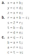
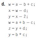
For each basic block given below, rewrite it in single-assignment form, and then draw the data flow graph for that form. a. x=a+b; y=c+d; z=x+e; b. r a+b c; - s=2*r; t-b-d; r d+e; C. a-q-r: b=a+t; a-r+s; c-t-u
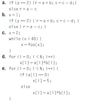
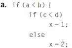
Draw the CDFG for the following code fragments: a. if (y 2) (r=a+b; s-c-d;} elser a C b. x 1; if (y-2) (r-a+b; s-c-d; } elser C. x=2; a c; } - while (x
Use a cycle-accurate CPU simulator to determine the execution time of a program.
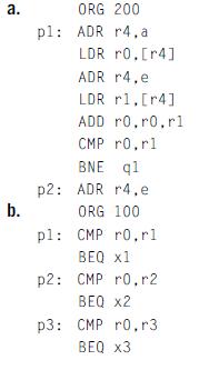
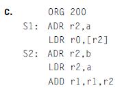
Show the contents of the assembler’s symbol table at the end of code generation for each line of the following programs: a. b. ORG 200 pl: ADR r4,a LDR r0.[r4] ADR r4.e LDR r1.[4] ADD ro.ro.rl CMP r0,rl BNE q1 p2: ADR r4.e ORG 100 pl: CMP ro.rl BEQ x1 p2: CMP r0.r2 BEQ x2 p3: CMP r0,r3 BEQ x3
Measure the power consumption of your microprocessor on a simple block of code.
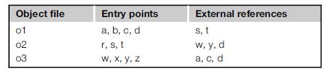
Your linker uses a single pass through the set of given object files to find and resolve external references. Each object file is processed in the order given, all external references are found, and then the previously loaded files are searched for labels that resolve those references. Will this
Use software testing techniques to determine how well your input sequences to the cycle-accurate simulator exercise your program.
Generate a set of functional tests for a moderate-size program. Evaluate your test coverage in one of two ways: have someone else independently identify bugs and see how many of those bugs your tests catch (and how many tests they catch that were not found by the human inspector); or inject bugs
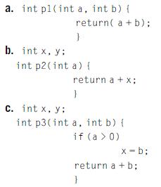
Determine whether each of these programs is reentrant. a. int pl(int a, int b) { b. int x, y: return( a + b); } int p2(int a) { C. int x, y: return a + x; } int p3(int a, int b) { if (a > 0) x-b; return a+b; }
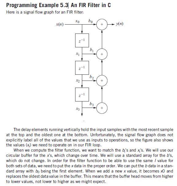
Is the code for the FIR filter of Programming Example 5.3 reentrant? Explain. Programming Example 5.3 An FIR Filter in C Here is a signal flow graph for an FIR filter: x(n) x0 bo y(n) b x1 b3 + The delay elements running vertically hold the input samples with the most recent sample at the top and
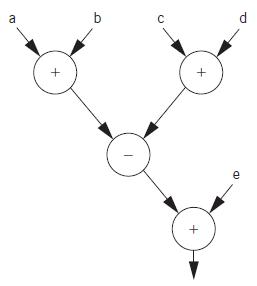
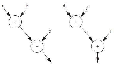
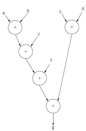
Provide the required order of execution of operations in these data flow graphs. If several operations can be performed in arbitrary order, show them as a set: {a + b, c - d}.a.b.c. C d + e
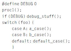
Draw the CDFG for the following C code before and after applying dead code elimination to the if statement: #define DEBUG 0 procl(); if (DEBUG) debug_stuff(); switch (foo) { case A: a case(); case B: b_case(); default: default_case(); }
Unroll the loop below:a. two timesb. three times for (i = 0; i < 32; i++) x[i] = a[i] * c[i];
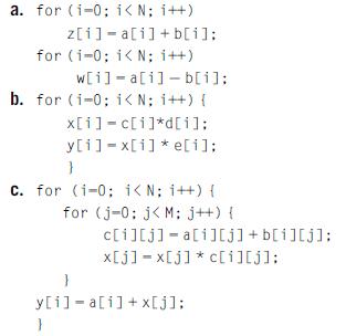
Apply loop fusion or loop distribution to these code fragments as appropriate.Identify the technique you use and write the modified code. a. for (i=0; i < N; i++) z[1] a[i]+b[i]; for (i=0; i < N; i++) w[i] a[i] b[i]; b. for (i=0; i < N; i++) { x[i]=c[i]*d[i]; y[i] x[i]*e[i]; } c. for (i=0; i < N;
Can you apply code motion to the following example? Explain.for (i = 0; i < N; i++)for (j = 0; j < M; j++)z[i][j] = a[i] * b[i][j];
For each of the basic blocks of Q5-4 , determine the minimum number of registers required to perform the operations when they are executed in the order shown in the code. (You can assume that all computed values are used outside the basic blocks, so that no assignments can be eliminated.)Data from
For each of the basic blocks of Q5-4 , determine the order of execution of operations that gives the smallest number of required registers. Next, state the number of registers required in each case. (You can assume that all computed values are used outside the basic blocks, so that no assignments
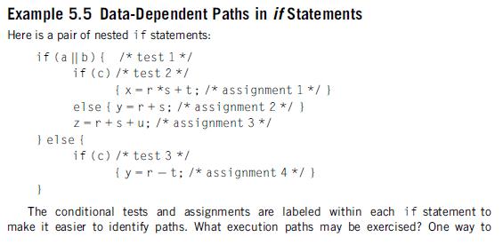
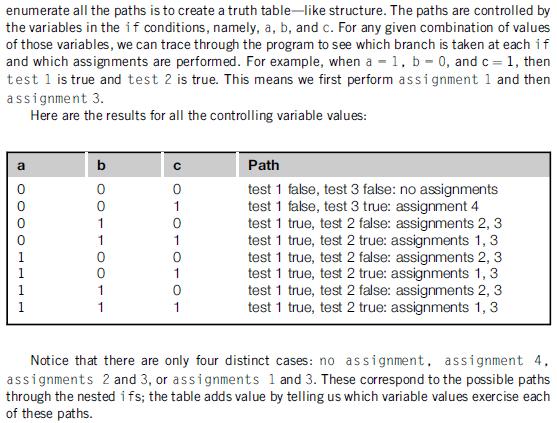
Draw a data flow graph for the code fragment of Example 5.5. Assign an order of execution to the nodes in the graph so that no more than four registers are required. Explain how you arrived at your solution using the structure of the data flow graph. Example 5.5 Data-Dependent Paths in if
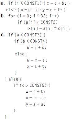
Determine the longest path through each code fragment, assuming that all statements can be executed in equal time and that all branch directions are equally probable. a. if (i < CONST1) {x a+b; } else {x c-d; y-e+f; } b. for (i=0; i < 32; i++) - if (a[i] CONST5) { w-r+t; x-r s y-s+u;
For each code fragment, list the sets of variable values required to execute each assignment statement at least once. Reaching all assignments may require multiple independent executions of the code. a. if (a> 0) else { x-5; if (b < 0) x-7; b. if (a b) { if (c) d) x-1; else x-23 x-x+1; }
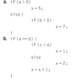
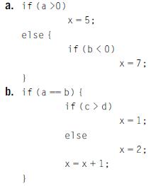
Determine the shortest path through each code fragment, assuming that all statements can be executed in equal time and that all branch directions are equally probable. The first branch is always taken. a. if (a >0) x=5; else { if (b < 0) b. if (a b) { if (c> d) x=7; x-1: else x-2;
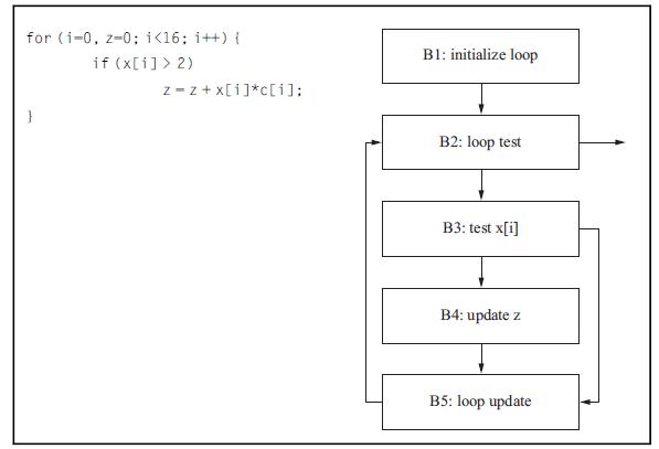
You are given this program and its flowchart:The execution time of the blocks is: B1 = 6 cycles, B2 = 2 if branch taken, 5 if not taken, B3 = 3 if branch taken, 6 if not taken, B4 = 7, B5 = 1a. What is the maximum number of times that each block in your flowchart executed?b. What is the minimum
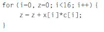
You are given this program:A cache miss costs 6 clock cycles and a cache hit costs 2 clock cycles.Assume that x and c do not interfere in the cache and that z and i are held in registers. If the cache line can hold W words, plot Ta, the total number of cycles required for the array accesses (x and
Write the branch tests for each conditional.a. if ((a > 0) && (b < 0)) f1();b. if ((a == 5) && !c) f2();c. if ((b jj c) && (a != d)) f3();
The loop appearing below is executed on a machine that has a 1-K-word data cache with four words per cache line.a. How must x and a be placed relative to each other in memory to produce a conflict miss every time the inner loop’s body is executed?b. How must x and a be placed relative to each
Explain why the person generating clear-box program tests should not be the person who wrote the code being tested.
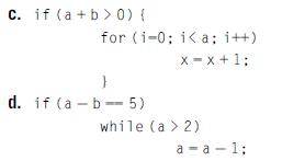
Find the cyclomatic complexity of the CDFGs for each of the code fragments given below. a. if (ab) { if (cd) else x=1; x-2;
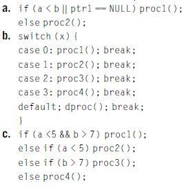
Use the branch condition testing strategy to determine a set of tests for eachof the following statements. a. if (a 7) procl(); else if (a 7) proc3(); else proc4();
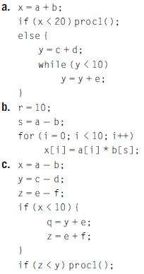
Find all the def-use pairs for each code fragment given below. a. x=a+b; if (x < 20) procl(); else { y-c+d; while (y
For each of the code fragments of Q5-28, determine values for the variables that will cause each def-use pair to be exercised at least once.Data from Q5-28Find all the def-use pairs for each code fragment given below. a. x=a+b; if (x < 20) procl(); else { y-c+d; while (y
Write C++ code for an FIR filter using a class to implement the filter.Implement as many member functions as possible as inline functions. Measure the execution time of the filter and compare to the C implementation.
Briefly describe the distinction between requirements and specification.
Give an example of a requirement on a computer printer.
Give an example of a requirement on a digital still camera.
How could a security breach on a commercial airliner’sWi-Fi network result in a safety problem for the airplane?
Given an example of a specification on a computer printer, giving both type of specification and any required values. Take your example from an existing product and identify that product.
Given an example of a specification on a digital still camera, giving both type of specification and any required values. Take your example from an existing product and identify that product.
Briefly describe the distinction between specification and architecture.
At what stage of the design methodology would we determine what type of CPU to use (8-bit vs 16-bit vs 32-bit, which model of a particular type of CPU, etc.)?
At what stage of the design methodology would we choose a programming language?
Should an embedded computing system include software designed in more than one programming language? Justify your answer.
At what stage of the design methodology would we test our design for functional correctness?
Compare and contrast top-down and bottom-up design.
Give an example of a design problem that is best solved using top-down techniques.
Give an example of a design problem that is best solved using bottom-up techniques.
Provide a concrete example of how bottom-up information from the software programming phase of design may be useful in refining the architectural design.
Give a concrete example of how bottom-up information from I/O device hardware design may be useful in refining the architectural design.
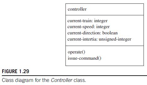
Create a UML state diagram for the issue-command() behavior of the Controller class of Fig. 1.29. controller current-train: integer current-speed: integer current-direction: boolean current-intertia: unsigned-integer operate() issue-command() FIGURE 1.29 Class diagram for the Controller class.
Show how a Set-speed command flows through the refined class structure described in Fig. 1.19, moving from a change on the front panel to the required changes on the train:a. Show it in the form of a collaboration diagram.b. Show it in the form of a sequence diagram. controller current-train:
Showing 2400 - 2500
of 5433
First
18
19
20
21
22
23
24
25
26
27
28
29
30
31
32
Last
Step by Step Answers