New Semester
Started
Get
50% OFF
Study Help!
--h --m --s
Claim Now
Question Answers
Textbooks
Find textbooks, questions and answers
Oops, something went wrong!
Change your search query and then try again
S
Books
FREE
Study Help
Expert Questions
Accounting
General Management
Mathematics
Finance
Organizational Behaviour
Law
Physics
Operating System
Management Leadership
Sociology
Programming
Marketing
Database
Computer Network
Economics
Textbooks Solutions
Accounting
Managerial Accounting
Management Leadership
Cost Accounting
Statistics
Business Law
Corporate Finance
Finance
Economics
Auditing
Tutors
Online Tutors
Find a Tutor
Hire a Tutor
Become a Tutor
AI Tutor
AI Study Planner
NEW
Sell Books
Search
Search
Sign In
Register
study help
computer science
systems analysis design
Computers As Components Principles Of Embedded Computing System Design 4th Edition Marilyn Wolf - Solutions
Using your favorite operating system, write code to spawn a process that writes “Hello, world” to the screen or flashes an LED, depending on your available output devices.
Name an embedded system that requires both periodic and aperiodic computation.
Build a small serial port device that lights LEDs based on the last character written to the serial port. Create a process that will light LEDs based on keyboard input.
An audio system processes samples at a rate of 44.1 kHz. At what rate could we sample the system’s front panel to both simplify analysis of the system schedule and provide adequate response to the user’s front panel requests?
Write a driver for an I/O device.
Draw a UML class diagram for a process in an operating system. The process class should include the necessary attributes and behaviors required of a typical process.
Write context switch code for your favorite CPU.
Draw a task graph in which P1 and P2 each process separate inputs and then pass their results onto P3 for further processing.
Measure context switching overhead on an operating system.
Compute the utilization for these task sets:a. P1: period = 1 s, execution time = 10 ms; P2: period = 100 ms, execution time 10 msb. P1: period 100 ms, execution time = 25 ms; P2: period = 80 ms, execution time = 15 ms; P3: period = 40 ms, execution time = 5 ms.c. P1: period 10 ms, execution time =
Using a CPU that runs an operating system that uses RMS, try to get the CPU utilization up to 100%. Vary the data arrival times to test the robustness of the system.
What factors provide a lower bound on the period at which the system timer interrupts for preemptive context switching?
Using a CPU that runs an operating system that uses EDF, try to get the CPU utilization as close to 100% as possible without failing. Try a variety of data arrival times to determine how sensitive your process set is to environmental variations.
What factors provide an upper bound on the period at which the system timer interrupts for preemptive context switching?
Measure the effect of cache conflicts on real-time execution time. First, set up your system to measure the execution time of your real-time process. Next, add a background process to the system. One version of the background process should do nothing, another should do some work that will
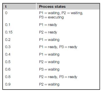
A set of processes changes state as shown over the interval [0, 1 ms]. P1 has the highest priority and P3 has the lowest priority. Draw a UML sequence diagram showing the state of all the processes during this interval. 0 0.1 0.15 0.2 0.3 0.4 0.5 0.6 0.8 0.9 Process states P1 waiting, P2 = waiting,
What is the distinction between the ready and waiting states of process scheduling?
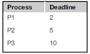
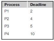
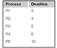
For the following periodic processes, what is the shortest interval we must examine to see all combinations of deadlines?a.b.c. Process P1 P2 Deadline 2 5 P3 10
Provide examples ofa. blocking interprocess communication;b. nonblocking interprocess communication.
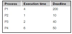
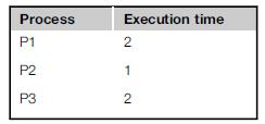
Consider the following system of periodic processes executing on a single CPU:Can we add another instance of P1 to the system and meet all the deadlines using RMS? Process Execution time Deadline 200 P1 4 P2 1 10 P3 2 40 P4 6 50
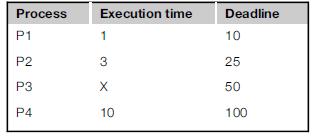
Given the following set of periodic processes running on a single CPU (P1 has highest priority), what is the maximum execution time x of P3 for which all the processes will be schedulable using EDF? Process Execution time Deadline 10 P1 1 P2 3 25 P3 X 50 P4 10 100
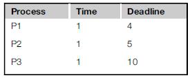
A set of periodic processes is scheduled using RMS; P1 has the highest priority. For the process execution times and periods shown below, show the state of the processes at the critical instant for each of these processes.a. P1b. P2c. P3 Process P1 Time Deadline 1 4 P2 1 5 P3 1 10
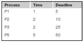
For the given periodic process execution times and periods (P1 has the highest priority), show how much CPU time of higher-priority processes will be required during one period of each of the following processes:a. P1b. P2c. P3d. P4 Process P1 P2 P3 P5 Time Deadline 1 5 225 10 25 50
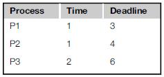
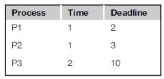
For the periodic processes shown below:a. Schedule the processes using an RMS policy.b. Schedule the processes using an EDF policy.In each case, compute the schedule for an interval equal to the least common multiple of the periods of the processes. P1 has the highest priority and time starts at t
For the periodic processes shown below:a. Schedule the processes using an RMS policy.b. Schedule the processes using an EDF policy.In each case, compute the schedule for an interval equal to the least common multiple of the periods of the processes. P1 has the highest priority and time starts at t
For the periodic processes shown below:a. Schedule the processes using an RMS policy.b. Schedule the processes using an EDF policy.In each case, compute the schedule for an interval equal to the leastcommon multiple of the periods of the processes. P1 has the highest priority and time starts at t =
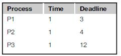
For the given set of periodic processes, all of which share the same deadline of 12:a. Schedule the processes for the given arrival times using standard ratemonotonic scheduling (no data dependencies).b. Schedule the processes taking advantage of the data dependencies. By how much is the CPU
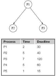
For the periodic processes given below, find a valid schedulea. using standard RMS;b. adding one unit of overhead for each context switch. 22 P2 P1 P3 Process P1 P2 P3 Time Deadline 2 30 57 40 120 P4 5 60 P5 1 15
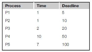
For the periodic processes and deadlines given below:a. Schedule the processes using RMS.b. Schedule using EDF and compare the number of context switches required for EDF and RMS Process Time Deadline P1 1 5 P2 1 10 P3 2 20 P4 10 50 P5 7 100
If you wanted to reduce the cache conflicts between the most computationally intensive parts of two processes, what are two ways that you could control the locations of the processes’ cache footprints?
A system has two processes P1 and P2 with P1 having higher priority.They share an I/O device ADC. If P2 acquires the ADC from the RTOS and P1 becomes ready, how does the RTOS schedule the processes using priority inheritance?
Explain the roles of interrupt service routines and interrupt service handlers in interrupt handling.
Briefly explain the dual-kernel approach to RTOS design.
What are the kernel-level units of execution in WinCE?
How would you use the ADPCM method to encode an unvarying (DC) signal with the coding alphabet {- 3, - 2, -1, 1, 2, 3}?
Briefly describe the differences between the waterfall and spiral development models.
Draw a diagram showing the developmental steps of one of the projects you recently designed. Which development model did you follow (waterfall, spiral, etc.)?
What skills might be useful in a cross-functional team that is responsible for designing a set-top box?
Find a detailed description of a system of interest to you. Write your own description of what it does and how it works.
Provide realistic examples of how a requirements document may be:a. ambiguousb. incorrectc. incompleted. unverifiable
How can poor specifications lead to poor quality codeddo aspects of a poorly constructed specification necessarily lead to bad software?
Give examples of the component networks in a federated network for an automobile.
Build an experimental setup that lets you monitor messages on an embedded network.
Draw a UML sequence diagram for a use case of a passenger sitting in a car seat and buckling the seat belt. The sequence diagram should include the passenger, the seat’s passenger sensor, the seat belt fastening sensor, the seat belt controller, and the seat belt fastened indicator (which is on
Build a CAN bus monitoring system.
Draw a UML sequence diagram for a use case for an attack on a car through its telematics unit. The attack first modifies the software on the telematics unit, then modifies software on the brake unit. The sequence diagram should include the telematics unit, the brake unit, and the attacker.
Describe an IC bus at the following OSI-compliant levels of detail:a. physicalb. data linkc. networkd. transport
Determine how much logic in an FPGA must be devoted to a PCIe bus interface and how much would be left for an accelerator core.
You are designing an embedded system using an Intel Atom as a host. Does it make sense to add an accelerator to implement the function z = ax + by + c? Explain.
Develop a debugging scheme for an accelerator. Determine how you would easily enter data into the accelerator and easily observe its behavior. You will need to verify the system thoroughly, starting with basic communication and going through algorithmic verification.
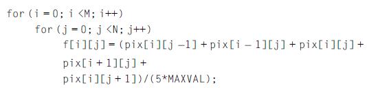
You are designing an accelerated system that performs the following function as its main task:Assume that the accelerator has the entire pix and f arrays in its internal memory during the entire computationdpix is read into the accelerator before the operations begin and f is written out after all
You are designing an embedded system using an embedded processor with no floating-point support as host. Does it make sense to add an accelerator to implement the floating-point function S = A sin(2πf + ϕ)? Explain.
Develop a generic streaming interface for an accelerator. The interface should allow streaming data to be read by the accelerator from the host’s memory. It should also allow streaming data to be written from the accelerator back to memory. The interface should include a host-side mechanism for
You are designing an embedded system using a high-performance embedded processor with floating point as host. Does it make sense to add an accelerator to implement the floating-point function S = A sin(2πf + ϕ)? Explain.
Assume you want to use random tests on an FIR filter program. How would you know when the program under test is executing correctly?
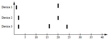
Three devices are attached to a microprocessor: Device 1 has highest priority and device 3 has lowest priority. Each device’s interrupt handler takes 5 time units to execute. Show what interrupt handler (if any) is executing at each time given the sequence of device interrupts displayed below.
Provide examples of how each of the following can occur in a typical program:a. compulsory missb. capacity missc. conflict miss
Draw a UML sequence diagram for an interrupt-driven write of a device. The diagram should include the background program, the handler, and the device.
Draw a UML sequence diagram for a vectored interrupt-driven read of a device. The diagram should include the background program, the interrupt vector table, the handler, and the device.
Draw a UML sequence diagram for copying characters from an input to an output device using interrupt-driven I/O. The diagram should include the two devices and the two I/O handlers.
Draw a UML sequence diagram of a higher-priority interrupt that happens during a lower-priority interrupt handler. The diagram should include the device, the two handlers, and the background program.
Draw a UML sequence diagram of a lower-priority interrupt that happens during a higher-priority interrupt handler. The diagram should include the device, the two handlers, and the background program.
Draw a UML sequence diagram of a nonmaskable interrupt that happens during a low-priority interrupt handler. The diagram should include the device, the two handlers, and the background program.
Draw a UML state diagram for the steps performed by an ARM7 when it responds to an interrupt.
Draw a UML sequence diagram that shows how an ARM processor goes into supervisor mode. The diagram should include the supervisor mode program and the user mode program.
Give three examples of typical types of exceptions handled by CPUs.
What are traps used for?
Draw a UML sequence diagram that shows how an ARM processor handles a floating-point exception. The diagram should include the user program, the exception handler, and the exception handler table.
What is the average memory access time of a machine whose hit rate is 96%, with a cache access time of 3 ns and a main memory access time of 70 ns?
If we want an average memory access time of 6.5 ns, our cache access time is 5 ns, and our main memory access time is 80 ns, what cache hit rate must we achieve?
In the two-way, set-associative cache with four banks of Example 3.8, show the state of the cache after each memory access, as was done for the directmapped cache. Use an LRU replacement policy.
The following code is executed by an ARM processor with each instruction executed exactly once:Show the contents of the instruction cache for these configurations, assuming each line holds one ARM instruction:a. direct-mapped, two linesb. direct-mapped, four linesc. two-way set-associative, two
Show a UML state diagram for a paged address translation using a flat page table.
Show a UML state diagram for a paged address translation using a three level, tree-structured page table.
What are the stages in an ARM 7 pipeline?
What are the stages in the C55x pipeline?
What is the difference between latency and throughput?
Draw a pipeline diagram for an ARM7 pipeline’s execution of three fictional instructions: aa, bb, and cc. The aa instruction always requires two cycles to complete the execute stage. The cc instruction takes two cycles to complete the execute stage if the previous instruction was a bb
Draw two pipeline diagrams showing what happens when an ARM BZ instruction is taken and not taken, respectively.
Name three mechanisms by which a CMOS microprocessor consumes power.
Provide a user-level example ofa. static power managementb. dynamic power management
Why cannot you use the same mechanism to return from a sleep power saving state as you do from an idle power-saving state?
Name three major components of a generic computing platform.
Use a logic analyzer to view system activity on your bus.
If your CPU has a pipeline that gives different execution times when a branch is taken or not taken, write a program in which these branches take different amounts of time. Use a CPU simulator to observe the behavior of the program.
Write ARM code that tests a register at location ds1 and continues execution only when the register is nonzero.
Measure the time required to respond to an interrupt.
Write ARM code that waits for the low-order bit of device register ds1 to become 1 and then reads a value from register dd1.
Implement peek() and poke() in assembly language for ARM.
Draw a UML sequence diagram for a busy-wait read of a device. The diagram should include the program running on the CPU and the device.
Draw a UML sequence diagram for a busy-wait write of a device. The diagram should include the program running on the CPU and the device.
Draw a UML sequence diagram for copying characters from an input to an output device using busy-wait I/O. The diagram should include the two devices and the two busy-wait I/O handlers.
What role does the HAL play in the platform?
If your logic analyzer is capable of on-the-fly disassembly, use it to display bus activity in the form of instructions, rather than simply 1s and 0s.
Draw UML state diagrams for device 1 and device 2 in a four-cycle handshake.
Attach LEDs to your system bus so that you can monitor its activity. For example, use an LED to monitor the read/write line on the bus.
Describe the role of these signals in a bus:a. R/W’b. data readyc. clock
Design logic to interface an I/O device to your microprocessor.
Draw a UML sequence diagram that shows a four-cycle handshake between a bus master and a device.
Use a data dump program to study the format of data on a flash memory card used as a file system.
Showing 2300 - 2400
of 5433
First
17
18
19
20
21
22
23
24
25
26
27
28
29
30
31
Last
Step by Step Answers