

Consider the block diagram of a robot-arm control system shown in Fig. P8.6-4. This system is described
Question:
Consider the block diagram of a robot-arm control system shown in Fig. P8.6-4. This system is described in Problem 1.5-4. Let \(T=0.1\). It was shown in Problem 4.3-8 that
\[
G(z)=\frac{z-1}{z} z\left[\frac{2}{s^{2}(0.5 s+1)}ight]=\frac{0.01873 z+0.01752}{(z-1)(z-0.8187)}
\]
The frequency response for \({ }_{G(z)}\) is given in Table P7-23. Note that the sensor gain \(H=0.07\) is not included in this table.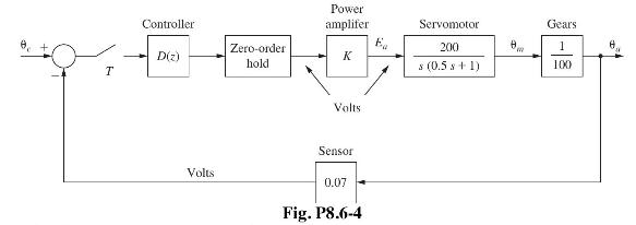
(a) Find the system phase margin with
\[
D(z)=1^{.}
\]
(b) Design a phase-lag controller with the dc gain of 10 that yields a system phase margin of \(45^{\circ}\).
(c) Design a phase-lead controller with the dc gain of 10 that yields a system phase margin of \(45^{\circ}\).
(d) Using MATLAB, find the step response for the systems of parts (b) and (c), with \(\theta_{c}(t)=0.07 u(t)\). Compare the rise times and the percent overshoot for the two systems. The percent overshoot is defined as
\[
\text { percent overshoot }=\frac{\text { maximum value }- \text { final value }}{\text { final value }} \times 100
\]
Problem 1.5-4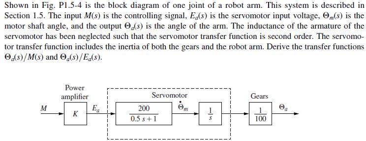
Step by Step Answer:


Digital Control System Analysis And Design
ISBN: 9780132938310
4th Edition
Authors: Charles Phillips, H. Nagle, Aranya Chakrabortty
