New Semester
Started
Get
50% OFF
Study Help!
--h --m --s
Claim Now
Question Answers
Textbooks
Find textbooks, questions and answers
Oops, something went wrong!
Change your search query and then try again
S
Books
FREE
Study Help
Expert Questions
Accounting
General Management
Mathematics
Finance
Organizational Behaviour
Law
Physics
Operating System
Management Leadership
Sociology
Programming
Marketing
Database
Computer Network
Economics
Textbooks Solutions
Accounting
Managerial Accounting
Management Leadership
Cost Accounting
Statistics
Business Law
Corporate Finance
Finance
Economics
Auditing
Tutors
Online Tutors
Find a Tutor
Hire a Tutor
Become a Tutor
AI Tutor
AI Study Planner
NEW
Sell Books
Search
Search
Sign In
Register
study help
engineering
mechanics of materials
Mechanics Of Materials 11th Edition Russell C. Hibbeler - Solutions
The 304 stainless steel band initially fits snugly around the smooth rigid cylinder. If the band is then subjected to a nonlinear temperature drop of \(\Delta T=20 \sin ^{2} \theta{ }^{\circ} \mathrm{F}\), where \(\theta\) is in radians, determine the circumferential stress in the band. 10 in. in.
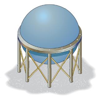
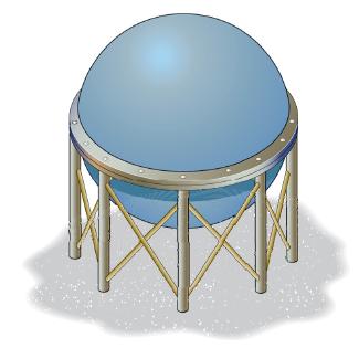
The spherical gas tank is fabricated by bolting together two hemispherical thin shells of thickness \(30 \mathrm{~mm}\). If the gas contained in the tank is under a pressure of \(2 \mathrm{MPa}\), determine the normal stress developed in the wall of the tank and in each of the bolts.The tank has an
The spherical gas tank is fabricated by bolting together two hemispherical thin shells. If the 8 -m inner diameter tank is to be designed to withstand a pressure of \(2 \mathrm{MPa}\), determine the minimum wall thickness of the tank and the minimum number of 25 - \(\mathrm{mm}\)-diameter bolts
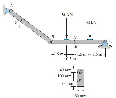
Determine the state of stress acting at point \(E\). Show the results on a differential element at this point. A 3 90 kN 30 kN B D |-1.5m+ E -1.5 m 1.5 m--1.5 m- 0.5 m 40 mnt D 100 mm E 60 mm 80 mm
The joint is subjected to a force of \(P=200 \mathrm{lb}\) and \(F=150 \mathrm{lb}\). Determine the state of stress at points \(A\) and \(B\), and sketch the results on differential elements located at these points. The member has a rectangular cross section of width 0.75 in. and thickness 0.5 in.
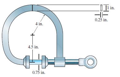
The C-clamp applies a compressive stress on the cylindrical block of 80 psi. Determine the maximum tensile and compressive stress developed in the clamp. t 4 in. 4.5 in. | 11 in. 0.25 in. 0.75 in.
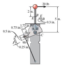
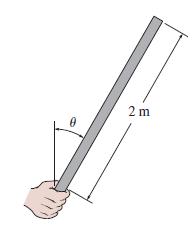
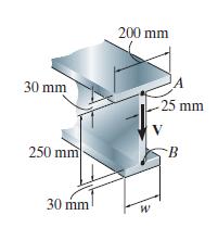
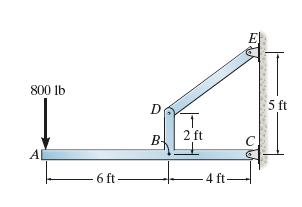
The control lever is subjected to a horizontal force of \(20 \mathrm{lb}\) on the handle. Determine the state of stress at points \(A\) and \(B\). Sketch the results on differential elements located at each of these points. The assembly is pin connected at \(C\) and attached to a cable at \(D\).
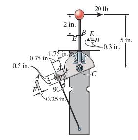
The control lever is subjected to a horizontal force of \(20 \mathrm{lb}\) on the handle. Determine the state of stress at points \(E\) and \(F\). Sketch the results on differential elements located at each of these points. The assembly is pin connected at \(C\) and attached to a cable at \(D\).
The coping saw has an adjustable blade that is tightened with a tension of \(40 \mathrm{~N}\). Determine the state of stress in the frame at points \(A\) and \(B\). 100 mm -75 mm- 8 mm 3 mm: A 3 mm B 50 mm 8 mm
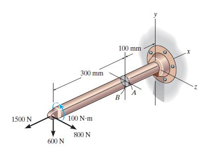
The rod has a diameter of \(40 \mathrm{~mm}\). Determine the stress components that act at point \(B\), and show the results on a volume element located at this point. 1500 N 300 mm 600 N 100 Nm 800 N 100 mm B y 2
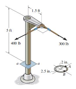
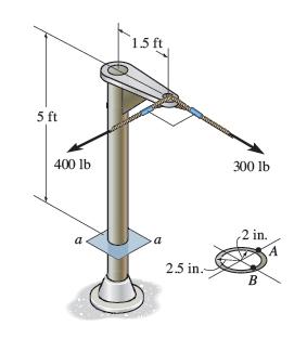
Determine the state of stress at point \(A\) on the cross section of the post at section \(a-a\). Indicate the results on a differential element at the point. 5ft 400 lb a 1.5 ft 300 lb a 2.5 in. 2 in. A B
Determine the state of stress at point \(B\) on the cross section of the post at section \(a-a\). Indicate the results on a differential element at the point. 5 ft 400 lb 1.5 ft 300 lb a a 2.5 in.- 2 in. B
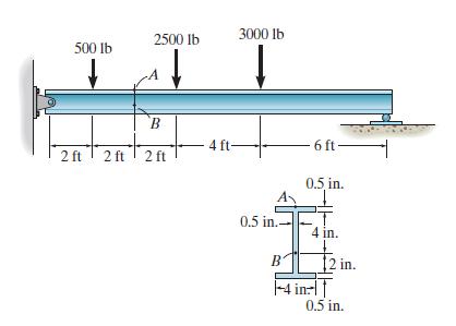
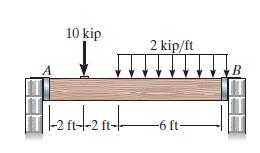
The wide-flange beam is subjected to the loading shown. Determine the stress components at points \(A\) and \(B\) and show the results on a volume element at each of these points. 2500 lb 3000 lb 500 lb B 4 ft- 6 ft- 2 ft 2 ft 2 ft 0.5 in. 0.5 in.- 4 in. B 12 in. -4 in: 0.5 in.
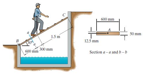
If the \(75-\mathrm{kg}\) man stands in the position shown, determine the state of stress at point \(A\) on the cross section of the plank at section \(a-a\). The center of gravity of the man is at \(G\). Assume that the contact point at \(C\) is smooth. a 1.5 m 12.5 mm 600 mm 300 mm 600 mm Section
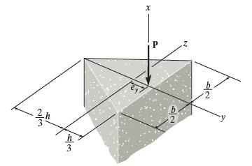
The eccentric force \(\mathbf{P}\) is applied at a distance \(e_{y}\) from the centroid on the concrete support shown. Determine the range along the \(y\) axis where \(\mathbf{P}\) can be applied on the cross section so that no tensile stress is developed in the material. 2/3 x 3 P 12
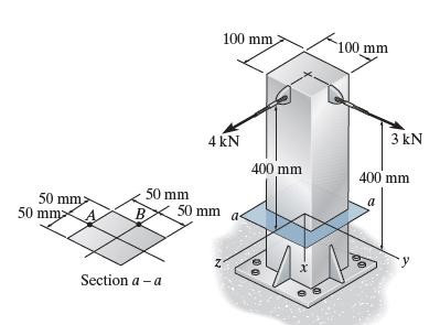
Determine the state of stress at point \(A\) on the cross section of the post at section \(a-a\). Indicate the results on a differential element at the point. 100 mm 100 mm 4 kN 3 kN 400 mm 400 mm a 50 mm 50 mm 50 mm 50 mm B Section a-a 00
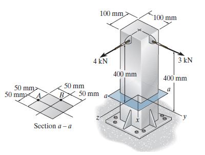
Determine the state of stress at point \(B\) on the cross section of the post at section \(a-a\). Indicate the results on a differential element at the point. 100 mm 100 mm 4 kN 50 mm 50 mm 50 mm B 50 mm Section a-a 3 kN 400 mm 400 mm 100
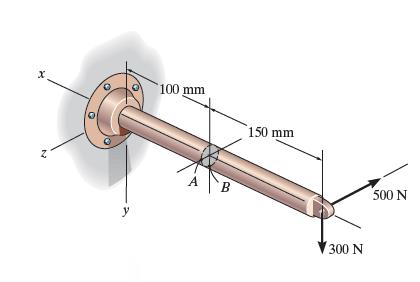
The bar has a diameter of \(40 \mathrm{~mm}\). If it is subjected to the two force components at its end as shown, determine the state of stress at point \(A\), and show the results on a differential volume element located at this point. x 100 mm 150 mm Z A B 300 N 500 N
The gas storage tank is fabricated by bolting together two half cylindrical thin shells and two hemispherical shells as shown. If the tank is designed to withstand a pressure of \(3 \mathrm{MPa}\), determine the required minimum thickness of the cylindrical and hemispherical shells and the minimum
The gas storage tank is fabricated by bolting together two half cylindrical thin shells and two hemispherical shells as shown. If the tank is designed to withstand a pressure of \(3 \mathrm{MPa}\), determine the required minimum thickness of the cylindrical and hemispherical shells and the minimum
The cylindrical tank is fabricated by welding a strip of thin plate helically, making an angle \(\theta\) with the longitudinal axis of the tank. If the strip has a width \(w\) and thickness \(t\), and the gas within the tank of diameter \(d\) is subjected to a pressure \(p\), show that the normal
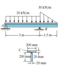
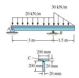
Determine the maximum shear stress in the T-beam at the section where the internal shear is maximum. A 20 kN/m 30 kN/m -3 m- C 200 mm -B +1.5 m 1.5m-| 200 mm 20 mm --20 mm
Determine the shear stress at point C in the T-beam where the internal shear is maximum. Show the result on a volume element at this point. A 20 kN/m 30 kN/m 3 m- 200 mm B -1.5 m- 200 mm 20 mm -20 mm
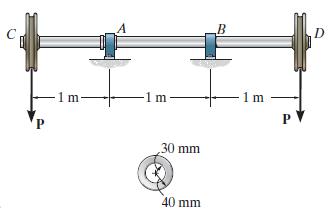
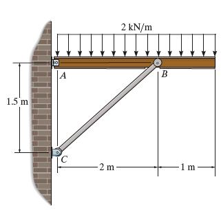
The shaft is supported by a thrust bearing at A and a journal bearing at B. If the shaft is made from a material having an allowable shear stress of τallow = 75 MPa, determine the maximum value for P. 1 m- -1 m- 1 m PV 30 mm 40 mm D
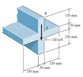
The strut is subjected to a vertical shear of V = 130 kN. Plot the intensity of the shear-stress distribution acting over the cross-sectional area, and determine the resultant shear force developed in the vertical segment AB. B 150 mm 50 mm A 150 mm V= = 130 kN 50 mm 150 mm 150 mm
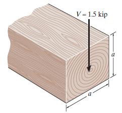
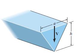
The beam has a square cross section and is made of wood having an allowable shear stress of τallow = 1.4 ksi. If it is subjected to a shear of V = 1.5 kip, determine the smallest dimension a of its sides. V-1.5 kip a
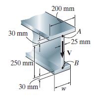
If the wide-ange beam is subjected to a shear of \(V=30 \mathrm{kN}\), determine the maximum shear stress in the beam. Set \(w=\) \(200 \mathrm{~mm}\). The neutral axis is located at \(\bar{y}=0.1747 \mathrm{~m}\) from the bottom and \(I_{N A}=0.2182\left(10^{-3}\right) \mathrm{m}^{4}\). 200 mm 30
If the wide-ange beam is subjected to a shear of \(V=30 \mathrm{kN}\), determine the shear force resisted by the web of the beam. Set \(w=200 \mathrm{~mm}\). The neutral axis is located at \(\bar{y}=0.1747 \mathrm{~m}\) from the bottom and \(I_{N A}=0.2182\left(10^{-3}\right) \mathrm{m}^{4}\). 200
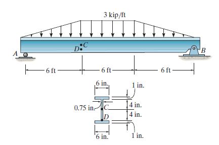
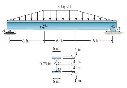
Determine the shear stress at points \(C\) and \(D\) located on the web of the beam. 6ft- D:C 3 kip/ft 0.75 in. 6 ft. 6 ft .6 in.. 1 in. 4 in. D 4 in. '6 in.' 1 in.
Determine the maximum shear stress acting in the beam at the critical section where the internal shear force is maximum. 6 ft D:C 3 kip/ft -6 ft- .6 in.. 1 in. 0.75 in C [4 in. D [4 in. '6 in. 1 in. 6 ft- B
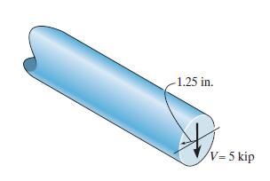
The steel rod has a radius of 1.25 in. If it is subjected to a shear of \(V=5\) kip, determine the maximum shear stress. 1.25 in. V-5 kip
A member has a cross section in the form of an equilateral triangle. If it is subjected to a shear force \(\mathbf{V}\), determine the maximum average shear stress in the member using the shear formula. Should the shear formula actually be used to predict this value? Explain. h
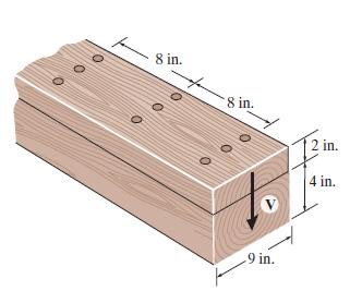
The beam is constructed from two boards fastened together at the top and bottom with three rows of nails spaced every 8 in. If each nail can support a \(300-\) lb shear force, determine the maximum shear force \(V\) that can be applied to the beam. 8 in. 8 in. 2 in. to 9 in. 4 in.
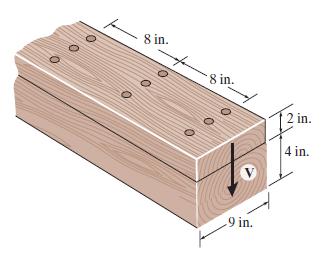
The beam is constructed from two boards fastened together at the top and bottom with three rows of nails spaced every \(8 \mathrm{in}\). If an internal shear force of \(V=800 \mathrm{lb}\) is applied to the boards, determine the shear force resisted by each nail. 8 in. 8 in. 2 in. 4 in. 9 in.
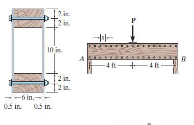
The double-web girder is constructed from two plywood sheets that are secured to wood members at its top and bottom. If each fastener can support \(600 \mathrm{lb}\) in single shear, determine the required spacing \(s\) of the fasteners needed to support the loading \(P=3000 \mathrm{lb}\). Assume
The double-web girder is constructed from two plywood sheets that are secured to wood members at its top and bottom. The allowable bending stress for the wood is \(\sigma_{\text {allow }}=\) \(8 \mathrm{ksi}\) and the allowable shear stress is \(\tau_{\text {allow }}=3\) ksi. If the fasteners are
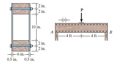
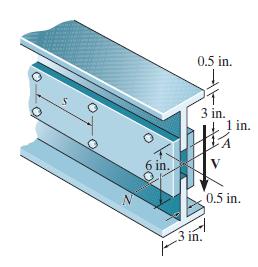
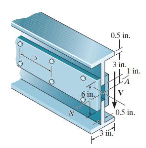
The beam is fabricated from two equivalent structural tees and two plates. Each plate has a height of 6 in. and a thickness of 0.5 in. If a shear of \(V=50\) kip is applied to the cross section, determine the maximum spacing of the bolts. Each bolt can resist a shear force of 15 kip. 0.5 in. T 3
The beam is fabricated from two equivalent structural tees and two plates. Each plate has a height of 6 in. and a thickness of 0.5 in. If the bolts are spaced at \(s=8\) in., determine the maximum shear force \(V\) that can be applied to the cross section. Each bolt can resist a shear force of 15
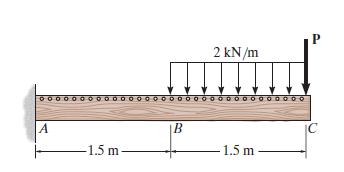
Determine the average shear stress developed in the nails within region \(A B\) of the beam. The nails are located on each side of the beam and are spaced \(100 \mathrm{~mm}\) apart. Each nail has a diameter of \(4 \mathrm{~mm}\). Take \(P=2 \mathrm{kN}\). A -1.5 m B 2 kN/m C 1.5 m
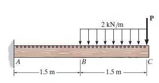
The nails are on both sides of the cantilever beam and each can resist a shear of \(2 \mathrm{kN}\). In addition to the distributed loading, determine the maximum load \(P\) that can be applied to the end of the beam. The nails are spaced \(100 \mathrm{~mm}\) apart and the allowable shear stress
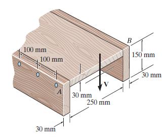
The beam is subjected to a shear of \(V=800 \mathrm{~N}\). Determine the average shear stress developed in the nails along the sides \(A\) and \(B\) if the nails are spaced \(s=100 \mathrm{~mm}\) apart. Each nail has a diameter of \(2 \mathrm{~mm}\). 100 mm 100 mm 30 mm 30 mm 250 mm B 150 mm 30 mm
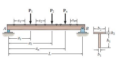
The timber T-beam is subjected to a load consisting of \(n\) concentrated forces, \(P_{n}\). If the allowable shear \(V_{\text {nail }}\) for each of the nails is known, write a computer program that will specify the nail spacing between each force. Show an application of the program using the
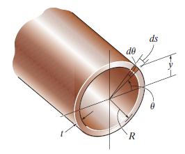
Determine the shear stress variation over the cross section of the thin-walled tube as a function of elevation y and show that \(\tau_{\max }=2 V / A\), where \(A=2 \pi r\). Choose a differential area element \(d A=R t d \theta\). Using \(d Q=y d A\), formulate \(Q\) for a circular section from
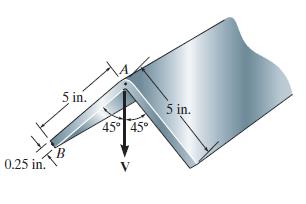
The angle is subjected to a shear force of \(V=2\) kip. Sketch the distribution of shear flow along the leg \(A B\). Indicate numerical values at all peaks. 0.25 in. 5 in. 45 45 5 in.
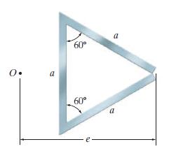
Determine the location \(e\) of the shear center, point \(O\), for the thin-walled member having the cross section shown. a 60 a 60 a
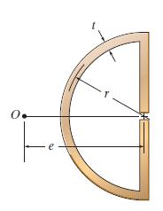
Determine the location \(e\) of the shear center, point \(O\), for the beam having the cross section shown. The thickness is \(t\).
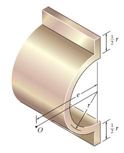
Determine the location \(e\) of the shear center, point \(O\), for the beam having the cross section shown. The thickness is \(t\). T
Determine the shear and moment in the shaft as functions of x within the region 125 mm x 725 mm, and then draw the shear and moment diagrams for the shaft. The bearings at A and B exert only vertical reactions on the shaft. A 800 N 1500 N 600 mm 75 mm 125 mm B
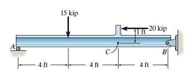
Draw the shear and moment diagrams for the beam.The 20-kip load must be replaced by equivalent loadings at point C on the axis of the beam. A 15 kip 11 ft 20 kip 4 ft 4 ft 4 ft B
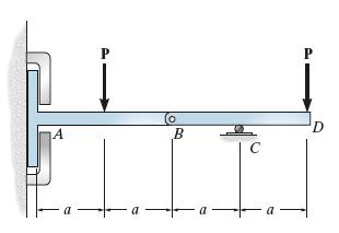
Draw the shear and moment diagrams for the compound beam. It is supported by a smooth plate at A which slides within the groove and so it cannot support a vertical force, although it can support a moment and axial load. P A B C a a a a P
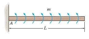
The beam is subjected to the uniformly distributed moment m (moment/length). Draw the shear and moment diagrams for the beam. A L m
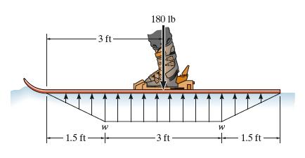
The ski supports the 180-lb weight of the man. If the snow loading on its bottom surface is trapezoidal as shown, determine the intensity w, and then draw the shear and moment diagrams for the ski. 3 ft- 180 lb 1.5 ft- W W -3 ft- 1.5 ft
The overhang beam has been fabricated with a projected arm BD on it. Draw the shear and moment diagrams for the beam ABC if it supports a load of 800 lb. The loading in the supporting strut DE must be replaced by equivalent loads at point B on the axis of the beam. 800 lb D T 2 ft B AL 6 ft 4 ft 5
The beam is subjected to the uniform distributed load shown. Draw the shear and moment diagrams for the beam. 1.5 m A 2 kN/m B -2 m 1 m
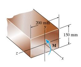
A member having the dimensions shown is used to resist an internal bending moment of M = 90 kN⋅m. Determine the maximum stress in the member if the moment is applied (a)about the z axis (as shown), (b) about the y axis. Sketch the stress distribution for each case. 200 mm M 150 mm
If the beam is subjected to an internal moment of M = 100kip•ft, determine the maximum tensile and compressive bending stress in the beam. 3 in. 3 in. 1.5 in. M 6 in. 2 in.
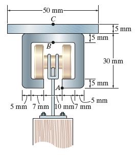
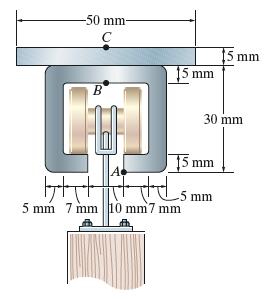
The channel strut is used as a guide rail for a trolley.If the maximum moment in the strut is M = 30N⋅m, determine the bending stress at points A, B, and C. -50 mm- C B 15 mm 15 mm 30 mm 15 mm +5 5 mm 7 mm 10 mm7 mm 5 mm
The channel strut is used as a guide rail for a trolley. If the allowable bending stress for the material is σallow = 175MPa, determine the maximum allowable bending moment in the strut. -50 mm- C B 15 mm 15 mm 30 mm 15 mm 5 mm 7 mm 10 mm7 mm smm
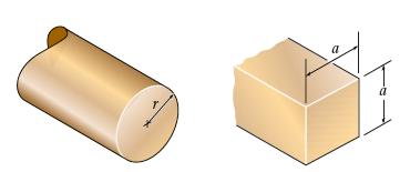
Determine the dimension a of a beam having a square cross section in terms of the radius r of a beam with a circular cross section if both beams are subjected to the same internal moment which results in the same maximum bending stress.
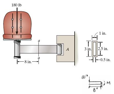
The chair is supported by a fixed arm at A. If the load on the chair is 180 lb and the arm is a hollow tube section having the dimensions shown, determine the maximum bending stress at section a-a. 180 lb 8 in. a A I 1 in. 180 3 in. 2.5 in. -0.5 in. 8"
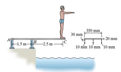
The man has a mass of 78 kg and stands motionless at the end of the diving board. If the board has the cross section shown, determine the maximum normal strain developed in the board. The modulus of elasticity for the material is E = 125 GPa. Assume A is a pin and B is a roller. 350 mm 30 mm =20 mm
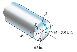
The steel rod having a diameter of 1 in. is subjected to an internal moment of M = 300lb•ft. Determine the stress created at points A and B. Also, sketch a three-dimensional view of the stress distribution acting over the cross section. 45 A B M = 300 lb-ft 0.5 in.
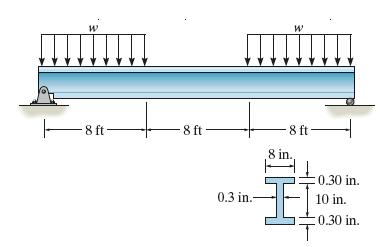
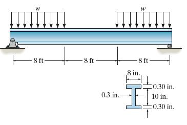
The steel beam has the cross sectional area shown. Determine the largest intensity of distributed load w that it can support so that the bending stress does not exceed σmax = 22 ksi. 8 ft- 8 ft W -8 ft. 8 in., 0.30 in. 0.3 in.- 10 in. 0.30 in.
The steel beam has the cross-sectional area shown. If w=5 kip/ft, determine the absolute maximum bending stress in the beam. W 8 8 ft- 8 ft W ft- -8 ft- .8 in. 0.30 in. 0.3 in.- 10 in. 0.30 in.
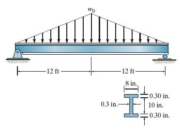
Determine the largest intensity of distributed load w0 that the beam can support so that the maximum bending stress in the beam does not exceed σmax = 22ksi. Wo -12 ft. 12 ft- 8 in. 0.30 in. 0.3 in.- 10 in. 0.30 in.
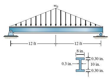
If w0 = 0.5 kip/ft, determine the maximum bending stress in the beam. Wo 12 ft. 12 ft- 8 in. 0.30 in. 0.3 in.- 10 in. 0.30 in.
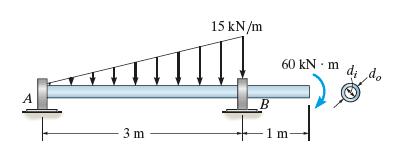
Determine the absolute maximum bending stress in the tubular shaft if di = 160 mm and do = 200 mm. A 15 kN/m 60 kNm 3 m 1 m- do
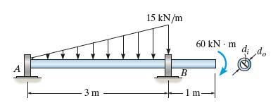
The tubular shaft is to have a cross section such that its inner diameter and outer diameter are related by di = 0.8do. Determine these required dimensions if the allowable bending stress is σallow = 155 MPa. A 3 m 15 kN/m 60 kN - m di do B 1 m-
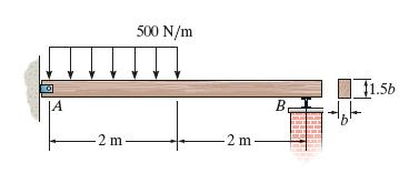
The wood beam has a rectangular cross section in the proportion shown. Determine its required dimension b if the allowable bending stress is σallow = 10 MPa. |A 500 N/m -2 m 2 m B 1.56
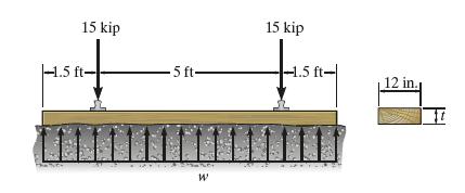
If the reaction of the ballast on the railway tie can be assumed uniformly distributed over cross section its length as shown, determine the maximum bending stress developed in the tie. The tie has the rectangular cross section with thickness t = 6 in. 15 kip .5 ft- 5 ft- W 15 kip -1.5 ft- 12 in.
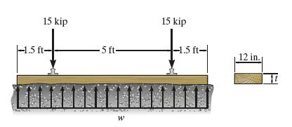
The reaction of the ballast on the railway tie can be assumed uniformly distributed over its length as shown. If the wood has an allowable bending stress of σallow = 1.5 ksi, determine the required minimum thickness t of the rectangular cross section area of the tie to the nearest 1/8 in. 15 kip
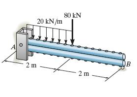
The two solid steel rods are bolted together along their length and support the loading shown. Assume the support at A is a pin and B is a roller. Determine the required diameter d of each of the rods if the allowable bending stress is σallow = 130MPa. A 20 kN/m 80 kN 2 m 2 m B
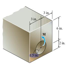
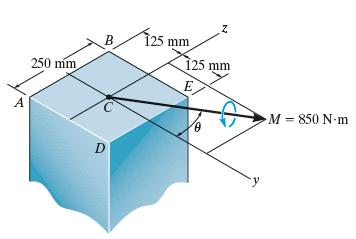
The member is subjected to the moment M = 850 N⋅m. Determine the stress at each corner and sketch the stress distribution. Set θ = 30. 250 mm D B 125 mm Z 125 mm E M = 850 N-m
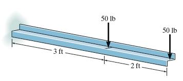
The cantilever beam is made from the Z section having the cross section shown. If it supports the two loadings, determine the bending stress at the wall in the beam at point B. Use the result of Prob. 6–106.Data from Prob. 6–106 50 lb 50 lb 3 ft 2 ft.
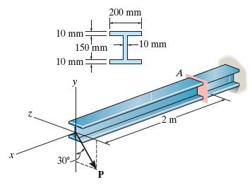
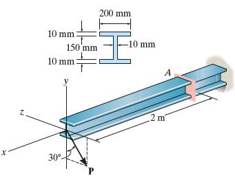
The cantilever wide-flange steel beam is subjected to the concentrated force P at its end. Determine the largest magnitude of this force so that the bending stress developed at A does not exceed σallow = 180MPa. 10 mm: 150 mm 10 mm: 200 mm IH x 30 P -10 mm 2 m A
The cantilever wide-flange steel beam is subjected to the concentrated force of P = 600N at its end. Determine the maximum bending stress developed in the beam at section A. Z 10 mm: 150 mm 10 mm: 200 mm IH x 30 P -10 mm A 2 m
A white spruce beam is reinforced with A-36 steel straps at its top and bottom as shown. Determine the bending moment M it can support if (σst) allow = 22 ksi and ( σw) allow = 2.0 ksi. 3 in. 4 in. 0.5 in. i M 0.5 in. x
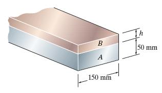
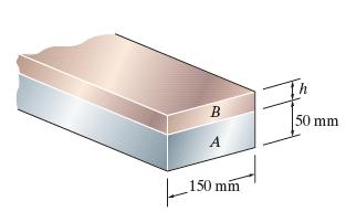
The composite beam is made of 6061-T6 aluminum (A) and C83400 red brass (B). Determine the dimension h of the brass strip so that the neutral axis of the beam is located at the seam of the two metals. What maximum moment will this beam support if the allowable bending stress for the aluminum is
The composite beam is made of 6061-T6 aluminum (A) and C83400 red brass (B). If the height h = 40 mm, determine the maximum moment that can be applied to the beam if the allowable bending stress for the aluminum is (σal) allow =128 MPa and for the brass ( σbr) allow = 35 MPa. B 50 mm |_ 150 A 150
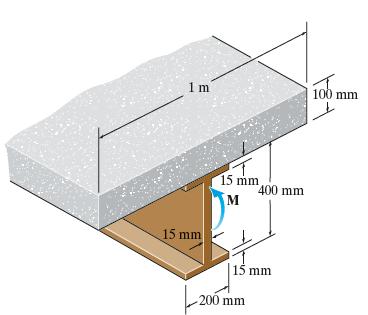
The low strength concrete floor slab is integrated with a wide-flange A-36 steel beam using shear studs (not shown) to form the composite beam. If the allowable bending stress for the concrete is (σcon) allow = 10 MPa, and allowable bending stress for steel is ( σst) allow = 165 MPa, determine
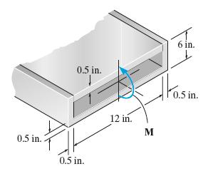
The top plate is made of 2014-T6 aluminum and is used to reinforce a Kevlar 49 plastic beam. Determine the maximum stress in the aluminum and in the Kevlar if the beam is subjected to a moment of M = 900 lb⋅ ft. 6 in. 0.5 in. 12 in. 10.5 0.5 in. 0.5 in. 0.5 in. M
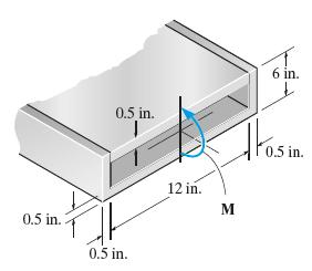
The top plate made of 2014-T6 aluminum is used to reinforce a Kevlar 49 plastic beam. If the allowable bending stress for the aluminum is (σallow) al = 40 ksi and for the Kevlar ( σallow)K = 8 ksi, determine the maximum moment M that can be applied to the beam. 0.5 in. 0.5 in. 0.5 in. 12 in. M 6
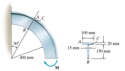
The curved beam is subjected to a bending moment of M=900 N⋅ m. Determine the stress at point C. 30 B 400 mm A C 15 mm 100 mm A. B M 20 mm 150 mm
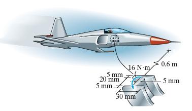
While in flight, the curved rib on the jet plane is subjected to an anticipated moment of M = 16N ⋅ m at the section. Determine the maximum bending stress in the rib at this section, and sketch a two-dimensional view of the stress distribution. 0.6 m 16 N-m 5 mm 20 mm 5 mm. -5 mm 30 mm
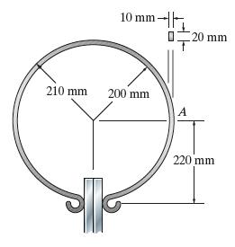
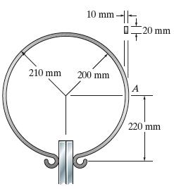
The circular spring clamp produces a compressive force of 3 N on the plates. Determine the maximum bending stress produced in the spring at A. The spring has a rectangular cross section as shown. 10 mm 210 mm 200 mm A 20 mm 220 mm
Determine the maximum compressive force the spring clamp can exert on the plates if the allowable bending stress for the clamp is σallow = 4MPa. The spring has a rectangular cross section as shown. 10 mm- [20 mm 20 210 mm 200 mm A 220 mm
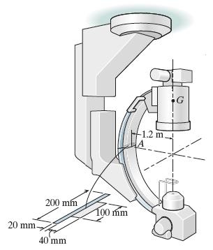
The ceiling-suspended C-arm is used to support the X-ray camera used for medical diagnoses. If the camera has a mass of 150 kg, with center of mass at G, determine the maximum bending stress at section A. 200 mm 20 mm. 40 mm 100 mm -1.2 m. A G
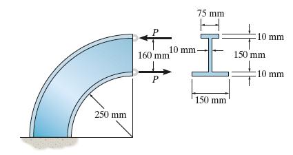
Determine the greatest magnitude of the applied forces P if the allowable bending stress is (σc)allow = 50 MPa in compression and (σt) allow =120 MPa in tension. 250 mm 75 mm 10 mm 10 mm- 150 mm 160 mm 10 mm P 150 mm
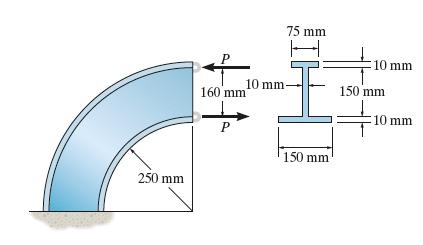
If P = 6kN, determine the maximum tensile and compressive bending stresses in the beam. 250 mm 75 mm 10 mm 10 mm- 150 mm 160 mm 10 mm P 150 mm
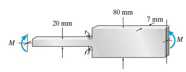
The bar is subjected to a moment M = 40 N⋅m of Determine the smallest radius r of the fillets so that an allowable bending stress of σallow = 124MPa is not exceeded. M 20 mm 80 mm 7 mm M
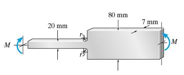
The bar is subjected to a moment of M = 17.5 N ⋅ m. If r=5mm determine the maximum bending stress in the material. M 80 mm 7 mm 20 mm M
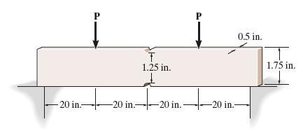
The simply supported notched bar is subjected to the two loads, each having a magnitude of P = 100 lb. Determine the maximum bending stress developed in the bar, and sketch the bending-stress distribution acting over the cross section at the center of the bar. Each notch has a radius of r = 0.125
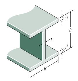
The wide-flange member is made from an elastic perfectly plastic material. Determine the shape factor for the beam. h
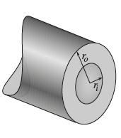
The beam is made from elastic perfectly plastic material. Determine the shape factor for the thick-walled tube.
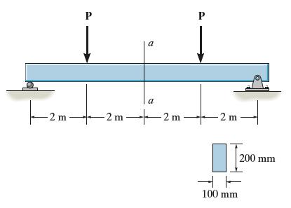
The beam is made of an elastic perfectly plastic material for which σy = 200 MPa. Determine the magnitude of each force P that causes the maximum internal moment to be moment to be(a) the maximum elastic moment and(b) the maximum plastic moment. -2 m P a a -2 m2m P [200 mm 100 mm
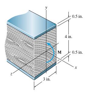
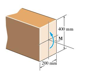
The beam has a rectangular cross section and is made of an elastic perfectly plastic material having a stress–strain diagram as shown. Determine the magnitude of the moment M that must be applied to the beam in order to create a maximum strain in its outer fibers of εmax = 0.008. 200 mm 400 mm M
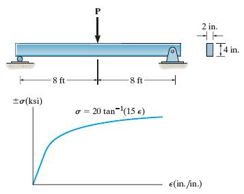
The beam is made of a polyester that has the stress-strain curve shown. If the curve can be represented by the equation σ = [20 tan-1 (15ε)] ksi where tan-1 (15ε) is in radians, determine the magnitude of the force P that can be applied to the beam without causing the maximum strain in its
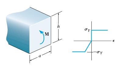
The beam is made of a material that can be assumed perfectly plastic in tension and elastic perfectly plastic in compression. Determine the maximum bending moment M that can be supported by the beam so that the compressive material at the outer edge starts to yield. M h E
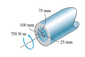
The tube is subjected to a torque of 750 N. m. Determine the amount of this torque that is resisted by the gray shaded section. Solve the problem two ways:(a) by using the torsion formula,(b) by finding the resultant of the shear stress distribution. 100 mm 750 Nm 75 mm 25 mm
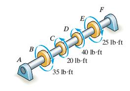
The solid shaft has a diameter of 0.75 in. If it is subjected to the torques shown, determine the maximum shear stress developed in regions BC and DE of the shaft. The bearings at A and F allow free rotation of the shaft. B A 40 lb ft 20 lb-ft 35 lb-ft 25 lb-ft
Showing 1000 - 1100
of 1529
First
2
3
4
5
6
7
8
9
10
11
12
13
14
15
16
Step by Step Answers