

Question: Design and implement in Verilog a 4-bit ALUusing gate-level modeling. It shouldtake two 4-bitinputs A and B ,and produce a 4-bit output Result byperforming 7
Design and implement in Verilog a 4-bit ALUusing gate-level modeling. It shouldtake two 4-bitinputs A and B,and produce a 4-bit output Result byperforming 7 different operations accordong to its 4-bit controlinput as defined in the following table.
| ALU control input | Operation |
| 0000 | Results = A & B (bitwise AND) |
| 0001 | Results = A | B (bitwise OR) |
| 0010 | Results = A + B (aritmetic ADD) |
| 0110 | Results = A - B (arithmetic SUB) |
| 0111 | Result = 1, if A |
| 1100 | Results = ~(A | B) (bitwise NOR) |
| 1101 | Results = ~(A & B) (bitwise NAND) |
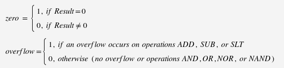
In addtion the ALU should have two other outputs- zero and overflow,defined as follows:
Design and imlement the ALU as described inlecture Designing an ALU. Use hierarchical design and createthree different modules: 1-bit ALU for bits 0-2, 1-bit ALU for bit3, and a 4-bit ALU that uses the instances of the first two.See ALU4-behavioral.vl for the inputs/outputs andfunctionality of your ALU. It should work exactly in the same wayas ALU4-behavioral.vl and may be tested with the sametest module, however should be implemented entirely atgate-level.
Documentation andsubmission: Submit a single report file (MSWord, PDF) as an attachment to this assignment. The report shouldinclude:
- Descriptive text (ALU operations, operation codes, inputsand outputs)
- Logic diagrams for each module (1-bit ALU for bits 0-2,1-bit ALU for bit 3, and 4-bit ALU). Use block-level diagrams forthe adders and multiplexers. In the logic diagrams label eachmodule I/O with the variable name used in the Verilog code.
- Verilog source code of all modules including the testmodule.
- Simulation results (output from running the compiled Verilogcode with the test module). The simulation should show theperformance of the ALU for all 7 operations (AND, OR,ADD, SUB, SLT, NOR, NAND). For this purpose include a copy ofthe test module output showing a few typicalexamples for each operation, including Overflow and Zero.Label the columns for the inputs and outputs and print the datainputs and outputs inboth binary and signed decimal format. Youmay use the test module from ALU4-behavioral.vl.
Extra credit (maximum 20% of the projectgrade): Implement two additional functions:Arithmetic shift right by 1 bit, and Rotate left by 1 bit.These operations should apply to one of the ALU inputs (a). Includea text description, a logic diagram and test results.
zero = 1, if Result=0 0, if Result #0 overflow= 1, if an overflow occurs on operations ADD, SUB, or SLT 0, otherwise (no overflow or operations AND, OR, NOR, or NAND)
Step by Step Solution
3.50 Rating (157 Votes )
There are 3 Steps involved in it
Hence is your answer Solution is given below Verilog code module HA absumcarry input ab ou... View full answer

Get step-by-step solutions from verified subject matter experts