

Question: Using MPLAB - ADC _ Controlled _ Pulse Description: - This program reads the Analog voltage from the potentiometer on input AN 0 (
Using MPLAB ADCControlledPulse
Description: This program reads the Analog voltage from the potentiometer on input ANRA as a bit value and turns ON the LED connected to pin RB with an ontime proportional to the ADC value using a For Loop. As you adjust the potentiometer ie ADC value this will vary the ON Vs OFF time of the LED which is used to implement a variable brightness on the LED. This is effectively a PWM Pulse Width Modulated waveform.
Instructions:
Create a macro name for the LED:
Eg#define LED RB
Create a macro name for ON and OFF :
Eg#define ON
#define OFF
Use the macros listed above in your program.
Setup RB pin as a Digital Output.
Setup ANRA pin as an Analog input.
Setup the ADC as follows see ADCON& ADCON registers on pages of the PICF Datasheet:
ADCON
Setup "ADCS : bits to select the internal RC oscillator
Setup CHS: to select Channel ie RAAN
Setup "ADON" bit to turn on AD module
ADCON
Setup "ADFM" bit to select Right Justified result
Setup "ADCS bit as disabled
Setup VCFG : bits to use AVDD and AVss
Create a bit variable called "adcval", to store the bit adc result.
Inside a continuous loop, start an A barD C conversion by writing to the GODONE" bit.
Wait until the ADC conversion has completed.
Align the bit adc value from ADRESL & ADSREH inside the variable "adcval".
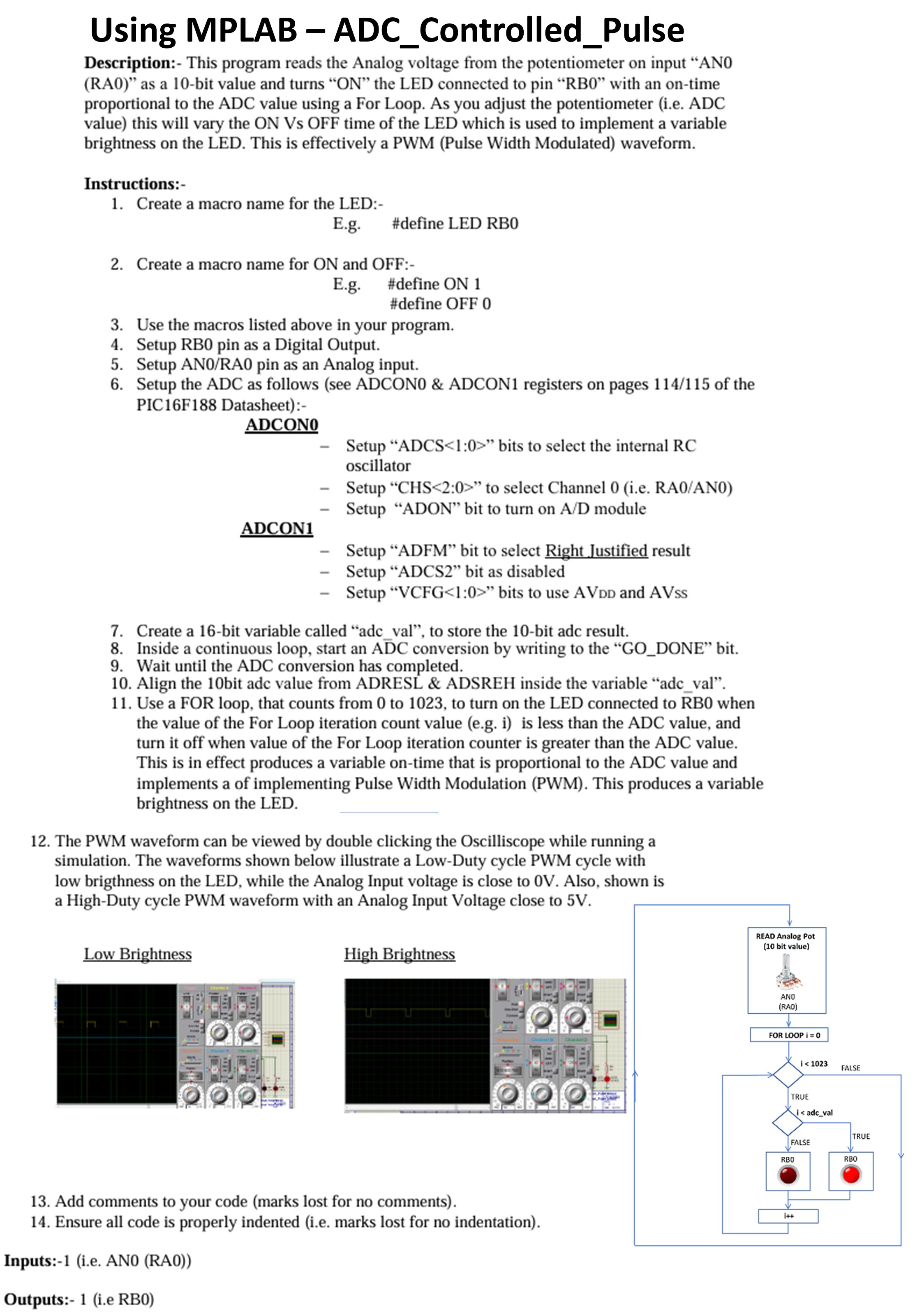
Use a FOR loop, that counts from to to turn on the LED connected to RB when the value of the For Loop iteration count value eg i is less than the ADC value, and turn it off when value of the For Loop iteration counter is greater than the ADC value. This is in effect produces a variable ontime that is proportional to the ADC value and implements a of implementing Pulse Width Modulation PWM This produces a variable brightness on the LED.
The PWM waveform can be viewed by double clicking the Oscilliscope while running a simulation. The waveforms shown below illustrate a LowDuty cycle PWM cycle with low brigthness on the LED, while the Analog Input voltage is close to V Also, shown is a HighDuty cycle PWM waveform with an Analog Input Voltage close to V
Add comments to your code marks lost for no comments
Ensure all code is properly indented ie marks lost for no indentation
Inputs:ie ANRA
Outputs:ie RB
Step by Step Solution
There are 3 Steps involved in it
1 Expert Approved Answer
Step: 1 Unlock

Question Has Been Solved by an Expert!
Get step-by-step solutions from verified subject matter experts
Step: 2 Unlock
Step: 3 Unlock