New Semester
Started
Get
50% OFF
Study Help!
--h --m --s
Claim Now
Question Answers
Textbooks
Find textbooks, questions and answers
Oops, something went wrong!
Change your search query and then try again
S
Books
FREE
Study Help
Expert Questions
Accounting
General Management
Mathematics
Finance
Organizational Behaviour
Law
Physics
Operating System
Management Leadership
Sociology
Programming
Marketing
Database
Computer Network
Economics
Textbooks Solutions
Accounting
Managerial Accounting
Management Leadership
Cost Accounting
Statistics
Business Law
Corporate Finance
Finance
Economics
Auditing
Tutors
Online Tutors
Find a Tutor
Hire a Tutor
Become a Tutor
AI Tutor
AI Study Planner
NEW
Sell Books
Search
Search
Sign In
Register
study help
sciences
digital systems design
Digital Systems Design Using Verilog 1st edition Charles Roth, Lizy K. John, Byeong Kil Lee - Solutions
A D flip-flop has a propagation delay from clock to Q of 15 ns. The setup time of the flip-flop is 10 ns, and the hold time is 2 ns. A clock with a period of 50 ns (low until 25 ns, high from 25 to 50 ns, and so on) is fed to the clock input of the flip-flop. The flip-flop is positive edge
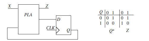
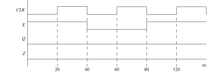
A sequential circuit consists of a PLA and a D flip-flop, as shown in the following diagram.(a) Complete the timing diagram assuming that the propagation delay for the PLA is in the range 5 to 10 ns and the propagation delay from clock to output of the D flip-flop is 5 to 10 ns. Use cross-hatching
A D flip-flop has a propagation delay from clock to Q of 7 ns. The setup time of the flip-flop is 10 ns, and the hold time is 5 ns. A clock with a period of 50 ns (low until 25 ns, high from 25 to 50 ns, and so on) is fed to the clock input of the flip-flop. Assume a 2-level AND-OR circuitry
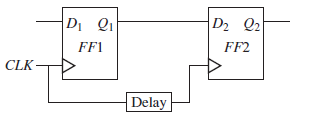
Two flip-flops are connected as shown in the following diagram. The delay represents wiring delay between the two clock inputs, which results in clock skew. This can cause possible loss of synchronization. The flip-flop propagation delay from clock to Q is 10 ns < tp< 15 ns, and the setup and
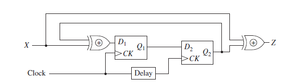
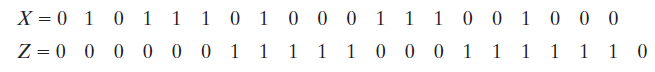
A Mealy sequential circuit is implemented using the circuit shown in Problem 1.26. Assume that if the input X changes, it changes at the same time as the falling edge of the clock.(a) Complete the timing diagram shown here. Indicate the proper times to read the output (Z). Assume that
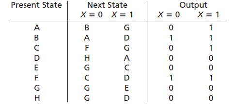
Reduce the following state table to a minimum number of states. Present State Next State Output X = 1 X = 0 X= 1 B A D н D G Н D
Derive the state transition table and D flip-flop input equations for a counter that counts from 1 to 6 (and back to 1 and continues).
Derive the state transition table and flip-flop input equations for a modulo-6 counter that counts 000 through 101 and then repeats. Use J-K flip-flops.
A Moore sequential circuit has one input and one output. The output goes to 1 when the input sequence 111 has occurred, and the output goes to 0 if the input sequence 000 occurs. At all other times, the output holds its value. For example, Derive a Moore state graph and table for the circuit.
A sequential circuit has one input (X) and two outputs (D and B). X represents a 4-bit binary number N, which is input least significant bit first. D represents a 4-bit binary number equal to N – 2, which is output least significant bit first. At the time the fourth input occurs, B = 1 if N - 2
A sequential circuit has one input (X) and two outputs (S and V). X represents a 4-bit binary number N, which is input least significant bit first. S represents a 4-bit binary number equal to N + 2, which is output least significant bit first. At the time the fourth input occurs, V = 1 if N + 2 is
A sequential circuit has one input (X) and two outputs (Z1 and Z2). An output Z1 = 1 occurs every time the input sequence 010 is completed provided that the sequence100 has never occurred. An output Z2 = 1 occurs every time the input sequence 100 is completed. Once a Z2 = 1 output has occurred, Z1
A synchronous sequential circuit has one input and one output. If the input sequence 0101 or 0110 occurs, an output of two successive 1s will occur. The first of these 1s should occur coincident with the last input of the 0101 or 0110 sequence. The circuit should reset when the second 1 output
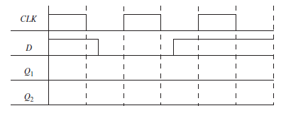
Construct a clocked D flip-flop, triggered on the rising edge of CLK, using two transparent D latches and any necessary gates. Complete the following timing diagram, where Q1and Q2are latch outputs. Verify that the flip-flop output changes to D after the rising edge of the clock. CLK
(a) Show how you can construct a T flip-flop using a J-K flip-flop.(b) Show how you can construct a J-K flip-flop using a D flip-flop and gates.
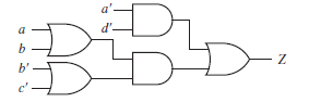
(a) Find all the static hazards in the following circuit. State the condition under which each hazard can occur.(b) Redesign the circuit so that it is free of static hazards. Use gates with at most three inputs. a'. b' c'
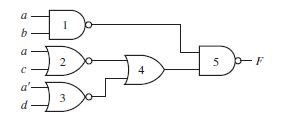
(a) Find all the static hazards in the following circuit. For each hazard, specify the values of the input variables and which variable is changing when the hazard occurs.For one of the hazards, specify the order in which the gate outputs must change.(b) Design a NAND-gate circuit that is free of
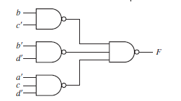
Find all of the 1-hazards in the given circuit. Indicate which changes are necessary to eliminate the hazards. c'
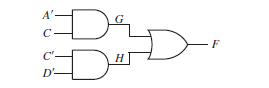
Identify the static 1-hazards in the following circuit. State the condition under which each hazard can occur. Draw a timing diagram (similar to Figure 1-10(b)) that shows the sequence of events when a hazard occurs. A' -F
For the following functions, find the minimum sum of products using 4-variable maps with map-entered variables. In (a) and (b), mi represents a minterm of variablesA, B, C, and D.(a) F(A, B, C, D, E) = ∑m(0, 4, 6, 13, 14) + ∑d(2, 9) + E(m1 + m12)(b) Z(A, B, C, D, E, F, G) = ∑m(2, 5, 6, 9) +
Simplify Z using a 4-variable map with map-entered variables. ABCD represents the state of a control circuit. Assume that the circuit can never be in state 0100, 0001, or 1001. Z = BC'DE + ACDF' + ABCD'F' + ABC'D'G + B'CD + ABC'D'H'
A full subtracter computes the difference of three inputs X, Y, and Bin, where Diff = X - Y - Bin. When X < (Y + Bin), the borrow output Bout is set. Fill in the truth table for the subtracter and derive the sum-of-products and product-of-sums equations for Diff and Bout.
Write out the truth table for the following equation:F = (A ⊕ B) ∙ + A' ∙ (B' ⊕ C)
Showing 300 - 400
of 323
1
2
3
4
Step by Step Answers