New Semester
Started
Get
50% OFF
Study Help!
--h --m --s
Claim Now
Question Answers
Textbooks
Find textbooks, questions and answers
Oops, something went wrong!
Change your search query and then try again
S
Books
FREE
Study Help
Expert Questions
Accounting
General Management
Mathematics
Finance
Organizational Behaviour
Law
Physics
Operating System
Management Leadership
Sociology
Programming
Marketing
Database
Computer Network
Economics
Textbooks Solutions
Accounting
Managerial Accounting
Management Leadership
Cost Accounting
Statistics
Business Law
Corporate Finance
Finance
Economics
Auditing
Tutors
Online Tutors
Find a Tutor
Hire a Tutor
Become a Tutor
AI Tutor
AI Study Planner
NEW
Sell Books
Search
Search
Sign In
Register
study help
sciences
mechanics of materials
Mechanics Of Materials 10th Edition Russell C. Hibbeler - Solutions
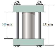
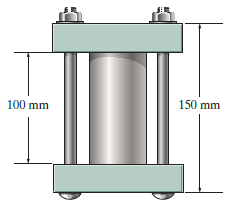
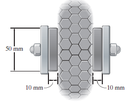
The 50-mm-diameter cylinder is made from Am 1004-T61 magnesium and is placed in the clamp when the temperature is T1= 20° C. If the 304-stainless-steel carriage bolts of the clamp each have a diameter of 10 mm, and they hold the cylinder snug with negligible force against the rigid jaws,
The 50-mm-diameter cylinder is made from Am 1004-T61 magnesium and is placed in the clamp when the temperature is T1= 15°C. If the two 304-stainless-steel carriage bolts of the clamp each have a diameter of 10 mm, and they hold the cylinder snug with negligible force against the rigid jaws,
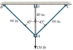
The wires AB and AC are made of steel, and wire AD is made of copper. Before the 150-lb force is applied, AB and AC are each 60 in. long and AD is 40 in. long. If the temperature is increased by 80€‘F, determine the force in each wire needed to support the load. Each wire has a
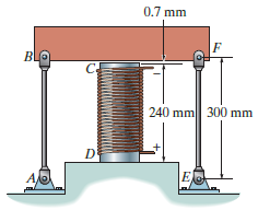
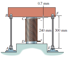
The cylinder CD of the assembly is heated from T1= 30°C to T2= 180°C using electrical resistance. At the lower temperature T1the gap between C and the rigid bar is 0.7 mm. Determine the force in rods AB and EF caused by the increase in temperature. Rods AB and EF are made of steel, and each
The cylinder CD of the assembly is heated from T1= 30°C to T2= 180°C using electrical resistance. Also, the two end rods AB and EF are heated from T1= 30°C to T2= 50°C. At the lower temperature T1 the gap between C and the rigid bar is 0.7 mm. Determine the force in rods AB and EF
The metal strap has a thickness t and width w and is subjected to a temperature gradient T1 to T2 (T1 < T2). This causes the modulus of elasticity for the material to vary linearly from E1 at the top to a smaller amount E2 at the bottom. As a result, for any vertical position y, measured from
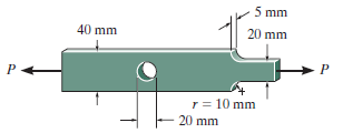
Determine the maximum normal stress developed in the bar when it is subjected to a tension of P = 8 kN. 5 mm 40 mm 20 mm r = 10 mm 20 mm
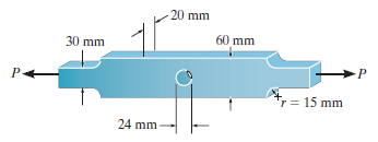
The steel bar has the dimensions shown. Determine the maximum axial force P that can be applied so as not to exceed an allowable tensile stress of σallow= 150 MPa. 20 mm 60 mm 30 mm r = 15 mm 24 mm
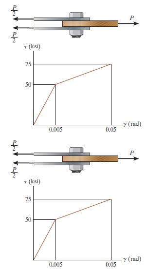
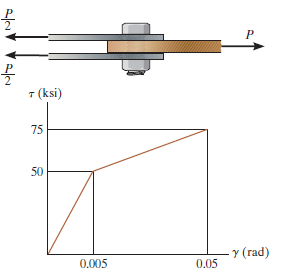
The lap joint is connected together using a 1.25 in. diameter bolt. If the bolt is made from a material having a shear stress€“strain diagram that is approximated as shown, determine the permanent shear strain in the shear plane of the bolt when the applied force P = 150 kip is removed. T (ksi)
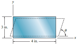
The rubber block is subjected to an elongation of 0.03 in. along the x axis, and its vertical faces are given a tilt so that θ = 89.3°. Determine the strains εx, εyand γxy. Take vr= 0.5. y 3 in. 4 in.
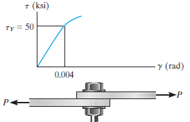
The shear stress€“strain diagram for an alloy is shown in the figure. If a bolt having a diameter of 0.25 in. is made of this material and used in the lap joint, determine the modulus of elasticity E and the force P required to cause the material to yield. Take v = 0.3. 7 (ksi) Ty = 50 Y
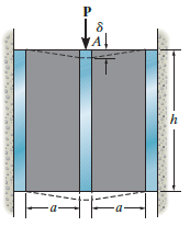
A shear spring is made from two blocks of rubber, each having a height h, width b, and thickness a. The blocks are bonded to three plates as shown. If the plates are rigid and the shear modulus of the rubber is G, determine the displacement of plate A when the vertical load P is applied. Assume
The elastic portion of the tension stress€“strain diagram for an aluminum alloy is shown in the figure. The specimen used for the test has a gage length of 2 in. and a diameter of 0.5 in. When the applied load is 9 kip, the new diameter of the specimen is 0.49935 in. Calculate the shear
The elastic portion of the tension stress€“strain diagram for an aluminum alloy is shown in the figure. The specimen used for the test has a gage length of 2 in. and a diameter of 0.5 in. If the applied load is 10 kip, determine the new diameter of the specimen. The shear modulus is Gal=
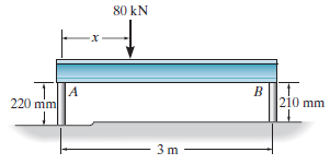
The rigid beam rests in the horizontal position on two 2014-T6 aluminum cylinders having the unloaded lengths shown. If each cylinder has a diameter of 30 mm, determine the placement x of the applied 80-kN load so that the beam remains horizontal. What is the new diameter of cylinder A after the
The lap joint is connected together using a 1.25 in. diameter bolt. If the bolt is made from a material having a shear stress€“strain diagram that is approximated as shown, determine the permanent shear strain in the shear plane of the bolt when the applied force P = 150 kip is removed. T
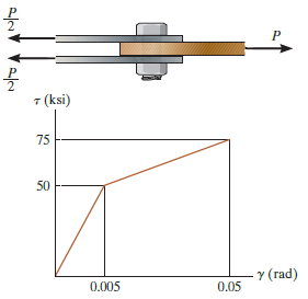
The lap joint is connected together using a 1.25 in. diameter bolt. If the bolt is made from a material having a shear stress€“strain diagram that is approximated as shown, determine the shear strain developed in the shear plane of the bolt when P = 75 kip. 7 (ksi) 75 50 Y (rad) 0.005 0.05
The brake pads for a bicycle tire are made of rubber. If a frictional force of 50 N is applied to each side of the tires, determine the average shear strain in the rubber. Each pad has cross-sectional dimensions of 20 mm and 50 mm. Gr= 0.20 MPa. 50 mm 10 mm 10 mm
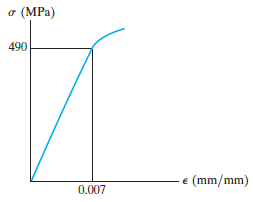
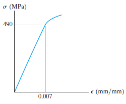
The elastic portion of the stress€“strain diagram for an aluminum alloy is shown in the figure. The specimen from which it was obtained has an original diameter of 12.7 mm and a gage length of 50.8 mm. If a load of P = 60 kN is applied to the specimen, determine its new diameter and
The elastic portion of the stress€“strain diagram for an aluminum alloy is shown in the figure. The specimen from which it was obtained has an original diameter of 12.7 mm and a gage length of 50.8 mm. When the applied load on the specimen is 50 kN, the diameter is 12.67494 mm. Determine
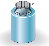
The plug has a diameter of 30 mm and fits within a rigid sleeve having an inner diameter of 32 mm. Both the plug and the sleeve are 50 mm long. Determine the axial pressure p that must be applied to the top of the plug to cause it to contact the sides of the sleeve. Also, how far must the plug be
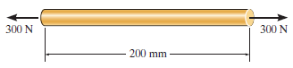
The acrylic plastic rod is 200 mm long and 15 mm in diameter. If an axial load of 300 N is applied to it, determine the change in its length and the change in its diameter. Ep= 2.70 GPa, vp= 0.4. 300 N 300 N 200 mm
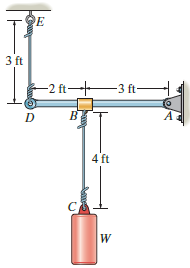
The bar DA is rigid and is originally held in the horizontal position when the weight W is supported from C. If the weight causes B to displace downward 0.025 in., determine the strain in wires DE and BC. Also, if the wires are made of A-36 steel and have a cross-sectional area of 0.002 in2,
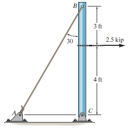
The pole is supported by a pin at C and an A-36 steel guy wire AB. If the wire has a diameter of 0.2 in., determine how much it stretches when a horizontal force of 2.5 kip acts on the pole. 3 ft 2.5 kip 30 4 ft
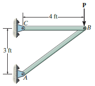
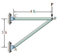
The two bars are made of a material that has the stress€“strain diagram shown. Determine the cross-sectional area of each bar so that the bars fracture simultaneously when the load P = 3 kip. Assume that buckling does not occur. -4 ft- lc ов 3'ft
The two bars are made of a material that has the stress€“strain diagram shown. If the cross-sectional area of bar AB is 1.5 in2and BC is 4 in2, determine the largest force P that can be supported before any member fractures. Assume that buckling does not occur. -4 ft- OB 3'ft
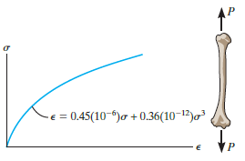
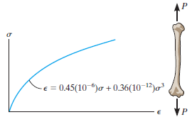
The stress€“strain diagram for a bone is shown and can be described by the equation ε = 0.45(10€“6) σ + 0.36(10€“12) σ3, where σ is in kPa. Determine the modulus of toughness and the amount of elongation of a 200-mm-long
The stress€“strain diagram for a bone is shown, and can be described by the equation ε = 0.45(10€“6) σ + 0.36(10€“12) σ3, where s is in kPa. Determine the yield strength assuming a 0.3% offset. = 0.45(10-)o + 0.36(10-12)o
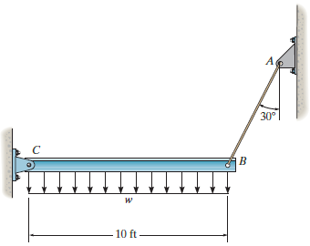
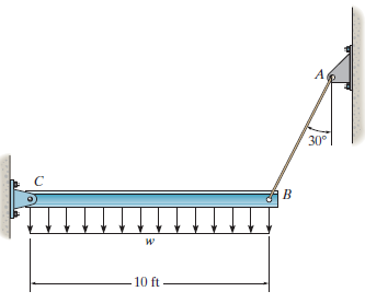
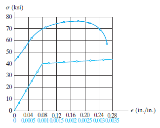
The rigid beam is supported by a pin at C and an A992 steel guy wire AB of length 6 ft. If the wire has a diameter of 0.2 in., determine the distributed load w if the end B is displaced 0.12 in. downward. The wire remains elastic. A, 30° 10 ft
The rigid beam is supported by a pin at C and an A992 steel guy wire AB of length 6 ft. If the wire has a diameter of 0.2 in., determine how much it stretches when a distributed load of w = 200 lb/ft acts on the beam. The wire remains elastic. 30° 10 ft
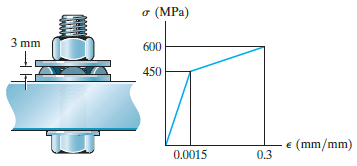
Direct tension indicators are sometimes used instead of torque wrenches to ensure that a bolt has a prescribed tension when used for connections. If a nut on the bolt is tightened so that the six 3-mm high heads of the indicator are strained 0.1 mm/mm, and leave a contact area on each head of 1.5
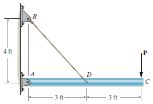
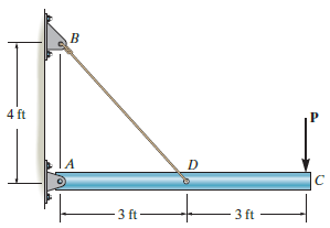
The rigid pipe is supported by a pin at A and an A-36 guy wire BD. If the wire has a diameter of 0.25 in., determine the load P if the end C is displaced 0.075 in. downward. 4 ft 3 ft 3 ft
The rigid pipe is supported by a pin at A and an A-36 steel guy wire BD. If the wire has a diameter of 0.25 in., determine how much it stretches when a load of P = 600 lb acts on the pipe. 4 ft 3 ft 3 ft
A bar having a length of 5 in. and cross-sectional area of 0.7 in.2is subjected to an axial force of 8000 lb. If the bar stretches 0.002 in., determine the modulus of elasticity of the material. The material has linear elastic behavior. 8000 Ib 8000 lb 5 in.-
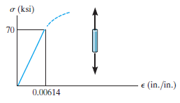
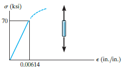
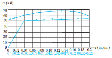
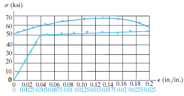
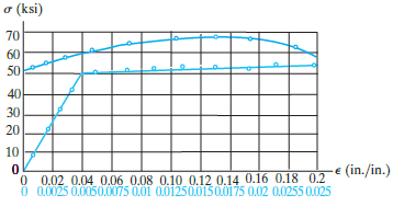
The stress€“strain diagram for an aluminum alloy specimen having an original diameter of 0.5 in. and a gage length of 2 in. is given in the figure. Determine approximately the modulus of resilience and the modulus of toughness for the material. o (ksi) 70 60 50 40 30 20 10 -e (in./in.) 0
The stress€“strain diagram for an aluminum alloy specimen having an original diameter of 0.5 in. and a gage length of 2 in. is given in the figure. If the specimen is loaded until it is stressed to 60 ksi, determine the approximate amount of elastic recovery and the increase in the gage
The stress€“strain diagram for an aluminum alloy specimen having an original diameter of 0.5 in. and a gage length of 2 in. is given in the figure. Determine approximately the modulus of elasticity for the material, the load on the specimen that causes yielding, and the ultimate load the
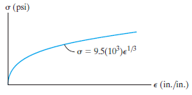
Acetal plastic has a stress€“strain diagram as shown. If a bar of this material has a length of 3 ft and cross-sectional area of 0.875 in2, and is subjected to an axial load of 2.5 kip, determine its elongation. o (psi) - a = 9.5(10³)e' e (in./in.)
The rigid beam is supported by a pin at C and an A-36 steel guy wire AB. If the wire has a diameter of 0.2 in., determine the distributed load w if the end B is displaced 0.75 in. downward. 30° 10 ft
The rigid beam is supported by a pin at C and an A-36 steel guy wire AB. If the wire has a diameter of 0.2 in., determine how much it stretches when a distributed load of w = 100 lb/ft acts on the beam. The material remains elastic. 30° -10 ft
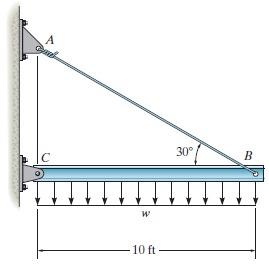
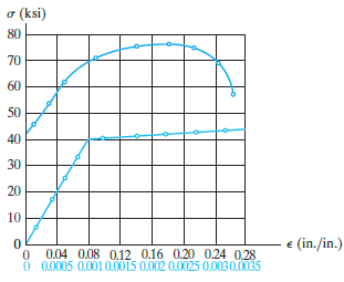
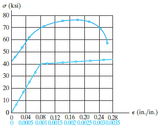
The stress€“strain diagram for a steel alloy having an original diameter of 0.5 in. and a gage length of 2 in. is given in the figure. Determine approximately the modulus of resilience and the modulus of toughness for the material. o (ksi) 80 70 60 50 40 30 20 10 e (in./in.) 0.04 0.08
The stress€“strain diagram for a steel alloy having an original diameter of 0.5 in. and a gage length of 2 in. is given in the figure. If the specimen is loaded until it is stressed to 70 ksi, determine the approximate amount of elastic recovery and the increase in the gage length after
The stress€“strain diagram for a steel alloy having an original diameter of 0.5 in. and a gage length of 2 in. is given in the figure. Determine approximately the modulus of elasticity for the material, the load on the specimen that causes yielding, and the ultimate load the specimen will
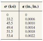
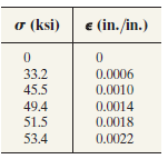
Data taken from a stress€“strain test for a ceramic are given in the table. The curve is linear between the origin and the first point. Plot the diagram, and determine approximately the modulus of toughness. The fracture stress is σf= 53.4 ksi. e (in. /in.) o (ksi) 33.2 0.0006
Data taken from a stress€“strain test for a ceramic are given in the table. The curve is linear between the origin and the first point. Plot the diagram, and determine the modulus of elasticity and the modulus of resilience. o (ksi) € (in./in.) 33.2 0.0006 45.5 0.0010 49.4 0.0014 51.5
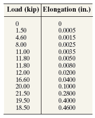
A tension test was performed on a steel specimen having an original diameter of 0.503 in. and gage length of 2.00 in. The data is listed in the table. Plot the stress€“strain diagram and determine approximately the modulus of elasticity, the yield stress, the ultimate stress, and the
If the normal strain is defined in reference to the final length Δs' that is,instead of in reference to the original length, Eq. 2€“2, show that the difference in these strains is represented as a second-order term, namely, ε €“ ε' =
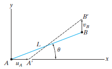
The fiber AB has a length L and orientation θ. If its ends A and B undergo very small displacements uAand vBrespectively, determine the normal strain in the fiber when it is in position A'B' B' в в -х А ил А'
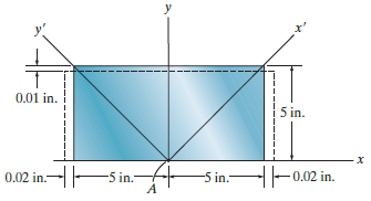
The rectangular plate undergoes a deformation shown by the dashed lines. Determine the shear strain γxyand γx'y'at point A. y 0.01 in. 5 in. 0.02 in.-ES in.- -|-0.02 in. -5 in.-
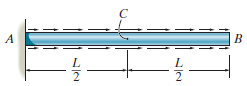
The nonuniform loading causes a normal strain in the shaft that can be expressed as εx= k sin (π/L x), where k is a constant. Determine the displacement of the center C and the average normal strain in the entire rod. A B L L
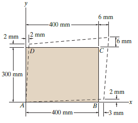
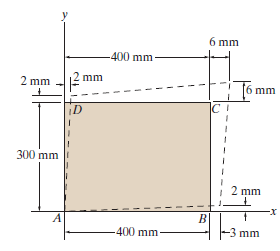
The rectangular plate is deformed into the shape shown by the dashed lines. Determine the average normal strain along diagonal BD, and the average shear strain at corner B relative to the x, y axes. 6 mm 400 mm 2 mm 2 mm 6 mm |C I 300 mm 2 mm x- B. -3 mm 400 mm
The rectangular plate is deformed into the shape shown by the dashed lines. Determine the average normal strain along diagonal AC, and the average shear strain at corner A relative to the x, y axes. 6 mm -400 mm- mm 2 mm mm ID 300 mm 2 mm x- B. -3 mm -400 mm-
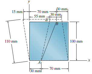
The block is deformed into the position shown by the dashed lines. Determine the average normal strain along line AB. 30 mm 30 mm 70 mm 15 mm 55 mm --B': 100 mm 110 mm 70 mm 130 mml
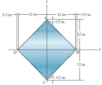
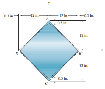
The corners of the square plate are given the displacements indicated. Determine the average normal strains along side AB and diagonals AC and BD. -12 in: -0.3 in. 0.3 in.- 12 in:- 0.5 in. 12 in. B' 12 in. 0.5 in.
The corners of the square plate are given the displacements indicated. Determine the shear strain at A relative to axes that are directed along AB and AD, and the shear strain at B relative to axes that are directed along BC and BA. -12 in.- 12 in:- -0.3 in. 0.3 in.- 0.5 in. 12 in. B' 12 in. 0.5 in.
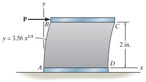
The polysulfone block is glued at its top and bottom to the rigid plates. If a tangential force, applied to the top plate, causes the material to deform so that its sides are described by the equation y = 3.56 x1/4, determine the shear strain at the corners A and B. B y = 3.56 x4. 2 in.
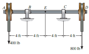
The shaft is supported by a smooth thrust bearing at B and a journal bearing at C. Determine the resultant internal loadings acting on the cross section at E. - 4 ft 4 ft +4 ft- 4 ft- 400 lb 800 lb
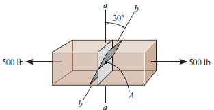
Determine the resultant internal normal and shear force in the member at (a) section a€“a and (b) section b€“b, each of which passes through the centroid A. The 500-lb load is applied along the centroidal axis of the member. 30° 500 Ib 500 lb
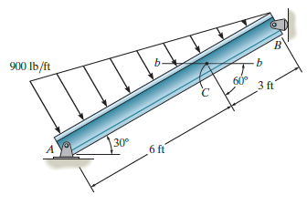
Determine the resultant internal loadings acting on section b€“b through the centroid C on the beam. B' 900 Ib/ft 60° 3 ft 30° A 6 ft
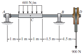
The shaft is supported by a smooth thrust bearing at A and a smooth journal bearing at B. Determine the resultant internal loadings acting on the cross section at C. 600 N/m -1 m--1 m---1 m--1.5 m-H.5 m- 900 N
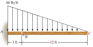
Determine the resultant internal loadings acting on the cross section at point B. 60 lb/ft 12 ft F3 ft-
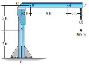
The boom DF of the jib crane and the column DE have a uniform weight of 50 lb/ft. If the supported load is 300 lb, determine the resultant internal loadings in the crane on cross sections at points A, B, and C. D :B Нa 3 ft- -8 ft 5 ft 300 lb 7 ft
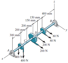
The shaft is supported at its ends by two bearings A and B and is subjected to the forces applied to the pulleys fixed to the shaft. Determine the resultant internal loadings acting on the cross section at point C. The 400-N forces act in the €“z direction and the 200-N and 80-N forces
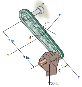
The hand crank that is used in a press has the dimensions shown. Determine the resultant internal loadings acting on the cross section at point A if a vertical force of 50 lb is applied to the handle as shown. Assume the crank is fixed to the shaft at B. 30° 4. 7 in. 7 in. 3 in. 50 lb
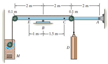
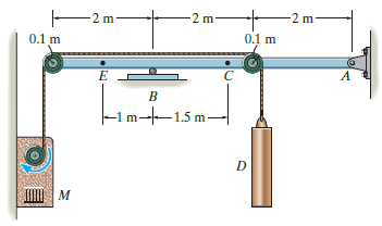
Determine the resultant internal loadings acting on the cross section at point C in the beam. The load D has a mass of 300 kg and is being hoisted by the motor M with constant velocity. 2 m- E2 m- -2 m 0.1 m 0.1 m A –-1 m-|–1.5 m- м
Determine the resultant internal loadings acting on the cross section at point E. The load D has a mass of 300 kg and is being hoisted by the motor M with constant velocity. -2 m 2 m m 0.1 m 0.1 m A -1 m--1.5 m– м
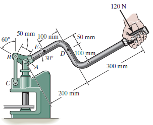
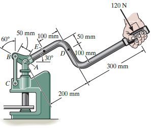
The metal stud punch is subjected to a force of 120 N on the handle. Determine the magnitude of the reactive force at the pin A and in the short link BC. Also, determine the resultant internal loadings acting on the cross section at point D. 120 N 50 mm 100 mm 50 mm 60 D 100 mm 30 300 mm 200 mm
Determine the resultant internal loadings acting on the cross section at point E of the handle arm, and on the cross section of the short link BC. 120 N 50 mm 60° 100 mm 50 mm 100 mm 30 300 mm mm 200
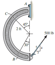
Determine the resultant internal loadings acting on the cross section at points B and C of the curved member. A 45 2 ft 500 lb 30°
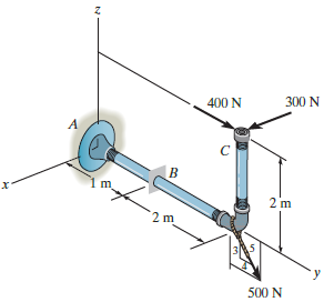
The pipe has a mass of 12 kg/m. If it is fixed to the wall at A, determine the resultant internal loadings acting on the cross section at B. 300 N 400 N m. 2 m 2 m 500 N
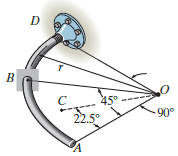
The curved rod AD of radius r has a weight per length of w. If it lies in the horizontal plane, determine the resultant internal loadings acting on the cross section at point B. 45° 90° 22.5°
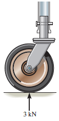
The supporting wheel on a scaffold is held in place on the leg using a 4-mm-diameter pin. If the wheel is subjected to a normal force of 3 kN, determine the average shear stress in the pin. Assume the pin only supports the vertical 3-kN load. 3 kN
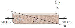
The board is subjected to a tensile force of 200 lb. Determine the average normal and average shear stress in the wood fibers, which are oriented along plane a€“a at 20° with the axis of the board. 2 in. a- 4 in. 20° 200 lb 200 Ib
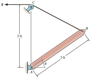
The boom has a uniform weight of 600 lb and is hoisted into position using the cable BC. If the cable has a diameter of 0.5 in., plot the average normal stress in the cable as a function of the boom position u for 0° ‰¤ θ ‰¤ 90°. 3 ft 3 ft
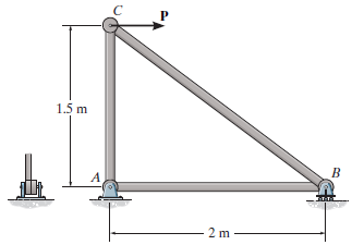
Determine the maximum average shear stress in pin A of the truss. A horizontal force of P = 40 kN is applied to joint C. Each pin has a diameter of 25 mm and is subjected to double shear. 1.5 m A 2 m
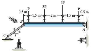
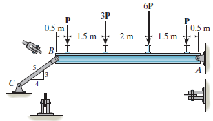
If P = 5 kN, determine the average shear stress in the pins at A, B, and C. All pins are in double shear, and each has a diameter of 18 mm. 6P ЗР 05 m 0.5 m -1.5 m -1.5 m - 2 m- в! I. A
Determine the maximum magnitude P of the loads the beam can support if the average shear stress in each pin is not to exceed 80 MPa. All pins are in double shear, and each has a diameter of 18 mm. 6P ЗР P. 0.5 m 0.5 m -1.5 m -1.5 m- 2 m- B, A
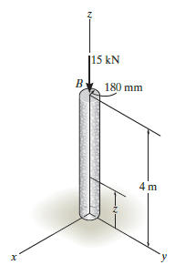
The column is made of concrete having a density of 2.30 Mg/m3. At its top B it is subjected to an axial compressive force of 15 kN. Determine the average normal stress in the column as a function of the distance z measured from its base. |15 kN 180 mm 4 m N-
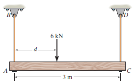
The beam is supported by two rods AB and CD that have cross-sectional areas of 12 mm2and 8 mm2, respectively. If d = 1 m, determine the average normal stress in each rod. ВФ ID 6 kN 3 m -
The beam is supported by two rods AB and CD that have cross-sectional areas of 12 mm2and 8 mm2, respectively. Determine the position d of the 6-kN load so that the average normal stress in each rod is the same. ID 6 kN A 3 m
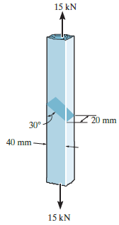
The two steel members are joined together using a 30° scarf weld. Determine the average normal and average shear stress resisted in the plane of the weld. 15 kN 20 mm 30° 40 mm 15 kN
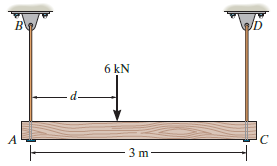
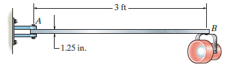
The railcar docklight is supported by the 1/8-in.-diameter pin at A. If the lamp weighs 4 lb, and the extension arm AB has a weight of 0.5 lb/ft, determine the average shear stress in the pin needed to support the lamp. 3 ft- IA -1.25 in.
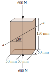
The plastic block is subjected to an axial compressive force of 600 N. Assuming that the caps at the top and bottom distribute the load uniformly throughout the block, determine the average normal and average shear stress acting along section a€“a. 600 N 150 mm 30 50 mm 50 mm 50 mm 600 N
Showing 900 - 1000
of 983
1
2
3
4
5
6
7
8
9
10
Step by Step Answers