New Semester
Started
Get
50% OFF
Study Help!
--h --m --s
Claim Now
Question Answers
Textbooks
Find textbooks, questions and answers
Oops, something went wrong!
Change your search query and then try again
S
Books
FREE
Study Help
Expert Questions
Accounting
General Management
Mathematics
Finance
Organizational Behaviour
Law
Physics
Operating System
Management Leadership
Sociology
Programming
Marketing
Database
Computer Network
Economics
Textbooks Solutions
Accounting
Managerial Accounting
Management Leadership
Cost Accounting
Statistics
Business Law
Corporate Finance
Finance
Economics
Auditing
Tutors
Online Tutors
Find a Tutor
Hire a Tutor
Become a Tutor
AI Tutor
AI Study Planner
NEW
Sell Books
Search
Search
Sign In
Register
study help
sciences
mechanics of materials
Mechanics Of Materials 10th Edition Russell C. Hibbeler - Solutions
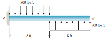
Draw the shear and moment diagrams for the beam. 800 Ib/ft 800 lb/ft 8 ft- 8 ft
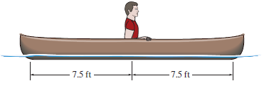
The 150-lb man sits in the center of the boat, which has a uniform width and a weight per linear foot of 3 lb/ft. Determine the maximum internal bending moment. Assume that the water exerts a uniform distributed load upward on the bottom of the boat. - 7.5 ft- - 7.5 ft-
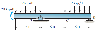
Draw the shear and moment diagrams for the beam. 2 kip/ft 2 kip/ft 20 kip-ft -5 ft- -5 ft-
Draw the shear and moment diagrams for the overhanging beam.
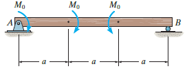
Draw the shear and moment diagrams for the beam. Mo Mo A
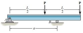
Determine the placement distance of the roller support so that the largest absolute value of the moment is a minimum. Draw the shear and moment diagrams for this condition. B.
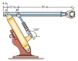
The industrial robot is held in the stationary position shown. Draw the shear and moment diagrams of the arm ABC if it is pin connected at A and connected to a hydraulic cylinder (twoforce member) BD. Assume the arm and grip have a uniform weight of 1.5 lb/in. and support the load of 40 lb at C. 4
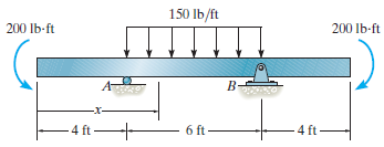
Draw the shear and moment diagrams for the beam and determine the shear and moment in the beam as functions of x, where 4 ft < x < 10 ft. 150 Ib/ft 200 lb-ft 200 Ib-ft B- 4 ft ft- 6 ft 4 ft
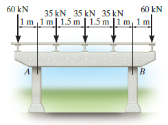
A reinforced concrete pier is used to support the stringers for a bridge deck. Draw the shear and moment diagrams for the pier. Assume the columns at A and B exert only vertical reactions on the pier. 60 kN 60 kN 35 kN 35 kN 35 kN 1m ,1 m| 1.5 m 1.5 m 1 m, 1m
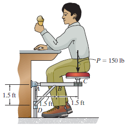
Members ABC and BD of the counter chair are rigidly connected at B and the smooth collar at D is allowed to move freely along the vertical post. Draw the shear and moment diagrams for member ABC. -P = 150 lb 1.5 ft 1.5 ft TD
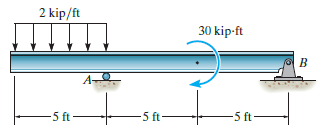
Draw the shear and moment diagrams for the beam. 2 kip/ft 30 kip-ft -5 ft- -5 ft -5 ft
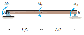
Draw the shear and moment diagrams for the beam. Mo Mo L/2- -L/2
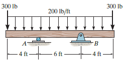
Draw the shear and moment diagrams for the beam. 300 Ib 300 lb 200 lb/ft 4 ft 6 ft 4 ft
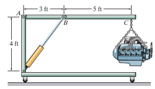
The crane is used to support the engine, which has a weight of 1200 lb. Draw the shear and moment diagrams of the boom ABC when it is in the horizontal position. - 3 ft – -5 ft- 4 ft
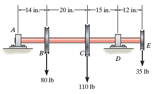
Draw the shear and moment diagrams for the shaft. The bearings at A and D exert only vertical reactions on the shaft. -15 in.12 in.- 20 in. -14 in- A в н D 35 lb 80 lb 110 lb
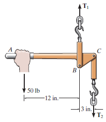
If the force applied to the handle of the load binder is 50 lb, determine the tensions T1and T2in each end of the chain and then draw the shear and moment diagrams for the arm ABC. 50 lb F12 in.- 3 in. T2
Draw the shear and moment diagrams for the beam, and determine the shear and moment throughout the beam as functions of x for 0 ≤ x ≤ 6 ft and 6 ft ≤ x ≤ 9 ft.
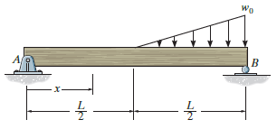
Express the internal shear and moment in terms of x for 0 ‰¤ x < L/2, and L/2 < x 6 L, and then draw the shear and moment diagrams. Wo X-
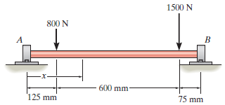
Draw the shear and moment diagrams for the shaft. The bearings at A and B exert only vertical reactions on the shaft. Also, express the shear and moment in the shaft as a function of x within the region 125 mm < x < 725 mm. 1500 N 800 N A 600 mm 75 mm 125 mm
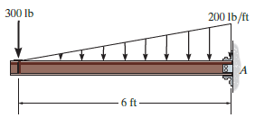
Express the internal shear and moment in the cantilevered beam as a function of x and then draw the shear and moment diagrams. 300 Ib 200 lb/ft 6 ft
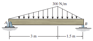
Express the shear and moment in terms of x for 0 < x < 3 m and 3 m < x < 4.5 m, and then draw the shear and moment diagrams for the simply supported beam. 300 N/m 1.5 m
Draw the shear and moment diagrams for the beam, and determine the shear and moment throughout the beam as functions of x for 0 ≤ x ≤ 6 ft and 6 ft ≤ x ≤ 10 ft.
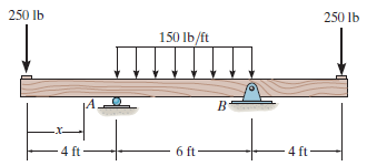
Draw the shear and moment diagrams for the beam, and determine the shear and moment in the beam as functions of x for 0 ‰¤ x < 4 ft, 4 ft < x < 10 ft, and 10 ft < x < 14 ft. 250 Ib 250 lb 150 Ib/ft -4 ft- 4 ft 6 ft-
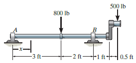
Draw the shear and moment diagrams for the shaft and determine the shear and moment throughout the shaft as a function of x for 0 ‰¤ x < 3 ft, 3 ft < x < 5 ft, and 5 ft < x < 6 ft. The bearings at A and B exert only vertical reactions on the shaft. 500 Ib 800 lb -3 ft-
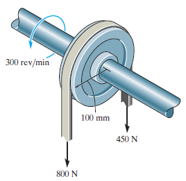
The 60-mm-diameter shaft rotates at 300 rev/min. This motion is caused by the unequal belt tensions on the pulley of 800 N and 450 N. Determine the power transmitted and the maximum shear stress developed in the shaft. 300 rev/min 100 mm 450 N 800 N
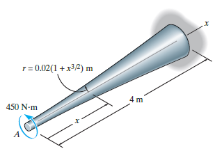
The tapered shaft is made from 2014-T6 aluminum alloy, and has a radius which can be described by the equation r = 0.02(1 + x3/2) m, where x is in meters. Determine the angle of twist of its end A if it is subjected to a torque of 450 N ˆ™ m. r= 0.02(1 +x32) m 4 m 450 N-m
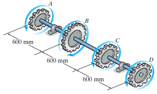
Gear B supplies 15 kW of power, while gears A, C and D withdraw 6 kW, 4 kW and 5 kW, respectively. If the shaft is made of steel with the allowable shear stress of Ï„allow= 75 MPa, and the relative angle of twist between any two gears cannot exceed 0.05 rad, determine the required minimum
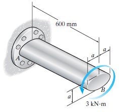
If the shaft is subjected to the torque of 3 kN ˆ™ m, determine the maximum shear stress developed in the shaft. Also, find the angle of twist of end B. The shaft is made from A-36 steel. Set a = 50 mm. 600 mm 3 kN-m
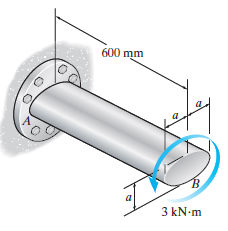
If the shaft is made from A-36 steel having an allowable shear stress of Ï„allow= 75 MPa, determine the minimum dimension a for the cross section to the nearest millimeter. Also, find the corresponding angle of twist at end B. 600 mm 3 kN-m
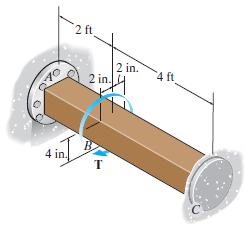
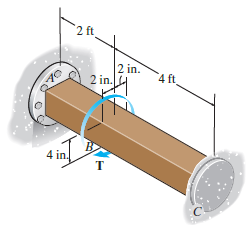
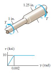
If the solid shaft is made from red brass C83400 having an allowable shear stress of Ï„allow= 4 ksi, determine the maximum allowable torque T that can be applied at B. 2 ft 2 in. 2 in. 4 ft 70 4 in.
If the solid shaft is made from red brass C83400 and it is subjected to a torque T = 6 kip # ft at B, determine the maximum shear stress developed in segments AB and BC. 2 ft 2 in. 2 in. 4 ft 70 4 in. 2.
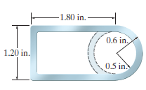
For a given maximum average shear stress, determine the factor by which the torque-carrying capacity is increased if the half-circular section is reversed from the dashed-line position to the section shown. The tube is 0.1 in. thick. -1.80 in.- 0,6 in. 1.20 in. 0.5 in
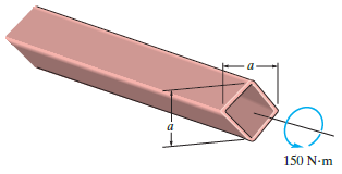
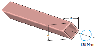
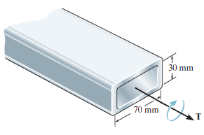
The plastic tube is subjected to a torque of 150 N ˆ™ m. Determine the mean dimension a of its sides if the allowable shear stress is Ï„allow= 60 MPa. Each side has a thickness of t = 3 mm. 150 N-m
The plastic tube is subjected to a torque of 150 N ˆ™ m. Determine the average shear stress in the tube if the mean dimension a = 200 mm. Each side has a thickness of t = 3 mm. 150 N-m
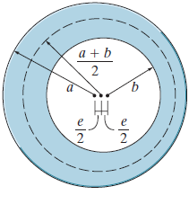
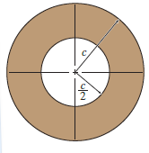
Due to a fabrication error the inner circle of the tube is eccentric with respect to the outer circle. By what percentage is the torsional strength reduced when the eccentricity e is one-fourth of the difference in the radii? a + b 2 -- -- ъ
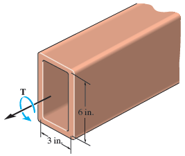
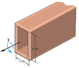
Determine the constant thickness of the rectangular tube if the average shear stress is not to exceed 12 ksi when a torque of T = 100 kip ˆ™ in. is applied to the tube. The mean dimensions of the tube are shown. 6 in. 3 in
Determine the torque T that can be applied to the rectangular tube if the average shear stress is not to exceed 12 ksi. The mean dimensions of the tube are shown and the tube has a thickness of 0.25 in. 6 in. 3 in
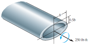
The steel tube has an elliptical cross section of mean dimensions shown and a constant thickness of t = 0.2 in. If the allowable shear stress is Ï„allow= 8 ksi, and the tube is to resist a torque of T = 250 lb ˆ™ ft, determine the necessary dimension b. The mean area for the
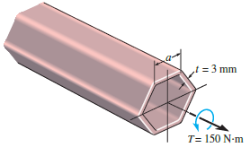
The plastic hexagonal tube is subjected to a torque of 150 N ˆ™ m. Determine the mean dimension a of its sides if the allowable shear stress is Ï„allow= 60 MPa. Each side has a thickness of t = 3 mm. = 3 mm T= 150 N-m
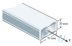
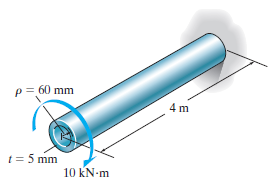
The 304 stainless steel tube has a thickness of 10 mm. If the allowable shear stress is Ï„allow= 80 MPa, determine the maximum torque T that it can transmit. Also, what is the angle of twist of one end of the tube with respect to the other if the tube is 4 m long? The mean dimensions are
The 304 stainless steel tube has a thickness of 10 mm. If the applied torque is T = 50 N # m, determine the average shear stress in the tube. The mean dimensions are shown. 30 mm 70 mm
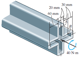
The symmetric tube is made from a high-strength steel, having the mean dimensions shown and a thickness of 5 mm. If it is subjected to a torque of T = 40 N ˆ™ m, determine the average shear stress developed at points A and B. Indicate the shear stress on volume elements located at these
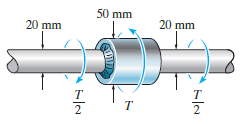
The steel step shaft has an allowable shear stress of Ï„allow= 8 MPa. If the transition between the cross sections has a radius r = 4 mm, determine the maximum torque T that can be applied. 50 mm 20 mm 20 mm т 2
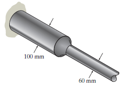
The built-up shaft is to be designed to rotate at 450 rpm while transmitting 230 kW of power. Is this possible? The allowable shear stress is Ï„allow= 150 MPa. 100 mm 60 mm
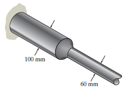
The built-up shaft is designed to rotate at 450 rpm. If the radius of the fillet weld connecting the shafts is r = 13.2 mm, and the allowable shear stress for the material is Ï„allow= 150 MPa, determine the maximum power the shaft can transmit. 100 mm 60 mm
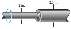
The shaft is used to transmit 30 hp while turning at 600 rpm. Determine the maximum shear stress in the shaft. The segments are connected together using a fillet weld having a radius of 0.18 in. 2,5 in. 2 in.
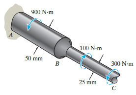
The shaft is fixed to the wall at A and is subjected to the torques shown. Determine the maximum shear stress in the shaft. A fillet weld having a radius of 2.75 mm is used to connect the shafts at B. 900 N-m 100 N-m 50 mm 300 N-m 25 mm
A solid shaft has a diameter of 40 mm and length of 1 m. It is made from an elastic-plastic material having a yield stress of tY = 100 MPa. Determine the maximum elastic torque TY and the corresponding angle of twist. What is the angle of twist if the torque is increased to T = 1.2TY? G = 80 GPa.
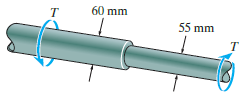
The stepped shaft is subjected to a torque T that produces yielding on the surface of the larger diameter segment. Determine the radius of the elastic core produced in the smaller diameter segment. Neglect the stress concentration at the fillet. 60 mm 55 mm
Determine the torque needed to twist a short 2-mm-diameter steel wire through several revolutions if it is made from steel assumed to be elastic perfectly plastic and having a yield stress of τY = 50 MPa. Assume that the material becomes fully plastic.
A bar having a circular cross section of 3 in.diameter is subjected to a torque of 100 in. # kip. If the material is elastic perfectly plastic, with τY = 16 ksi, determine the radius of the elastic core.
The solid shaft is made of an elastic perfectly plastic material. Determine the torque T needed to form an elastic core in the shaft having a radius of ÏY= 20 mm. If the shaft is 3 m long, through what angle does one end of the shaft twist with respect to the other end? When the torque
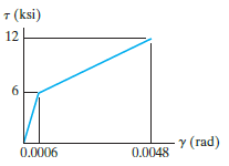
The shaft is subjected to a maximum shear strain of 0.0048 rad. Determine the torque applied to the shaft. 2 in.- т 7 (ksi) 12 Y (rad) 0.0006 0.0048
A circular shaft having a diameter of 4 in. is subjected to a torque of 250 kip # in. If the material is elastic perfectly plastic, with τY = 16 ksi, determine the radius of the elastic core.
The hollow shaft has the cross section shown and is made of an elastic perfectly plastic material having a yield shear stress of tY. Determine the ratio of the plastic torque Tpto the maximum elastic torque TY.
The 2-m-long tube is made of an elastic perfectly plastic material as shown. Determine the applied torque T, which subjects the material at the tube€™s outer edge to a shear strain of γmax= 0.006 rad. What would be the permanent angle of twist of the tube when this torque is
The 2-m-long tube is made of an elastic perfectly plastic material as shown. Determine the applied torque T, which subjects the material at the tube's outer edge to a shear strain of γmax= 0.006 rad. What would be the permanent angle of twist of the tube when this torque is removed? Sketch the
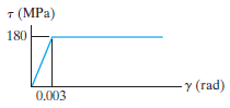
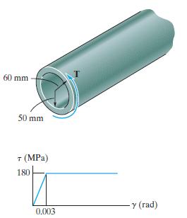
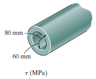
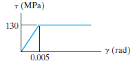
The tube has a length of 2 m and is made of an elastic perfectly plastic material as shown. Determine the torque needed to just cause the material to become fully plastic. What is the permanent angle of twist of the tube when this torque is removed? 80 mm 60 mm 7 (MPa) 7 (MPa) 130 y (rad) 0.005
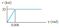
The 3-in.-diameter shaft is made of an elastic perfectly plastic material as shown. Determine the radius of its elastic core if it is subjected to a torque of T = 18 kip ˆ™ ft. If the shaft is 3 ft long, determine the angle of twist. т 3 ft т 7 (ksi) 33 Y (rad) 0.006
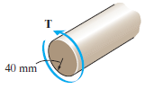
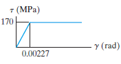
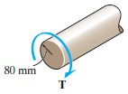
The shaft is made of an elastic perfectly plastic material as shown. Plot the shear-stress distribution acting along a radial line if it is subjected to a torque of T = 20 kN ˆ™ m. What is the residual stress distribution in the shaft when the torque is removed? т 40 mm (MPa) 170 y
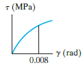
A torque is applied to the shaft having a radius of 80 mm. If the material obeys a shear stress€“strain relation of Ï„ = 500 γ¼MPa, determine the torque that must be applied to the shaft so that the maximum shear strain becomes 0.008 rad. 80 mm т 7 (MPa) Y
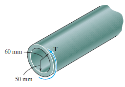
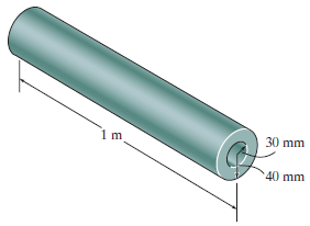
A tubular shaft has an inner diameter of 60 mm, an outer diameter of 80 mm, and a length of 1 m. It is made of an elastic perfectly plastic material having a yield stress of Ï„Y= 150 MPa. Determine the maximum torque it can transmit. What is the angle of twist of one end with respect to
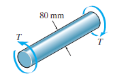
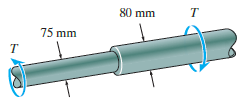
The stepped shaft is subjected to a torque T that produces yielding on the surface of the larger diameter segment. Determine the radius of the elastic core produced in the smaller diameter segment. Neglect the stress concentration at the fillet. т 80 mm 75 mm
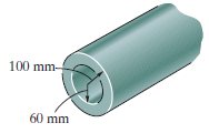
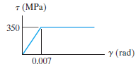
The tube has a length of 2 m and is made of an elastic perfectly plastic material as shown. Determine the torque needed to just cause the material to become fully plastic. What is the permanent angle of twist of the tube when this torque is removed? 100 mm- 60 mm 7 (MPa) 350 y (rad) 0.007
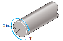
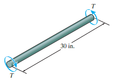
A shaft of radius c = 0.75 in. is made from an elastic perfectly plastic material as shown. Determine the torque T that must be applied to its ends so that it has an elastic core of radius Ï = 0.6 in. If the shaft is 30 in. long, determine the angle of twist. T. 30 in. т (ksi) 3 Y
The shaft consists of two sections that are rigidly connected. If the material is elastic perfectly plastic as shown, determine the largest torque T that can be applied to the shaft. Also, draw the shear-stress distribution over a radial line for each section. Neglect the effect of stress
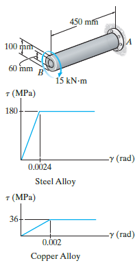
A steel alloy core is bonded firmly to the copper alloy tube to form the shaft shown. If the materials have the Ï„-γ diagrams shown, determine the torque resisted by the core and the tube. 450 mm 100 mm 60 mm 15 kN-m 7 (MPa) 180 -у (гad) 0.0024 Steel Alloy т (MPa) 36- -Y
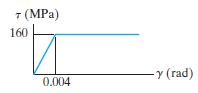
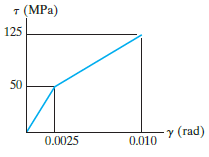
The shear stress€“strain diagram for a solid 50-mm-diameter shaft can be approximated as shown in the figure. Determine the torque required to cause a maximum shear stress in the shaft of 125 MPa. If the shaft is 3 m long, what is the corresponding angle of twist? т (MPа) 125 50 y (rad)
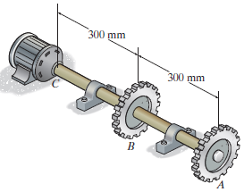
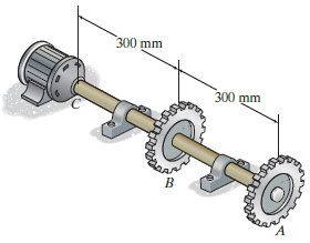
The shaft is made of A992 steel and has an allowable shear stress of Ï„allow= 75 MPa. When the shaft is rotating at 300 rpm, the motor supplies 8 kW of power, while gears A and B withdraw 5 kW and 3 kW, respectively. Determine the required minimum diameter of the shaft to the nearest
The shaft is made of A992 steel and has an allowable shear stress of Ï„allow= 75 MPa. When the shaft is rotating at 300 rpm, the motor supplies 8 kW of power, while gears A and B withdraw 5 kW and 3 kW, respectively. If the angle of twist of gear A relative to C is not allowed to exceed
The A-36 steel circular tube is subjected to a torque of 10 kN # m. Determine the shear stress at the mean radius Ï = 60 mm and calculate the angle of twist of the tube if it is 4 m long and fixed at its far end. Solve the problem using Eqs. 5€“7 and 5€“15 and by
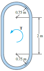
A portion of an airplane fuselage can be approximated by the cross section shown. If the thickness of its 2014-T6-aluminum skin is 10 mm, determine the maximum wing torque T that can be applied if Ï„allow= 4 MPa. Also, in a 4-m-long section, determine the angle of twist. 0.75 m 2m 0.75 m
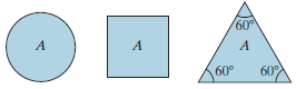
The material of which each of three shafts is made has a yield stress of Ï„Yand a shear modulus of G. Determine which shaft geometry will resist the largest torque without yielding. What percentage of this torque can be carried by the other two shafts? Assume that each shaft is made from
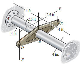
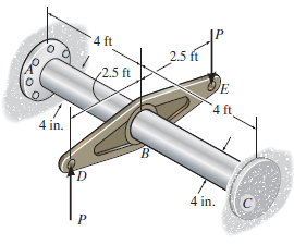
Segments AB and BC of the assembly are made from 6061-T6 aluminum and A992 steel, respectively. If couple forces P = 3 kip are applied to the lever arm, determine the maximum shear stress developed in each segment. The assembly is fixed at A and C. 4 ft 2.5 ft 2.5 ft 4 ft 4 in. B. 4 in. C.
Segments AB and BC of the assembly are made from 6061-T6 aluminum and A992 steel, respectively. If the allowable shear stress for the aluminum is (Ï„allow)al= 12 ksi and for the steel (Ï„allow)st= 10 ksi, determine the maximum allowable couple forces P that can be applied to the
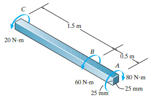
The 6061-T6 aluminum bar has a square cross section of 25 mm by 25 mm. If it is 2 m long, determine the maximum shear stress in the bar and the rotation of one end relative to the other end. 1.5 m 20 N-m d.5 m 80 N-m 60 N-m 25 mm 25 mm
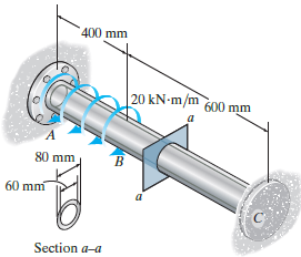
If the shaft is subjected to a uniform distributed torque of t = 20 kN ˆ™ m/m, determine the maximum shear stress developed in the shaft. The shaft is made of 2014-T6 aluminum alloy and is fixed at A and C. 400 mm 20 kN-m/m 600 mm B. 80 mm 60 mm Section a-a
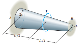
The tapered shaft is confined by the fixed supports at A and B. If a torque T is applied at its mid-point, determine the reactions at the supports. 20 -L/2- -L/2-
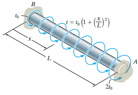
The shaft of radius c is subjected to a distributed torque t, measured as torque>length of shaft. Determine the reactions at the fixed supports A and B. to x=to(1 + (¥)*) 21o 2t0 B.
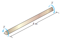
The brass wire has a triangular cross section, 2 mm on a side. If the yield stress for brass is tY= 205 MPa, determine the maximum torque T to which it can be subjected so that the wire will not yield. If this torque is applied to the 4-m-long segment, determine the greatest angle of twist of one
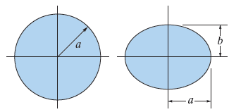
If a = 25 mm and b = 15 mm, determine the maximum shear stress in the circular and elliptical shafts when the applied torque is T = 80 N ˆ™ m. By what percentage is the shaft of circular cross section more efficient at withstanding the torque than the shaft of elliptical cross section?
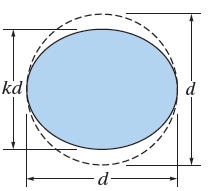
It is intended to manufacture a circular bar to resist torque; however, the bar is made elliptical in the process of manufacturing, with one dimension smaller than the other by a factor k as shown. Determine the factor by which the maximum shear stress is increased. kd d-
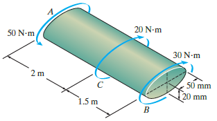
The shaft is made of red brass C83400 and has an elliptical cross section. If it is subjected to the torsional loading determine the maximum shear stress within regions AC and BC, and the angle of twist Ï• of end B relative to end A. 20 N-m 50 N-m 30 N-m 2 m 50 mm 20 mm 1.5 m
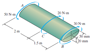
Solve Prob. 5€“98 for the maximum shear stress within regions AC and BC, and the angle of twist Ï• of end B relative to C. A. 20 N-m 50 N-m 30 N-m 50 mm mm 1.5 m
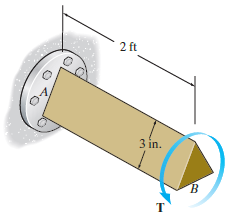
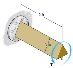
If end B of the shaft, which has an equilateral triangular cross section, is subjected to a torque of T = 900 lb ˆ™ ft, determine the maximum shear stress in the shaft. Also, find the angle of twist of end B. The shaft is made from 6061-T1 aluminum. 2 ft 3 in. т
If the shaft has an equilateral triangle cross section and is made from an alloy that has an allowable shear stress of Ï„allow= 12 ksi, determine the maximum allowable torque T that can be applied to end B. Also, find the corresponding angle of twist of end B. 2 ft 3 in. т
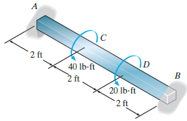
The 2014-T6 aluminum strut is fixed between the two walls at A and B. If it has a 2 in. by 2 in. square cross section, and it is subjected to the torsional loading shown, determine the reactions at the fixed supports. Also, what is the angle of twist at C? A 2 ft 40 Ib-ft 2 ft 20 lb-ft 2ft
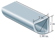
A torque of 2 kip ˆ™ in. is applied to the tube. If the wall thickness is 0.1 in., determine the average shear stress in the tube. 2 in. 2 in 1.90 in.
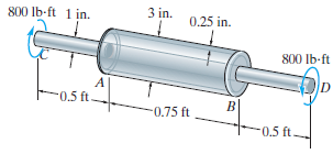
The composite shaft consists of a mid-section that includes the 1-in.-diameter solid shaft and a tube that is welded to the rigid flanges at A and B. Neglect the thickness of the flanges and determine the angle of twist of end C of the shaft relative to end D. The shaft is subjected to a torque of
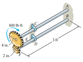
The two 3-ft-long shafts are made of 2014-16 aluminum. Each has a diameter of 1.5 in. and they are connected using the gears fixed to their ends. Their other ends are attached to fixed supports at A and B. They are also supported by bearings at C and D, which allow free rotation of the shafts along
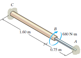
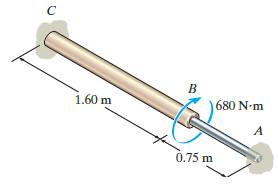
Determine the absolute maximum shear stress in the shaft of Prob. 5€“88.Prob. 5-88: A rod is made from two segments: AB is steel and BC is brass. It is fixed at its ends and subjected to a torque of T = 680 N ˆ™ m. If the steel portion has a diameter of 30 mm, determine the
A rod is made from two segments: AB is steel and BC is brass. It is fixed at its ends and subjected to a torque of T = 680 N ˆ™ m. If the steel portion has a diameter of 30 mm, determine the required diameter of the brass portion so the reactions at the walls will be the same. Gst= 75
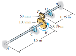
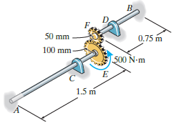
The two shafts are made of A-36 steel. Each has a diameter of 25 mm and they are connected using the gears fixed to their ends. Their other ends are attached to fixed supports at A and B. They are also supported by journal bearings at C and D, which allow free rotation of the shafts along their
The two shafts are made of A-36 steel. Each has a diameter of 25 mm and they are connected using the gears fixed to their ends. Their other ends are attached to fixed supports at A and B. They are also supported by journal bearings at C and D, which allow free rotation of the shafts along their
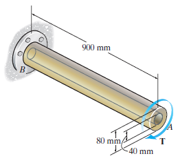
The Am1004-T61 magnesium tube is bonded to the A-36 steel rod. If a torque of T = 5 kN ˆ™ m is applied to end A, determine the maximum shear stress in each material. Sketch the shear stress distribution. 900 mm 80 mm т 40 mm
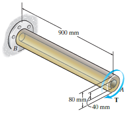
The Am1004-T61 magnesium tube is bonded to the A-36 steel rod. If the allowable shear stresses for the magnesium and steel are (Ï„allow)mg= 45 MPa and (Ï„allow)st= 75 MPa, respectively, determine the maximum allowable torque that can be applied at A. Also, find the corresponding
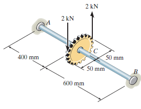
The shaft is made of L2 tool steel, has a diameter of 40 mm, and is fixed at its ends A and B. If it is subjected to the couple, determine the maximum shear stress in regions AC and CB. 2 kN 2 kN 50 mm 400 mm 50 mm 600 mm
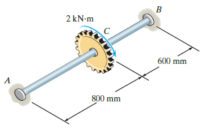
The shaft is made of L2 tool steel, has a diameter of 40 mm, and is fixed at its ends A and B. If it is subjected to the torque, determine the maximum shear stress in regions AC and CB. 2 kN-m 600 mm A 800 mm
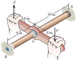
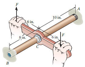
The bronze C86100 pipe has an outer diameter of 1.5 in. and a thickness of 0.125 in. The coupling on it at C is being tightened using a wrench. If the applied force is F = 20 lb, determine the maximum shear stress in the pipe. 10 in. 6 in. 6 in. 8 in.
The bronze C86100 pipe has an outer diameter of 1.5 in. and a thickness of 0.125 in. The coupling on it at C is being tightened using a wrench. If the torque developed at A is 125 lb ˆ™ in., determine the magnitude F of the couple forces. The pipe is fixed supported at end B. 10 in. 6 in.
Showing 500 - 600
of 983
1
2
3
4
5
6
7
8
9
10
Step by Step Answers