New Semester
Started
Get
50% OFF
Study Help!
--h --m --s
Claim Now
Question Answers
Textbooks
Find textbooks, questions and answers
Oops, something went wrong!
Change your search query and then try again
S
Books
FREE
Study Help
Expert Questions
Accounting
General Management
Mathematics
Finance
Organizational Behaviour
Law
Physics
Operating System
Management Leadership
Sociology
Programming
Marketing
Database
Computer Network
Economics
Textbooks Solutions
Accounting
Managerial Accounting
Management Leadership
Cost Accounting
Statistics
Business Law
Corporate Finance
Finance
Economics
Auditing
Tutors
Online Tutors
Find a Tutor
Hire a Tutor
Become a Tutor
AI Tutor
AI Study Planner
NEW
Sell Books
Search
Search
Sign In
Register
study help
sciences
mechanics of materials
Mechanics Of Materials 10th Edition Russell C. Hibbeler - Solutions
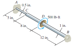
The steel shaft is made from two segments: AC has a diameter of 0.5 in, and CB has a diameter of 1 in. If the shaft is fixed at its ends A and B and subjected to a torque of 500 lb # ft, determine the maximum shear stress in the shaft. Gst= 10.8(103) ksi. 0.5 in. D_ 500 Ib-ft 5 in. 1 in. 8 in. 12
The A992 steel shaft has a diameter of 60 mm and is fixed at its ends A and B. If it is subjected to the torques shown, determine the absolute maximum shear stress in the shaft.
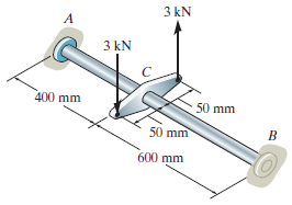
The steel shaft has a diameter of 40 mm and is fixed at its ends A and B. If it is subjected to the couple, determine the maximum shear stress in regions AC and CB of the shaft. Gst= 75 GPa. 3 kN A 3 kN 400 mm 50 mm 50 mm 600 mm
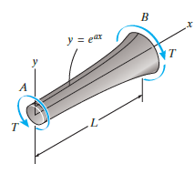
The contour of the surface of the shaft is defined by the equation y = eax, where a is a constant. If the shaft is subjected to a torque T at its ends, determine the angle of twist of end A with respect to end B. The shear modulus is G. х Ув еar т т
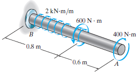
The 60-mm-diameter solid shaft is made of A-36 steel and is subjected to the distributed and concentrated torsional loadings shown. Determine the angle of twist at the free end A of the shaft due to these loadings. 2 kN-m/m 600 N - m 400 N-m 0.8 m 0.6 m
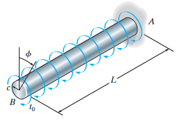
The shaft has a radius c and is subjected to a torque per unit length of t0, which is distributed uniformly over the shaft€™s entire length L. If it is fixed at its far end A, determine the angle of twist Ï• of end B. The shear modulus is G. A В
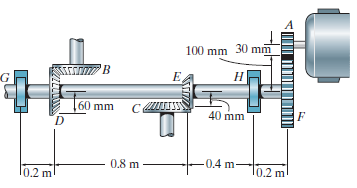
The motor produces a torque of T = 20 N ˆ™ m on gear A. If gear C is suddenly locked so it does not turn, yet B can freely turn, determine the angle of twist of F with respect to E and F with respect to D of the L2-steel shaft, which has an inner diameter of 30 mm and an outer diameter of
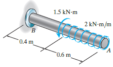
The 60-mm-diameter solid shaft is made of 2014-T6 aluminum and is subjected to the distributed and concentrated torsional loadings shown. Determine the angle of twist at the free end A of the shaft. 1.5 kN-m 2 KN•M/m 0.4 m 0.6 m
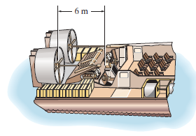
The tubular drive shaft for the propeller of a hovercraft is 6 m long. If the motor delivers 4 MW of power to the shaft when the propellers rotate at 25 rad/s, determine the required inner diameter of the shaft if the outer diameter is 250 mm. What is the angle of twist of the shaft when it is
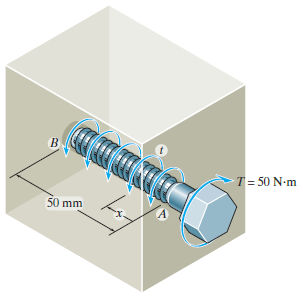
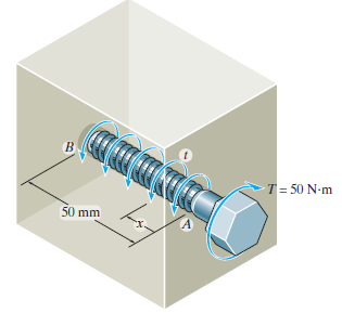
The A-36 steel bolt is tightened within a hole so that the reactive torque on the shank AB can be expressed by the equation t = (kx2/3) N ˆ™ m/m, where x is in meters. If a torque of T = 50 N ˆ™ m is applied to the bolt head, determine the constant k and the amount of twist in
The A-36 steel bolt is tightened within a hole so that the reactive torque on the shank AB can be expressed by the equation t = (kx2) N ˆ™ m/m, where x is in meters. If a torque of T = 50 N ˆ™ m is applied to the bolt head, determine the constant k and the amount of twist in the
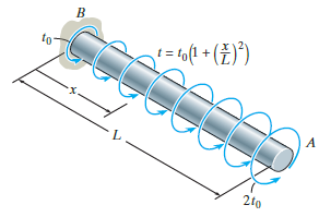
The shaft of radius c is subjected to a distributed torque t, measured as torque/length of shaft. Determine the angle of twist at end A. The shear modulus is G. t= to(1 + (ž)°) to 2to
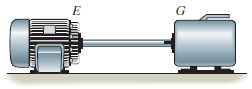
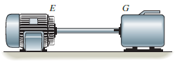
The A-36 solid steel shaft is 3 m long and has a diameter of 50 mm. It is required to transmit 35 kW of power from the engine E to the generator G. Determine the smallest angular velocity of the shaft if it is restricted not to twist more than 1°. וו Iשןש
The A-36 hollow steel shaft is 2 m long and has an outer diameter of 40 mm. When it is rotating at 80 rad/s, it transmits 32 kW of power from the engine E to the generator G. Determine the smallest thickness of the shaft if the allowable shear stress is Ï„allow= 140 MPa and the shaft is
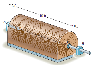
The 6-in.-diameter L-2 steel shaft on the turbine is supported on journal bearings at A and B. If C is held fixed and the turbine blades create a torque on the shaft that increases linearly from zero at C to 2000 lb ˆ™ ft at D, determine the angle of twist of the shaft at D relative to C.
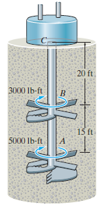
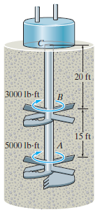
The device shown is used to mix soils in order to provide in-situ stabilization. If the mixer is connected to an A-36 steel tubular shaft that has an inner diameter of 3 in. and an outer diameter of 4.5 in, determine the angle of twist of the shaft at A relative to B and the absolute maximum shear
The device shown is used to mix soils in order to provide in-situ stabilization. If the mixer is connected to an A-36 steel tubular shaft that has an inner diameter of 3 in. and an outer diameter of 4.5 in., determine the angle of twist of the shaft at A relative to C if each mixing blade is
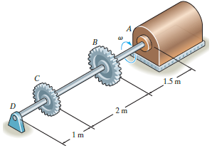
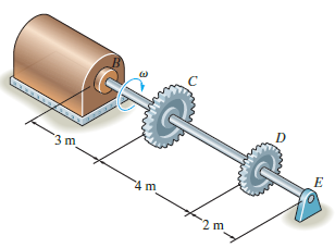
The turbine develops 300 kW of power, which is transmitted to the gears such that both B and C receive an equal amount. If the rotation of the 100-mm-diameter A992 steel shaft is ω = 600 rev/min., determine the absolute maximum shear stress in the shaft and the rotation of end D of the
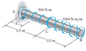
The A992 steel shaft has a diameter of 50 mm and is subjected to the distributed loadings shown. Determine the absolute maximum shear stress in the shaft and plot a graph of the angle of twist of the shaft in radians versus x. 500 N-m A 1000 N-m/m 0.5 m B. 0.5 m
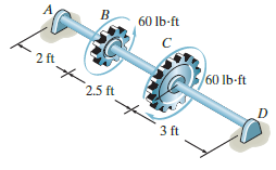
The shaft is made of A-36 steel. It has a diameter of 1 in. and is supported by bearings at A and D, which allow free rotation. Determine the angle of twist of gear C with respect to B. B 60 lb-ft 2 ft 60 lb-ft 2.5 ft 3 ft
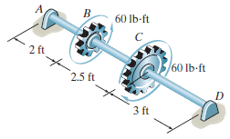
The shaft is made of A992 steel. It has a diameter of 1 in. and is supported by bearings at A and D, which allow free rotation. Determine the angle of twist of B with respect to D. 60 lb-ft 2 ft /60 lb-ft 2.5 ft 3 ft
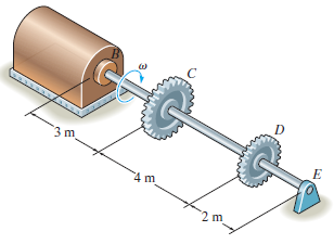
The turbine develops 150 kW of power, which is transmitted to the gears such that both C and D receive an equal amount. If the rotation of the 100-mm-diameter A-36 steel shaft is ω = 500 rev/min., determine the absolute maximum shear stress in the shaft and the rotation of end B of the
The turbine develops 150 kW of power, which is transmitted to the gears such that C receives 70% and D receives 30%. If the rotation of the 100-mm-diameter A-36 steel shaft is ω = 800 rev/min., determine the absolute maximum shear stress in the shaft and the angle of twist of end E of
The rotating flywheel-and-shaft, when brought to a sudden stop at D, begins to oscillate clockwise-counter-clockwise such that a point A on the outer edge of the fly-wheel is displaced through a 6-mm arc. Determine the maximum shear stress developed in the tubular A-36 steel shaft due to this
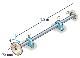
The shaft is made of A992 steel with the allowable shear stress of Ï„allow= 75 MPa. If gear B supplies 15 kW of power, while gears A, C and D withdraw 6 kW, 4 kW and 5 kW, respectively, determine the required minimum diameter d of the shaft to the nearest millimeter. Also, find the
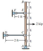
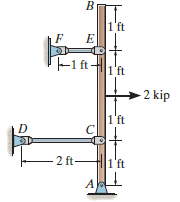
The rigid bar is pinned at A and supported by two aluminum rods, each having a diameter of 1 in. and a modulus of elasticity Eal= 10(103) ksi. If the bar is initially vertical, determine the displacement of the end B when the force of 2 kip is applied. 1 ft T-1 ftI'ft 2 kip 1'ft - 2 ft- 1'ft
The rigid bar is pinned at A and supported by two aluminum rods, each having a diameter of 1 in. and a modulus of elasticity Eal= 10(103) ksi. If the bar is initially vertical, determine the force in each rod when the 2-kip load is applied. T-1 ftH 1'ft kip -2 ft-
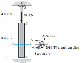
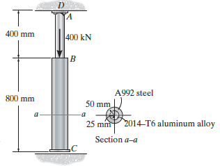
The 2014-T6 aluminum rod AC is reinforced with the firmly bonded A992 steel tube BC. If the assembly fits snugly between the rigid supports so that there is no gap at C, determine the support reactions when the axial force of 400 kN is applied. The assembly is attached at D. [A 400 mm 400 kN A992
The 2014-T6 aluminum rod AC is reinforced with the firmly bonded A992 steel tube BC. When no load is applied to the assembly, the gap between end C and the rigid support is 0.5 mm. Determine the support reactions when the axial force of 400 kN is applied.
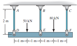
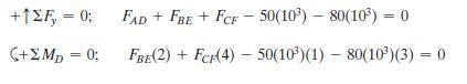
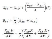
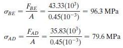
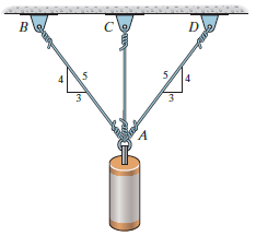
The three suspender bars are made of A992 steel and have equal cross-sectional areas of 450 mm2. Determine the average normal stress in each bar if the rigid beam is subjected to the loading shown. 80 kN 50 kN 2 m D Hm--1 m--1 m--1m-|
Referring to the FBD of the rigid beam, Fig. a,Referring to the geometry shown in Fig. b,FAD + FCF = 2 FBESolving Eqs. (1), (2), and (3) yieldsFBE = 43.33(103) N FAD = 35.83(103) N FCF = 50.83(103) NThus, σCF = 113 MPa +12F, = 0; FAD + FBE + FCF - 50(10)
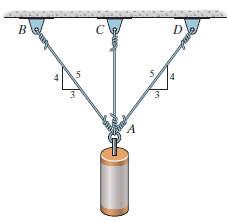
The three A-36 steel wires each have a diameter of 2 mm and unloaded lengths of LAC= 1.60 m and LAB= LAD= 2.00 m. Determine the force in each wire after the 150-kg mass is suspended from the ring at A. cle 5,
The A-36 steel wires AB and AD each have a diameter of 2 mm and the unloaded lengths of each wire are LAC = 1.60 m and LAB = LAD = 2.00 m. Determine the required diameter of wire AC so that each wire is subjected to the same force when the 150-kg mass is suspended from the ring at A. B C D 3 A
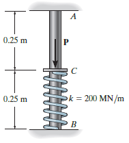
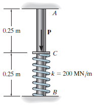
The post is made from 606l-T6 aluminum and has a diameter of 50 mm. It is fixed supported at A and B, and at its center C there is a coiled spring attached to the rigid collar. If the spring is originally uncompressed, determine the reactions at A and B when the force P = 40 kN is applied to the
The post is made from 606l-T6 aluminum and has a diameter of 50 mm. It is fixed supported at A and B, and at its center C there is a coiled spring attached to the rigid collar. If the spring is originally uncompressed, determine the compression in the spring when the load of P = 50 kN is applied to
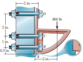
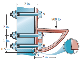
The bracket is held to the wall using three A-36 steel bolts at B, C, and D. Each bolt has a diameter of 0.5 in. and an unstretched length of 2 in. If a force of 800 lb is placed on the bracket as shown, determine the force developed in each bolt. For the calculation, assume that the bolts carry no
The bracket is held to the wall using three A-36 steel bolts at B, C, and D. Each bolt has a diameter of 0.5 in. and an unstretched length of 2 in. If a force of 800 lb is placed on the bracket as shown, determine how far, s, the top bracket at bolt D moves away from the wall. For the calculation,
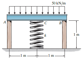
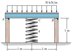
The rigid bar is supported by the two short white spruce wooden posts and a spring. If each of the posts has an unloaded length of 1 m and a cross-sectional area of 600 mm2, and the spring has a stiffness of k = 2 MN/m and an unstretched length of 1.02 m, determine the force in each post after the
The rigid bar is supported by the two short white spruce wooden posts and a spring. If each of the posts has an unloaded length of 1 m and a cross-sectional area of 600 mm2, and the spring has a stiffness of k = 2 MN >m and an unstretched length of 1.02 m, determine the vertical displacement of
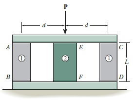
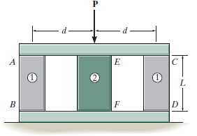
The assembly consists of two posts AB and CD each made from material 1 having a modulus of elasticity of E1and a cross-sectional area A1, and a central post made from material 2 having a modulus of elasticity E2and cross-sectional area A2. If a load P is applied to the rigid cap, determine the
The assembly consists of two posts AB and CD each made from material 1 having a modulus of elasticity of E1and a cross-sectional area A1, and a central post EF made from material 2 having a modulus of elasticity E2and a cross-sectional area A2. If posts AB and CD are to be replaced by those having
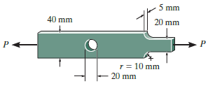
If the allowable normal stress for the bar is σallow= 120 MPa, determine the maximum axial force P that can be applied to the bar. 5 mm 40 mm 20 mm r = 10 mm 20 mm
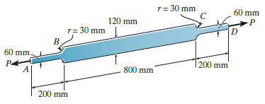
The A-36 steel plate has a thickness of 12 mm. If σallow= 150 MPa, determine the maximum axial load P that it can support. Calculate its elongation, neglecting the effect of the fillets. r= 30 mm 60 mm 120 mm r= 30 mm 60 mm. 200 mm 800 mm 200 mm
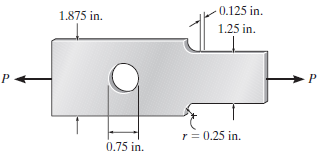
Determine the maximum axial force P that can be applied to the bar. The bar is made from steel and has an allowable stress of σallow= 21 ksi. 0.125 in. 1.875 in. 1.25 in. r = 0.25 in. 0.75 in.
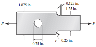
Determine the maximum normal stress developed in the bar when it is subjected to a tension of P = 2 kip. 0.125 in. 1.875 in. 1.25 in. r = 0.25 in. 0.75 in.
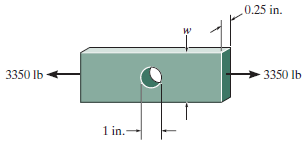
The member is to be made from a steel plate that is 0.25 in. thick. If a 1-in. hole is drilled through its center, determine the approximate width w of the plate so that it can support an axial force of 3350 lb. The allowable stress is σallow= 22 ksi. 0.25 in. и 3350 Ib 3350 lb 1 in.
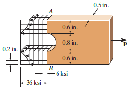
The resulting stress distribution along section AB for the bar is shown. From this distribution, determine the approximate resultant axial force P applied to the bar. Also, what is the stress concentration factor? 0.5 in. 0.6 in. 0.8 in. P. 0.2 in. 0.6 in. - 6 ksi - 36 ksi -
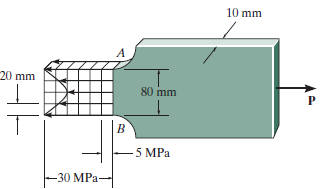
The resulting stress distribution along section AB for the bar is shown. From this distribution, determine the approximate resultant axial force P applied to the bar. Also, what is the stress concentration factor? 10 mm 20 mm 80 mm 5 MPa -30 MPa-
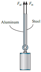
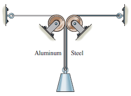
The weight is suspended from steel and aluminum wires, each having the same initial length of 3 m and cross-sectional area of 4 mm2. If the materials can be assumed to be elastic perfectly plastic, with (σY)st= 120 MPa and (σY)al= 70 MPa, determine the force in each wire if
The weight is suspended from steel and aluminum wires, each having the same initial length of 3 m and cross-sectional area of 4 mm2. If the materials can be assumed to be elastic perfectly plastic, with (σY)st= 120 MPa and (σY)al= 70 MPa, determine the force in each wire if
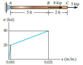
The bar has a cross-sectional area of 0.5 in2and is made of a material that has a stress€“strain diagram that can be approximated by the two line segments. Determine the elongation of the bar due to the applied loading. B 8 kip C 5 kip - 2 ft ft o (ksi) 40 20 e (in/in.) 0,001 0.021 B 8
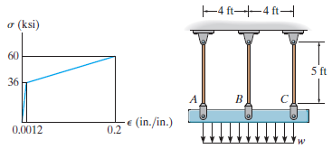
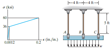
The distributed loading is applied to the rigid beam, which is supported by the three bars. Each bar has a cross-sectional area of 1.25 in2and is made from a material having a stress€“strain diagram that can be approximated by the two line segments. If a load of w = 25 kip/ft is applied
The distributed loading is applied to the rigid beam, which is supported by the three bars. Each bar has a cross-sectional area of 0.75 in2and is made from a material having a stress€“ strain diagram that can be approximated by the two line segments. Determine the intensity of the
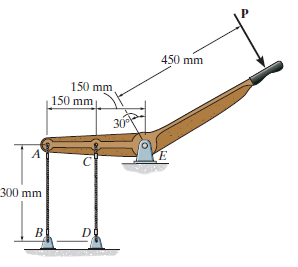
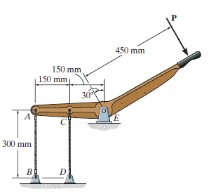
The rigid lever arm is supported by two A-36 steel wires having the same diameter of 4 mm. If a force of P = 3 kN is applied to the handle, determine the force developed in both wires and their corresponding elongations. Consider A-36 steel as an elastic perfectly plastic material. 450 mm 150 mm
The rigid lever arm is supported by two A-36 steel wires having the same diameter of 4 mm. Determine the smallest force P that will cause(a) Only one of the wires to yield;(b) Both wires to yield. Consider A-36 steel as an elastic perfectly plastic material 450 mm 150 mm 150 mm 30 E. 300 mm в B. D.
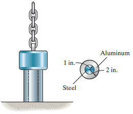
The 300-kip weight is slowly set on the top of a post made of 2014-T6 aluminum with an A-36 steel core. If both materials can be considered elastic perfectly plastic, determine the average normal stress in each material. Aluminum 1 in. 2 in. Steel
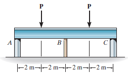
The rigid beam is supported by three 25-mm diameter A-36 steel rods. If the beam supports the force of P = 230 kN, determine the force developed in each rod. Consider the steel to be an elastic perfectly plastic material. [D 600 mm -400 mm---400 mm- 400 mm-
The rigid beam is supported by three 25-mm diameter A-36 steel rods. If the force of P = 230 kN is applied on the beam and removed, determine the residual stresses in each rod. Consider the steel to be an elastic perfectly plastic material. D 600 mm -400 mm---400 mm- 400 mm--
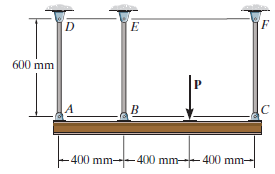
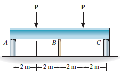
The rigid beam is supported by the three posts A, B, and C of equal length. Posts A and C have a diameter of 75 mm and are made of a material for which E = 70 GPa and σY= 20 MPa. Post B has a diameter of 20 mm and is made of a material for which E' = 100 GPa and σY' = 590 MPa.
The rigid beam is supported by the three posts A, B, and C. Posts A and C have a diameter of 60 mm and are made of a material for which E = 70 GPa and σY= 20 MPa. Post B is made of a material for which E' = 100 GPa and σY' = 590 MPa. If P = 130 kN, determine the diameter of
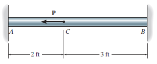
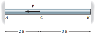
The bar having a diameter of 2 in. is fixed connected at its ends and supports the axial load P. If the material is elastic perfectly plastic as shown by the stress€“strain diagram, determine the smallest load P needed to cause segment CB to yield. If this load is released, determine the
Determine the elongation of the bar in Prob. 4€“108 when both the load P and the supports are removed. B -2 ft -3 ft
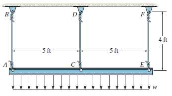
The rigid beam is supported by three A-36 steel wires, each having a length of 4 ft. The cross-sectional area of AB and EF is 0.015 in2, and the cross-sectional area of CD is 0.006 in2. Determine the largest distributed load w that can be supported by the beam before any of the wires begin to
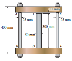
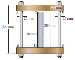
The assembly consists of two A992 steel bolts AB and EF and an 6061-T6 aluminum rod CD. When the temperature is at 30° C, the gap between the rod and rigid member AE is 0.1 mm. Determine the normal stress developed in the bolts and the rod if the temperature rises to 130° C. Assume BF is
The assembly shown consists of two A992 steel bolts AB and EF and an 6061-T6 aluminum rod CD. When the temperature is at 30° C, the gap between the rod and rigid member AE is 0.1 mm. Determine the highest temperature to which the assembly can be raised without causing yielding either in the rod
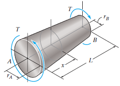
The solid shaft has a linear taper from rAat one end to rBat the other. Derive an equation that gives the maximum shear stress in the shaft at a location x along the shaft€™s axis. Тв
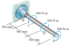
The 50-mm-diameter A992 steel shaft is subjected to the torques shown. Determine the angle of twist of the end A. 400 N-m 200 N-m 300 mm 800 N-m 600 mm 600 mm
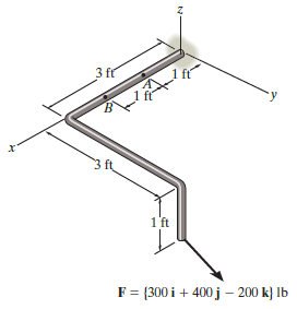
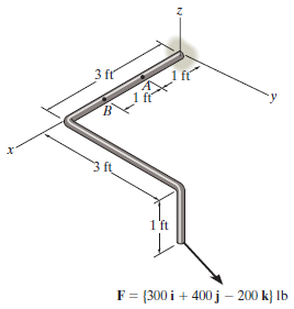
The 1-in.-diameter bent rod is subjected to the load shown. Determine the maximum torsional stress in the rod at a section located through A. 3 fr 3 ft 1 ft F = {300 i + 400 j – 200 k} lb
The 1-in.-diameter bent rod is subjected to the load shown. Determine the maximum torsional stress in the rod at B. 3 fr х 3 ft 1'ft F%3 [300і + 400 j - 200 k) lb
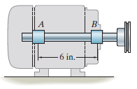
A motor delivers 500 hp to the shaft, which is tubular and has an outer diameter of 2 in. If it is rotating at 200 rad/s, determine its largest inner diameter to the nearest 1/8 in. if the allowable shear stress for the material is Ï„allow= 25 ksi. B- A - 6 in.-
The propellers of a ship are connected to an A-36 steel shaft that is 60 m long and has an outer diameter of 340 mm and inner diameter of 260 mm. If the power output is 4.5 MW when the shaft rotates at 20 rad/s, determine the maximum torsional stress in the shaft and its angle of twist.
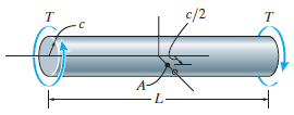
The solid shaft of radius c is subjected to a torque T at its ends. Show that the maximum shear strain in the shaft is γmax= Tc/JG. What is the shear strain on an element located at point A, c/2 from the center of the shaft? Sketch the shear strain distortion of this element. c/2
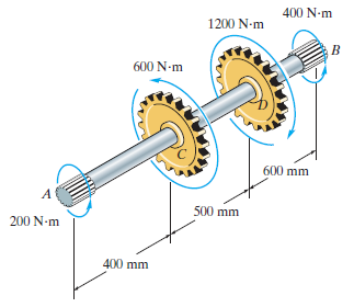
The splined ends and gears attached to the A992 steel shaft are subjected to the torques shown. Determine the angle of twist of end B with respect to end A. The shaft has a diameter of 40 mm. 400 N-m 1200 N-m 600 N-m 600 mm 500 mm 200 N-m 400 mm
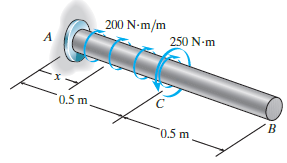
The A-36 steel shaft has a diameter of 50 mm and is subjected to the distributed and concentrated loadings shown. Determine the absolute maximum shear stress in the shaft and plot a graph of the angle of twist of the shaft in radians versus x. _200 N-m/m 250 N-m 0.5 m '0.5 m
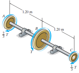
The 60-mm-diameter shaft is made of 6061-T6 aluminum having an allowable shear stress of Ï„allow= 80 MPa. Determine the maximum allowable torque T. Also, find the corresponding angle of twist of disk A relative to disk C. 1.20 m 1.20 m B. 3т
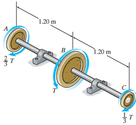
The 60-mm-diameter shaft is made of 6061-T6 aluminum. If the allowable shear stress is Ï„allow= 80 MPa, and the angle of twist of disk A relative to disk C is limited so that it does not exceed 0.06 rad, determine the maximum allowable torque T. 1.20 m 1.20 m B. 3т T.
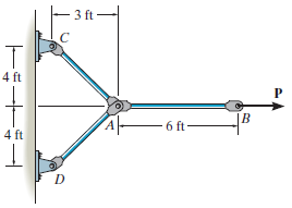
The linkage is made of three pin-connected A992 steel members, each having a diameter of 1¼ in. Determine the magnitude of the force P needed to displace point B 0.25 in. to the right. t – - 3 ft 4 ft |B - 6 ft- 4 ft
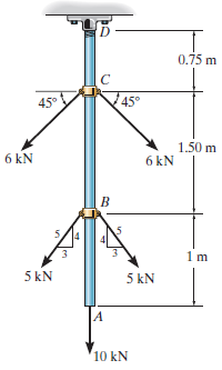
The A992 steel rod is subjected to the loading shown. If the cross-sectional area of the rod is 80 mm2, determine the displacement of B and A. Neglect the size of the couplings at B and C. 0,75 m 45° 45° 1.50 m 6 kN 6 kN B. 5 kN 5 kN 10 kN
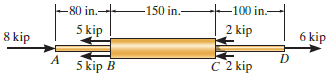
The copper shaft is subjected to the axial loads shown. Determine the displacement of end A with respect to end D if the diameters of each segment are dAB= 0.75 in., dBC= 1 in., and dCD= 0.5 in. Take Ecu= 18(103) ksi. -80 in. -150 in. -100 in.- 5 kip 2 kip 6 kip 8 kip A 5 kip B C 2 kip
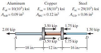
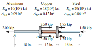
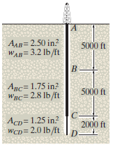
The composite shaft, consisting of aluminum, copper, and steel sections, is subjected to the loading shown. Determine the displacement of end A with respect to end D and the normal stress in each section. The cross-sectional area and modulus of elasticity for each section are shown in the figure.
The composite shaft, consisting of aluminum, copper, and steel sections, is subjected to the loading shown. Determine the displacement of B with respect to C. The cross-sectional area and modulus of elasticity for each section are shown in the figure. Neglect the size of the collars at B and C.
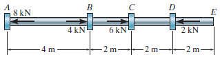
The 2014-T6 aluminium rod has a diameter of 30 mm and supports the load shown. Determine the displacement of end A with respect to end E. Neglect the size of the couplings. 8 kN 2 kN 6 kN 4 kNY -2m- 2 m- 4 m 2 m-
The A-36 steel drill shaft of an oil well extends 12 000 ft into the ground. Assuming that the pipe used to drill the well is suspended freely from the derrick at A, determine the maximum average normal stress in each pipe string and the elongation of its end D with respect to the fixed end at A.
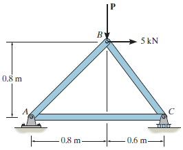
The truss is made of three A-36 steel members, each having a cross-sectional area of 400 mm2. Determine the horizontal displacement of the roller at C when P = 8 kN. 5 kN 0.8m 0.8 m. 0,6 m-
The truss is made of three A-36 steel members, each having a cross-sectional area of 400 mm2. Determine the magnitude P required to displace the roller to the right 0.2 mm.
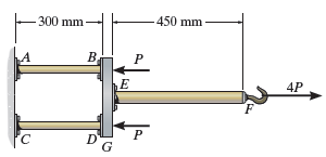
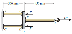
The assembly consists of two 10-mm diameter red brass C83400 copper rods AB and CD, a 15-mm diameter 304 stainless steel rod EF, and a rigid bar G. If P = 5 kN, determine the horizontal displacement of end F of rod EF. -450 mm- - 300 mm B. LA 4P DG
The assembly consists of two 10-mm diameter red brass C83400 copper rods AB and CD, a 15-mm diameter 304 stainless steel rod EF, and a rigid bar G. If the horizontal displacement of end F of rod EF is 0.45 mm, determine the magnitude of P.Discuss. 450 mm -300 mm- 4P
The assembly consists of two 10-mm diameter red brass C83400 copper rods AB and CD, a 15-mm diameter 304 stainless steel rod EF, and a rigid bar G. If the horizontal displacement of end F of rod EF is 0.45 mm, determine the magnitude of P. 450 mm -300 mm- 4P
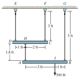
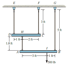
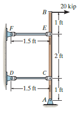
The load is supported by the four 304 stainless steel wires that are connected to the rigid members AB and DC. Determine the vertical displacement of the 500-lb load if the members were originally horizontal when the load was applied. Each wire has a cross-sectional area of 0.025 in2. 3 ft 5 ft D
The load is supported by the four 304 stainless steel wires that are connected to the rigid members AB and DC. Determine the angle of tilt of each member after the 500-lb load is applied. The members were originally horizontal, and each wire has a cross-sectional area of 0.025 in2. 3 ft 5 ft Н |
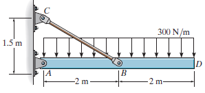
The rigid bar is supported by the pin-connected rod CB that has a cross-sectional area of 14 mm2and is made from 6061-T6 aluminum. Determine the vertical deflection of the bar at D when the distributed load is applied. 300 N/m IN||||| 1.5 m -2 m- -2 m
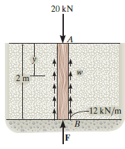
The post is made of Douglas fir and has a diameter of 100 mm. If it is subjected to the load of 20 kN and the soil provides a frictional resistance distributed around the post that is triangular along its sides; that is, it varies from w = 0 at y = 0 to w = 12 kN/m at y = 2 m, determine the force F
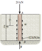
The post is made of Douglas fir and has a diameter of 100 mm. If it is subjected to the load of 20 kN and the soil provides a frictional resistance that is distributed along its length and varies linearly from w = 4 kN/m at y = 0 to w =12 kN/m at y = 2 m, determine the force F at its bottom needed
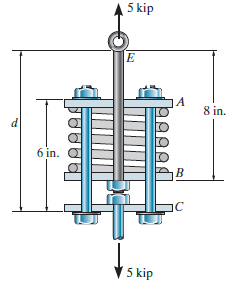
The coupling rod is subjected to a force of 5 kip. Determine the distance d between C and E accounting for the compression of the spring and the deformation of the bolts. When no load is applied the spring is unstretched and d = 10 in. The material is A-36 steel and each bolt has a diameter of 0.25
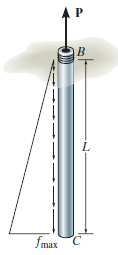
The pipe is stuck in the ground so that when it is pulled upward the frictional force along its length varies linearly from zero at B to fmax(force/length) at C. Determine the initial force P required to pull the pipe out and the pipe€™s elongation just before it starts to slip. The pipe
The linkage is made of three pin-connected A992 steel members, each having a diameter of 1¼ in. If a horizontal force of P = 60 kip is applied to the end B of member AB, determine the displacement of point B. |B 6 ft
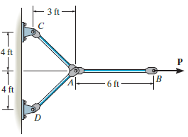
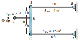
The assembly consists of three titanium (Ti-6A1-4V) rods and a rigid bar AC. The cross-sectional area of each rod is given in the figure. If a force of 60 kip is applied to the ring F, determine the horizontal displacement of point F. 6 ft AAB = 1 in? Agr = 2 in? 1 ft 60 kip F-2 ft 2'ft AcD = 1.5
The rigid bar is pinned at A and supported by two aluminum rods, each having a diameter of 1 in. a modulus of elasticity Eal= 10(103) ksi, and yield stress of (σY)al= 40 ksi. If the bar is initially vertical, determine the angle of tilt of the bar when the 20-kip load is applied. 20 kip
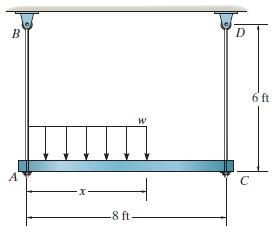
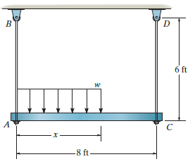
The rigid beam is supported at its ends by two A-36 steel tie rods. If the allowable stress for the steel is σallow= 16.2 ksi, the load w = 3 kip/ft, and x = 4 ft, determine the smallest diameter of each rod so that the beam remains in the horizontal position when it is loaded. 6 ft 8 ft-
The rigid beam is supported at its ends by two A-36 steel tie rods. The rods have diameters dAB= 0.5 in. and dCD= 0.3 in. If the allowable stress for the steel is σallow= 16.2 ksi, determine the largest intensity of the distributed load w and its length x on the beam so that the beam
Showing 600 - 700
of 983
1
2
3
4
5
6
7
8
9
10
Step by Step Answers