New Semester
Started
Get
50% OFF
Study Help!
--h --m --s
Claim Now
Question Answers
Textbooks
Find textbooks, questions and answers
Oops, something went wrong!
Change your search query and then try again
S
Books
FREE
Study Help
Expert Questions
Accounting
General Management
Mathematics
Finance
Organizational Behaviour
Law
Physics
Operating System
Management Leadership
Sociology
Programming
Marketing
Database
Computer Network
Economics
Textbooks Solutions
Accounting
Managerial Accounting
Management Leadership
Cost Accounting
Statistics
Business Law
Corporate Finance
Finance
Economics
Auditing
Tutors
Online Tutors
Find a Tutor
Hire a Tutor
Become a Tutor
AI Tutor
AI Study Planner
NEW
Sell Books
Search
Search
Sign In
Register
study help
sciences
mechanics of materials
Mechanics Of Materials 10th Edition Russell C. Hibbeler - Solutions
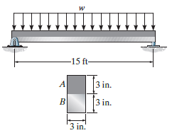
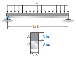
Segment A of the composite beam is made from 2014-T6 aluminum alloy and segment B is A-36 steel. The allowable bending stress for the aluminum and steel are (σallow)al= 15 ksi and (σallow)st= 22 ksi. Determine the maximum allowable intensity w of the uniform distributed load.
Segment A of the composite beam is made from 2014-T6 aluminum alloy and segment B is A-36 steel. If w = 0.9 kip/ft, determine the absolute maximum bending stress in the aluminum and steel. Sketch the stress distribution on the cross section. и -15 ft- 3 in. 3 in. 3 in.
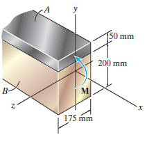
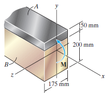
The composite beam is made of steel (A) bonded to brass (B) and has the cross section shown. If the allowable bending stress for the steel is (σallow)st= 180 MPa, and for the brass (σallow)br= 60 MPa, determine the maximum moment M that can be applied to the beam. Ebr= 100
The composite beam is made of steel (A) bonded to brass (B) and has the cross section shown. If it is subjected to a moment of M = 6.5 kN ˆ™ m, determine the maximum bending stress in the brass and steel. Also, what is the stress in each material at the seam where they are bonded
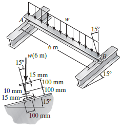
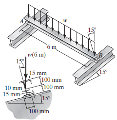
Determine the maximum allowable intensity w of the uniform distributed load that can be applied to the beam. Assume w passes through the centroid of the beam€™s crosssectional area, and the beam is simply supported at A and B. The allowable bending stress is σallow= 165 MPa. 6
If the applied distributed loading of w = 4 kN/m can be assumed to pass through the centroid of the beam€™s cross-sectional area, determine the absolute maximum bending stress in the joist and the orientation of the neutral axis. The beam can be considered simply supported at A and B.
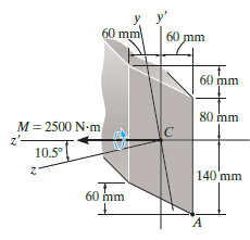
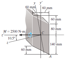
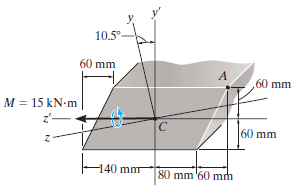
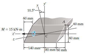
Solve Prob. 6€“116 using the equation developed in Prob. 6€“106. 60 mm 60 mm 60 mm 80 mm M = 2500 N-m 10.5° 140 mm 60 mm
For the section, Iy'= 31.7(10€“6) m4, Iz'= 114(10€“6) m4, Iy'z'= 15.8(10€“6) m4. Using the techniques outlined in Appendix A, the member€™s cross-sectional area has principal moments of inertia of Iy= 28.8(10€“6) m4and Iz= 117(10€“6) m4,
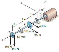
The shaft is subjected to the vertical and horizontal loadings of two pulleys D and E as shown. It is supported on two journal bearings at A and B which offer no resistance to axial loading. Furthermore, the coupling to the motor at C can be assumed not to offer any support to the shaft. Determine
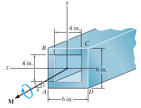
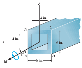
Determine the maximum magnitude of the bending moment M so that the bending stress in the member does not exceed 15 ksi. 4 in. 4 in. 6 in. ID -6 in.-
The box beam is subjected to a moment of M = 15 kip ˆ™ ft. Determine the maximum bending stress in the beam and the orientation of the neutral axis. y 4 in. 4 in. 6 in. ID -6 in.-
Solve Prob. 6€“111 using the equation developed in Prob. 6€“106.Data from 6-106For the section, Iz' = 31.7(10ˆ’6) m4, Iy' = 114(10ˆ’6) m4, Iy'z' = ˆ’15.8(10ˆ’6) m4. Using the techniques outlined in Appendix A, the member€™s
For the section, Iz'= 31.7(10ˆ’6) m4, Iy' = 114(10ˆ’6) m4, Iy'z'= ˆ’15.8(10ˆ’6) m4. Using the techniques outlined in Appendix A, the member€™s cross-sectional area has principal moments of inertia of Iz= 28.8(10ˆ’6) m4and Iy=
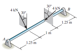
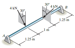
The 65-mm-diameter steel shaft is subjected to the two loads. If the journal bearings at A and B do not exert an axial force on the shaft, determine the absolute maximum bending stress developed in the shaft. 30° 4 kN. 4 kN 30°, 1.25 m 1.25 m
The steel shaft is subjected to the two loads. If the journal bearings at A and B do not exert an axial force on the shaft, determine the required diameter of the shaft if the allowable bending stress is σallow= 180 MPa. 30° 4 kN 4 kN 30° 1.25 m 1.25 m
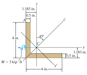
Determine the bending stress at point A of the beam using the result obtained in Prob. 6€“106. The moments of inertia of the cross-sectional area about the z and y axes are Iz= Iy= 5.561 in4and the product of inertia of the cross sectional area with respect to the z and y axes is Iyz=
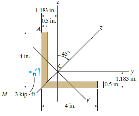
Determine the bending stress at point A of the beam, and the orientation of the neutral axis. Using the method in Appendix A, the principal moments of inertia of the cross section are Iz' = 8.828 in4and Iy' = 2.295 in4, where z' and y' are the principal axes. Solve the problem using Eq.
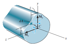
Consider the general case of a prismatic beam subjected to bendingmoment components Myand Mzwhen the x, y, z axes pass through the centroid of the cross section. If the material is linear elastic, the normal stress in the beam is a linear function of position such that σ = a + by + cz.
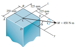
The member has a square cross section and is subjected to the moment M = 850 N ˆ™ m as shown. Determine the stress at each corner and sketch the stress distribution. Set θ = 30°. 125 mm 125 mm 250 mm M = 850 N-m
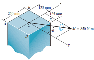
The member has a square cross section and is subjected to the moment M = 850 N ˆ™ m. Determine the stress at each corner and sketch the stress distribution. Set θ = 45°. î25 mm 125 mm 250 mm M = 850 N-m
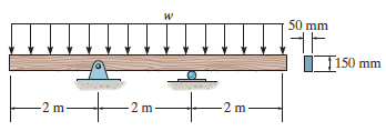
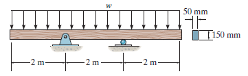
The beam has the rectangular cross section shown. If w = 1 kN/m, determine the maximum bending stress in the beam. Sketch the stress distribution acting over the cross section. 50 mm НЕ I T150 mm -2 2 m 2 m 2 m
The beam has a rectangular cross section as shown. Determine the largest intensity w of the uniform distributed load so that the bending stress in the beam does not exceed σmax= 10 MPa. 50 mm IT150 mm -2 m- -2 m -2 m-
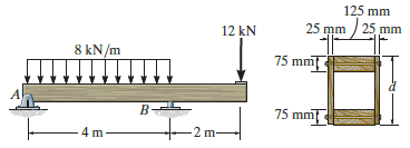
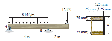
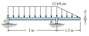
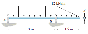
If the allowable bending stress is σallow= 6 MPa, determine the minimum dimension d of the beam€™s cross€‘sectional area to the nearest mm. 125 mm 25 mm / 25 mm 75 mm 12 kN 8 kN/m 75 mm B- 2 m- 4m
If d = 450 mm, determine the absolute maximum bending stress in the overhanging beam. 25 mm / 25 mm 12 kN 75 mm 8 kN/m A B B- 75 mm 4 m 2 m
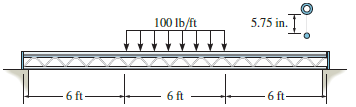
The simply supported truss is subjected to the central distributed load. Neglect the effect of the diagonal lacing and determine the absolute maximum bending stress in the truss. The top member is a pipe having an outer diameter of 1 in. and thickness of 3/16 in., and the bottom member is a solid
If the beam in Prob. 6–3 has a rectangular cross section with a width of 8 in. and a height of 16 in., determine the absolute maximum bending stress in the beam.
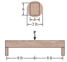
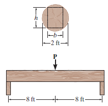
A log that is 2 ft in diameter is to be cut into a rectangular section for use as a simply supported beam. If the allowable bending stress is σallow= 8 ksi, determine the largest load P that can be supported if the width of the beam is b = 8 in. -b- 2 ft- E8 ft- E8 ft
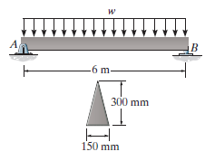
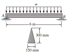
If the intensity of the load w = 15 kN/m, determine the absolute maximum tensile and compressive stress in the beam. -6 m- 300 mm 150 mm
If the allowable bending stress is σallow= 150 MPa, determine the maximum intensity w of the uniform distributed load. -6 m– 300 mm 150 mm
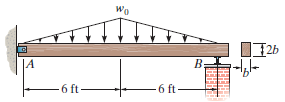
The beam is subjected to the triangular distributed load with a maximum intensity of w0= 300 lb/ft. If the allowable bending stress is σallow= 1.40 ksi, determine the required dimension b of its cross section to the nearest 1/8 in. Assume the support at A is a pin and B is a roller. Wo
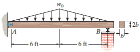
The beam has a rectangular cross section with b = 4 in. Determine the largest maximum intensity w0of the triangular distributed load that can be supported if the allowable bending stress is σallow= 1.40 ksi. Wo B. JA 6 ft 6 ft-
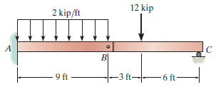
Determine the absolute maximum bending stress in the beam. Each segment has a rectangular cross section with a base of 4 in. and height of 12 in. 12 kip 2 kip/ft 9 ft -3 ft- 6 ft-
If the compound beam in Prob. 6–42 has a square cross section of side length a, determine the minimum value of a if the allowable bending stress is σallow = 150 MPa.
If the beam in Prob. 6–28 has a rectangular cross section with a width b and a height h, determine the absolute maximum bending stress in the beam.
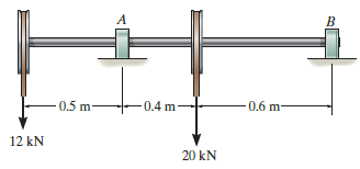
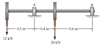
Determine the absolute maximum bending stress in the 80-mm-diameter shaft which is subjected to the concentrated forces. There is a journal bearing at A and a thrust bearing at B. A 0.5 m -0.6 m- 0.4 m- 12 kN 20 kN
Determine, to the nearest millimeter, the smallest allowable diameter of the shaft which is subjected to the concentrated forces. There is a journal bearing at A and a thrust bearing at B. The allowable bending stress is σallow= 150 MPa. -0.4 m 0.6 m- 0.5 m 12 kN 20 kN
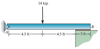
Determine the absolute maximum bending stress in the beam, assuming that the support at B exerts a uniformly distributed reaction on the beam. The cross section is rectangular with a base of 3 in. and height of 6 in. 14 kip B –3 ft- -4.5 ft- -4.5 ft-
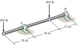
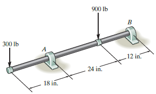
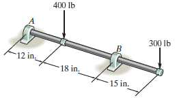
Determine the absolute maximum bending stress in the 2-in.-diameter shaft. There is a journal bearing at A and a thrust bearing at B. 900 Ib 300 lb 12 in. 24 in. 18 in.
Determine the smallest diameter of the shaft to the nearest 1/8 in. There is a journal bearing at A and a thrust bearing at B. The allowable bending stress is σallow= 22 ksi. 900 lb 300 lb A 12 in. 24 in. 18 in.
A log that is 2 ft in diameter is to be cut into a rectangular section for use as a simply supported beam. If the allowable bending stress is σallow= 8 ksi, determine the required width b and height h of the beam that will support the largest load possible. What is this load? -b- -2 ft-
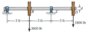
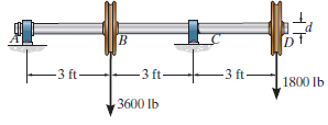
The shaft is supported by a thrust bearing at A and journal bearing at C. If the material has an allowable bending stress of σallow= 24 ksi, determine the required minimum diameter d of the shaft to the nearest 1/16 in. [B Dt -3 ft- 3 ft- -3 ft 1800 lb 3600 lb
The shaft is supported by a smooth thrust bearing at A and smooth journal bearing at C. If d = 3 in., determine the absolute maximum bending stress in the shaft. в -3 ft -3 ft -3 ft- 1800 lb 3600 Ib
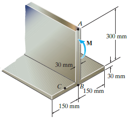
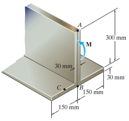
If the beam is made of material having an allowable tensile and compressive stress of (σallow)t= 125 MPa and (σallow)c= 150 MPa, respectively, determine the maximum moment M that can be applied to the beam. 300 mm 30 mm 30 mm TB 150 mm 150 mm
If the beam is subjected to a moment of M = 100 kN ˆ™ m, determine the bending stress at points A, B, and C. Sketch the bending stress distribution on the cross section. 300 mm 30 mm 30 mm 150 mm 150 mm
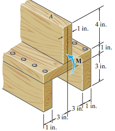
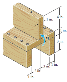
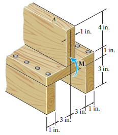
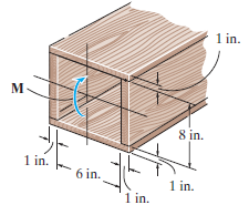
If the beam is subjected to an internal moment of M = 2 kip ˆ™ ft, determine the resultant force of the bending stress distribution acting on the top board A. 4 in. -1 in. in. M. 3 in. 1 in. 3 in! .3 in! 1 in.
If the allowable tensile and compressive stress for the beam are (σallow)t= 2 ksi and (σallow)c= 3 ksi, respectively, determine the maximum moment M that can be applied on the cross section. 4 in. -1 in. |1 in. M. 3 in. 1 in. 3 in! 3 in! 1 in.
If the beam is subjected to an internal moment of M = 2 kip ˆ™ ft, determine the maximum tensile and compressive stress in the beam. Also, sketch the bending stress distribution on the cross section. 4 in. L1 in. 1 in. M. 3 in. 1 in. 3 in! .3 in! 1 in.
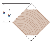
A timber beam has a cross section which is originally square. If it is oriented as shown, determine the dimension h€‘ so that it can resist the maximum moment possible. By what factor is this moment greater than that of the beam without its top or bottom flattened? h
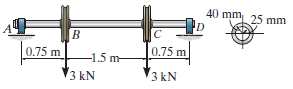
The shaft is supported by a thrust bearing at A and journal bearing at D. If the shaft has the cross section shown, determine the absolute maximum bending stress in the shaft. 40 mm 25 mm D. 0.75 m 0.75 m -1.5 m- 3 kN 3 kN
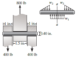
The pin is used to connect the three links together. Due to wear, the load is distributed over the top and bottom of the pin as shown on the free-body diagram. If the diameter of the pin is 0.40 in., determine the maximum bending stress on the cross-sectional area at the center section
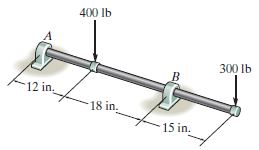
Determine the smallest allowable diameter of the shaft. The shaft is supported by a thrust bearing at A and a journal bearing at B. The allowable bending stress is σallow= 22 ksi. 400 lb 300 lb -12 in, 18 in. 15 in.
Determine the absolute maximum bending stress in the 1.5-in.-diameter shaft. The shaft is supported by a thrust bearing at A and a journal bearing at B. 400 Ib 300 lb 12 in 18 in. 15 in.
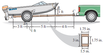
The boat has a weight of 2300 lb and a center of gravity at G. If it rests on the trailer at the smooth contact A and can be considered pinned at B, determine the absolute maximum bending stress developed in the main strut of the trailer which is pinned at C. Consider the strut to be a box-beam
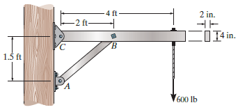
The strut on the utility pole supports the cable having a weight of 600 lb. Determine the absolute maximum bending stress in the strut if A, B, and C are assumed to be pinned. 2 in. -4 ft- -2 ft C01 in. 1.5 ft 600 lb
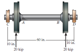
The axle of the freight car is subjected to a wheel loading of 20 kip. If it is supported by two journal bearings at C and D, determine the maximum bending stress developed at the center of the axle, where the diameter is 5.5 in. 60 in.- 10 in. 10 in. 20 kip 20 kip
The shaft is supported by smooth journal bearings at A and B that only exert vertical reactions on the shaft. Determine its smallest diameter d if the allowable bending stress is σallow= 180 MPa. 12 kN/m B. 1.5 m
The shaft is supported by smooth journal bearings at A and B that only exert vertical reactions on the shaft. If d = 90 mm, determine the absolute maximum bending stress in the beam, and sketch the stress distribution acting over the cross section. 12 kN/m B. B. -1.5 m 3 m
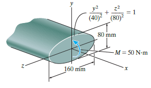
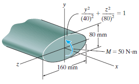
Solve Prob. 6€“65 if the moment M = 50 N ˆ™ m is applied about the y axis instead of the x axis. Here Iy= 1/4 Ï€ (0.04 m)(0.08 m)3.Data from 6-65A shaft is made of a polymer having an elliptical cross section. If it resists an internal moment of M = 50 N ˆ™
A shaft is made of a polymer having an elliptical cross section. If it resists an internal moment of M = 50 N ˆ™ m, determine the maximum bending stress in the material(a) Using the flexure formula, where Iz = ¼ Ï€(0.08 m)(0.04 m)3,(b) Using integration. Sketch a
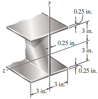
The beam is made of steel that has an allowable stress of σallow= 24 ksi. Determine the largest internal moment the beam can resist if the moment is applied (a) About the z axis, (b) About the y axis. 0.25 in. 3 in. 0.25 in 3 in. T0.25 in. 3 in 3 in.
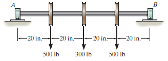
The steel shaft has a diameter of 2 in. It is supported on smooth journal bearings A and B, which exert only vertical reactions on the shaft. Determine the absolute maximum bending stress in the shaft if it is subjected to the pulley loadings shown. -20 in.--20 in- 20 in. 20 in.- 500 lb 300 Ib 500
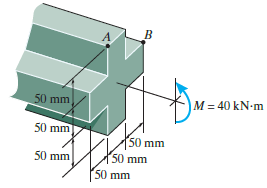
The beam is subjected to a moment of M = 40 kN ˆ™ m. Determine the bending stress at points A and B. Sketch the results on a volume element acting at each of these points. 50 mm M = 40 kN-m 50 mm 50 mm 50 mm 50 mm 50 mm
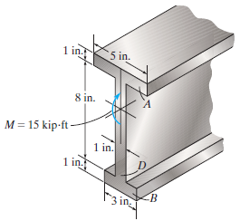
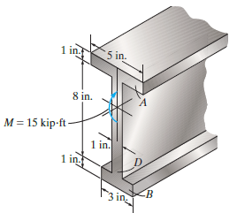
The beam is subjected to a moment of 15 kip ˆ™ ft. Determine the percentage of this moment that is resisted by the web D of the beam. 1 in. 5 in. 8 in. M = 15 kip-ft- 1 in. 1 in. 3 in
The beam is subjected to a moment of 15 kip ˆ™ ft. Determine the resultant force the bending stress produces on the top flange A and bottom flange B. Also calculate the maximum bending stress developed in the beam. 1 in. 5 in. 8 in. M = 15 kip-ft- 1 in. 1 in. 3 in.
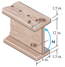
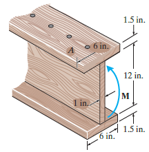
If M = 1 kip ˆ™ ft, determine the resultant force the bending stresses produce on the top board A of the beam. 1.5 in. o 6 in. 12 in. м 1 in. A 1.5 in. 6 in.
The beam is made from three boards nailed together as shown. If the moment acting on the cross section is M = 1 kip ˆ™ ft, determine the maximum bending stress in the beam. Sketch a three-dimensional view of the stress distribution acting over the cross section. 1.5 in. o 6 in. 12 in. M 1
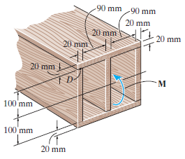
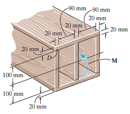
Determine the moment M that should be applied to the beam in order to create a compressive stress at point D of σD= 10 MPa. Also sketch the stress distribution acting over the cross section and calculate the maximum stress developed in the beam. 90 mm 90 mm 20 mm 20 mm 20 mm 20 mm 20 mm
The beam is subjected to a moment M. Determine the percentage of this moment that is resisted by the stresses acting on both the top and bottom boards of the beam. -90 mm 90 mm 20 mm 20 mm 20 mm 20 mm 20 mm 1 D- M. 100 mm 100 mm 20 mm
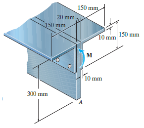
If the built-up beam is subjected to an internal moment of M = 75 kN ∙ m, determine the amount of this internal moment resisted by plate A.
If the built-up beam is subjected to an internal moment of M = 75 kN ˆ™ m, determine the maximum tensile and compressive stress acting in the beam. 150 mm 20 mm- 50 mm 150 mm 10 mm 10 mm 300 mm
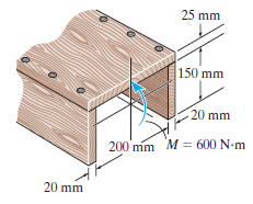
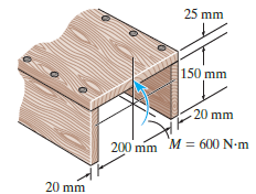
The beam is made from three boards nailed together as shown. If the moment acting on the cross section is M = 600 N ˆ™ m, determine the resultant force the bending stress produces on the top board. 25 mm 150 mm 20 mm 200 mm M = 600 N-m 20 mm
The beam is made from three boards nailed together as shown. If the moment acting on the cross section is M = 600 N ˆ™ m, determine the maximum bending stress in the beam. Sketch a three-dimensional view of the stress distribution and cover the cross section. 25 mm 150 mm 20 mm 200 mm M =
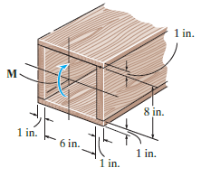
The beam is constructed from four pieces of wood, glued together as shown. If M = 10 kip ˆ™ ft, determine the resultant force this moment exerts on the top and bottom boards of the beam. 1 in. M 8 in. 1 in. 6 in. 1 in. 1 in.
The beam is constructed from four pieces of wood, glued together as shown. If M = 10 kip ˆ™ ft, determine the maximum bending stress in the beam. Sketch a threedimensional view of the stress distribution acting over the cross section. 1 in. м. 8 in. 1 in. 6 in. 1 in. 1 in.
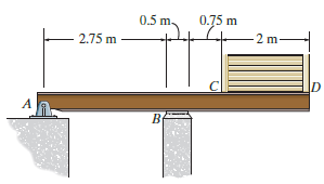
The beam is used to support a uniform load along CD due to the 6-kN weight of the crate. Also, the reaction at the bearing support B can be assumed uniformly distributed along its width. Draw the shear and moment diagrams for the beam. 0.75 m 0.5 m. 2 m 2.75 m A By
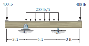
Draw the shear and moment diagrams for the double overhanging beam. 400 lb 400 Ib 200 lb/ft -3 ft 6 ft -3 ft-
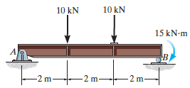
Draw the shear and moment diagrams for the simply supported beam. 10 kN 10 kN 15 kN-m -2 m -2 m 2 m
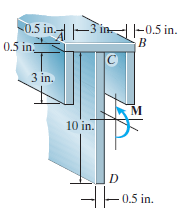
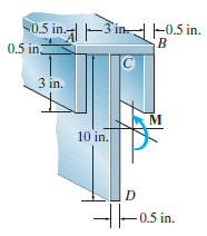
Determine the maximum tensile and compressive bending stress in the beam if it is subjected to a moment of M = 4 kip ˆ™ ft. -3 in- 0.5 in.- 0.5 in 3 in. м 10 in. D H-0.5 in.
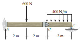
The compound beam is fixed at A, pin connected at B, and supported by a roller at C. Draw the shear and moment diagrams for the beam. 600 N 400 N/m hA |B -2 m- 2 m -2 m-
Determine the moment M that will produce a maximum stress of 10 ksi on the cross section. 0.5 in.--3 in- 0.5 in 0.5 in. 3 in. м 10 in. H-0.5 in.
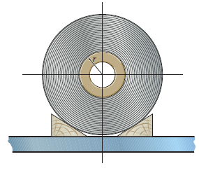
An A-36 steel strip has an allowable bending stress of 165 MPa. If it is rolled up, determine the smallest radius r of the spool if the strip has a width of 10 mm and a thickness of 1.5 mm. Also, find the corresponding maximum internal moment developed in the strip.
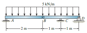
Draw the shear and moment diagrams for the compound beam. 5 kN/m I||||..|||| 2 m m
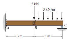
The compound beam is fixed at A, pin connected at B, and supported by a roller at C. Draw the shear and moment diagrams for the beam. 2 kN 3 kN/m |B iA 3 m 3 m
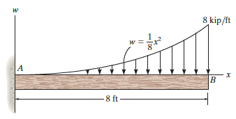
Draw the shear and moment diagrams for the beam. 8 kip/ft и B 8 ft -
A short link at B is used to connect beams AB and BC to form the compound beam. Draw the shear and moment diagrams for the beam if the supports at A and C are considered fixed and pinned, respectively.
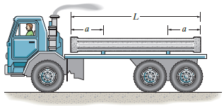
The truck is to be used to transport the concrete column. If the column has a uniform weight of w (force/length), determine the equal placement a of the supports from the ends so that the absolute maximum bending moment in the column is as small as possible. Also, draw the shear and moment diagrams
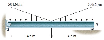
Draw the shear and moment diagrams for the beam. 50 kN/m 50 kN/m A| -4.5 m -4.5 m-
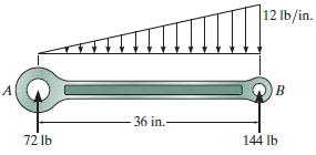
Draw the shear and moment diagrams for the rod. Only vertical reactions occur at its ends A and B. 12 lb/in. -36 in.- 72 lb 144 lb
Draw the shear and moment diagrams for the beam.
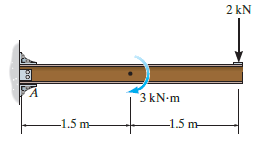
Draw the shear and moment diagrams for the cantilever beam. 2 kN 3 kN-m 1.5 m- -1.5 m-
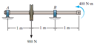
The shaft is supported by a smooth thrust bearing at A and smooth journal bearing at B. Draw the shear and moment diagrams for the shaft. 400 N-m A 1 m- -1m- -1m- 900 N
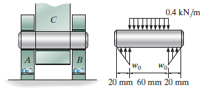
The smooth pin is supported by two leaves A and B and subjected to a compressive load of 0.4 kN/m caused by bar C. Determine the intensity of the distributed load w0of the leaves on the pin and draw the shear and moment diagram for the pin. 0.4 kN/m Wo 20 mm 60 mm 20 mm
The support at A allows the beam to slide freely along the vertical guide so that it cannot support a vertical force. Draw the shear and moment diagrams for the beam. |B
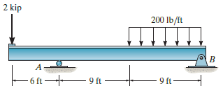
Draw the shear and moment diagrams for the beam. 2 kip kip 200 lb/ft - 6 ft H 9 ft 9 ft
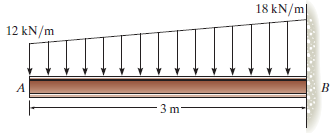
Draw the shear and moment diagrams for the beam. 18 kN/m 12 kN/m A 3 m
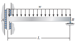
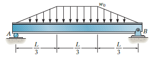
Draw the shear and moment diagrams for the beam. Wo A 3 3 3
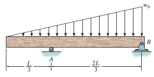
Draw the shear and moment diagrams for the beam. Wo
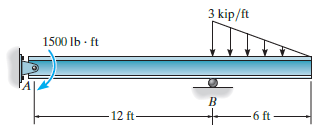
Draw the shear and moment diagrams for the beam. 3 kip/ft 1500 Ib · ft B 6 ft - -12 ft-
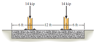
The footing supports the load transmitted by the two columns. Draw the shear and moment diagrams for the footing if the soil pressure on the footing is assumed to be uniform. 14 kip 14 kip -12 ft 6 ft -6 ft
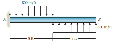
Draw the shear and moment diagrams for the beam.Discuss. 800 Ib/ft 800 lb/ft 8 ft- 8 ft
Showing 400 - 500
of 983
1
2
3
4
5
6
7
8
9
10
Step by Step Answers