New Semester
Started
Get
50% OFF
Study Help!
--h --m --s
Claim Now
Question Answers
Textbooks
Find textbooks, questions and answers
Oops, something went wrong!
Change your search query and then try again
S
Books
FREE
Study Help
Expert Questions
Accounting
General Management
Mathematics
Finance
Organizational Behaviour
Law
Physics
Operating System
Management Leadership
Sociology
Programming
Marketing
Database
Computer Network
Economics
Textbooks Solutions
Accounting
Managerial Accounting
Management Leadership
Cost Accounting
Statistics
Business Law
Corporate Finance
Finance
Economics
Auditing
Tutors
Online Tutors
Find a Tutor
Hire a Tutor
Become a Tutor
AI Tutor
AI Study Planner
NEW
Sell Books
Search
Search
Sign In
Register
study help
sciences
mechanics of materials
Mechanics Of Materials 10th Edition Russell C. Hibbeler - Solutions
The beam in Fig. 6–48f is subjected to a fully plastic moment Mp. Prove that the longitudinal and transverse shear stresses in the beam are zero. Hint: Consider an element of the beam shown in Fig. 7–4d.
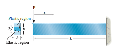
The beam has a rectangular cross section and is subjected to a load P that is just large enough to develop a fully plastic moment Mp= PL at the fixed support. If the material is elastic perfectly plastic, then at a distance x < L the moment M = Px creates a region of plastic yielding with an
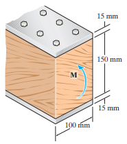
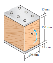
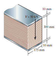
The composite beam is constructed from wood and reinforced with a steel strap. Use the method of Sec. 6.6 and calculate the maximum shear stress in the beam when it is subjected to a shear of V = 50 kN. Take Est= 200 GPa, Ew= 15 GPa. 10 mm V= 50 kN 300 mm 10 mm 175 mm
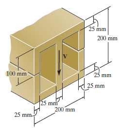
The beam is to be cut longitudinally along both sides as shown. If it is made from a material having an allowable shear stress of tallow = 75 MPa, determine the maximum allowable shear force V that can be applied before and after the cut is made. 25 mm 200 mm 25 mm 100 mm 25 mm 25 mm 200 mm 25 mm
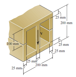
The beam is slit longitudinally along both sides. If it is subjected to a shear of V = 250 kN, compare the maximum shear stress in the beam before and after the cuts were made. 25 mm 200 mm 25 mm 100 mm mm 25 mm 200 mm 25 mm-
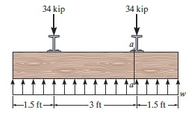
Railroad ties must be designed to resist large shear loadings. If the tie is subjected to the 34-kip rail loadings and an assumed uniformly distributed ground reaction, determine the intensity w for equilibrium, and calculate the maximum shear stress in the tie at section a€“a, which is
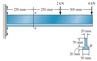
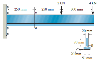
Determine the maximum shear stress acting at section a€“a of the cantilevered strut. 4 kN 2 kN 300 mm 250 mm 250 mm 20 mm 70 mm 20 mm 50 mm
Determine the shear stress at point B on the web of the cantilevered strut at section a€“a. 4 kN 2 kN 300 mm 250 mm a 250 mm 20 mm 70 mm 20 mm 50 mm
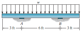
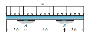
If w = 800 lb/ft, determine the absolute maximum shear stress in the beam. The supports at A and B are smooth. 3 ft - 3 ft 6 ft
Determine the largest intensity w of the distributed load that the member can support if the allowable shear stress is Ï„allow= 800 psi. The supports at A and B are smooth. A -3 ft - 6 ft- +3 ft
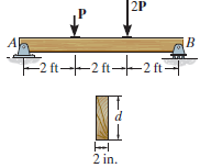
If the beam is made from wood having an allowable shear stress Ï„allow= 400 psi, determine the maximum magnitude of P. Set d = 4 in. 2P –2 ft- –2 ft- -2 ft- 2 in.
Determine the length of the cantilevered beam so that the maximum bending stress in the beam is equivalent to the maximum shear stress. |-b-
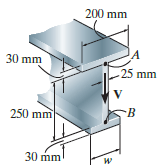
If the wide-flange beam is subjected to a shear of V = 30 kN, determine the sheer force resisted by the web of the beam. Set w = 200 mm. 200 mm LA 25 mm 30 mm 250 mm 30 mm
If the wide-flange beam is subjected to a shear of V = 30 kN, determine the maximum shear stress in the beam. Set w = 200 mm. 200 mm 30 mm 25 mm A. 250 mm 30 mm
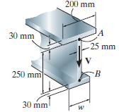
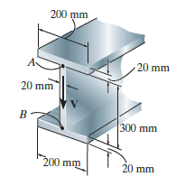
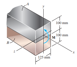
If the beam is subjected to a shear of V = 15 kN, determine the web€™s shear stress at A and B. Indicate the shear-stress components on a volume element located at these points. Set w = 125 mm. Show that the neutral axis is located at yÌ… = 0.1747 m from the bottom and INA =
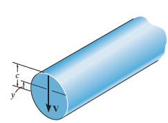
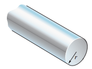
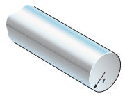
Plot the shear-stress distribution over the cross section of a rod that has a radius c. By what factor is the maximum shear stress greater than the average shear stress acting over the cross section?
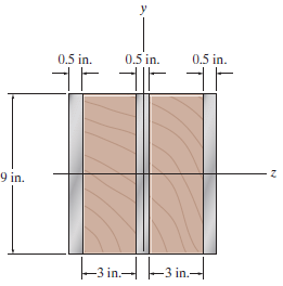
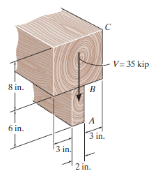
Sketch the intensity of the shear-stress distribution acting over the beam€™s cross-sectional area, and determine the resultant shear force acting on the segment AB. The sheer force acting at the section is V = 35 kip. Show that INA= 872.49 in4. V= 35 kip 8 in. 6 in. 3 in. 3 in. 2 in.
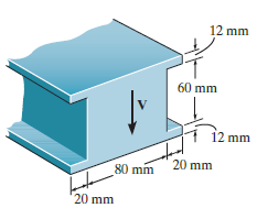
Determine the maximum shear force V that the strut can support if the allowable shear stress for the material is Ï„allow= 40 MPa. 12 mm 60 mm 12 mm 20 mm 80 mm '20 mm
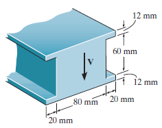
Determine the maximum shear stress in the strut if it is subjected to a sheer force of V = 20 kN. 12 mm 60 mm 12 mm 20 mm 80 mm 20 mm
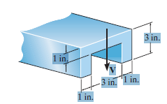
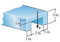
The beam is made from a polymer and is subjected to a shear of V = 7 kip. Determine the maximum shear stress in the beam and plot the shear-stress distribution over the cross section. Report the values of the shear stress every 0.5 in. of beam depth. - 4 in. 1 in. 1 in.- 6 in. in.I[ 1 in.]
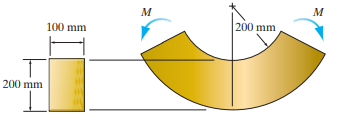
The member has a circular cross section. If the allowable bending stress is σallow= 100 MPa, determine the maximum moment M that can be applied to the member.
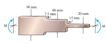
The stepped bar has a thickness of 10 mm. Determine the maximum moment that can be applied to its ends if the allowable bending stress is σallow= 150 MPa. 90 mm 60 mm 20 mm 7.5 mm 15 mm м
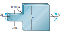
The bar has a thickness of 0.5 in. and is subjected to a moment of 600 lb # ft. Determine the maximum bending stress in the bar. 0.30 in. м 6 in. 2 in.
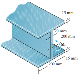
Determine the shape factor for the wide-flange beam. 15 mm 20 mm 200 mm M. 15 mm 200 mm
The beam is made of an elastic perfectly plastic material for which σY= 250 MPa. Determine the residual stress in the beam at its top and bottom after the plastic moment Mpis applied and then released. 9-
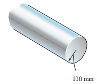
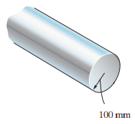
The rod has a circular cross section. If it is made of an elastic perfectly plastic material, determine the shape factor. 100 mm
The rod has a circular cross section. If it is made of an elastic perfectly plastic material where σY= 345 MPa, determine the maximum elastic moment and plastic moment that can be applied to the cross section. 100 mm
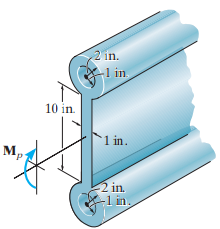
The beam is made of an elastic perfectly plastic material. Determine the plastic moment Mpthat can be supported by a beam having the cross section shown. σY= 30 ksi. 2 in. 1 in 10 in `1 in. м, 2 in 1 in.
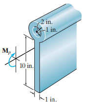
Determine the plastic moment Mpthat can be supported by a beam having the cross section shown. σY= 30 ksi. 2 in. -1 in. M, 10 in. K1 in.
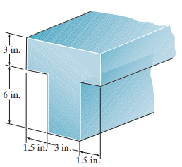
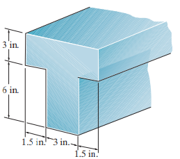
Determine the shape factor for the beam. 3 in. 6 in. 1.5 in! 3 in. 1.5 in!
The beam is made of elastic perfectly plastic material. Determine the maximum elastic moment and the plastic moment that can be applied to the cross section. Take σY= 36 ksi. 1.5 in! 3 in.. 1.5 in.
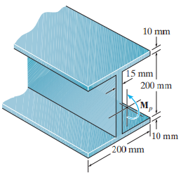
Determine the shape factor for the beam. 10 mm 15 mm 200 mm M, 10 mm 200 mm
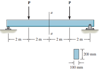
The beam is made of an elastic perfectly plastic material for which σY= 200 MPa. If the largest moment in the beam occurs within the center section a€“a, determine the magnitude of each force P that causes this moment to be (a) the largest elastic moment and (b) the largest
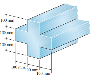
The beam is made of elastic perfectly plastic material for which σY= 345 MPa. Determine the maximum elastic moment and the plastic moment that can be applied to the cross section. 100 mm 100 mm 100 mm 100 mm 100 mm 100 mm
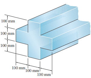
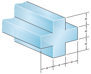
Determine the shape factor of the cross section. 100 mm 100 mm 100 mm 100 mm 100 mm 100 mm
The rod has a circular cross section. If it is made of an elastic perfectly plastic material, determine the shape factor for the rod.
The rod has a circular cross section. If it is made of an elastic perfectly plastic material, determine the maximum elastic moment and plastic moment that can be applied to the cross section. Take r = 3 in., σY= 36 ksi.
Determine the shape factor of the cross section. ーミー
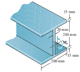
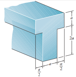
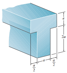
The beam is made of elastic perfectly plastic material. Determine the maximum elastic moment and the plastic moment that can be applied to the cross section. Take a = 50 mm and σY= 230 MPa. 2a
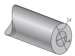
Determine the shape factor for the member having the tubular cross section. 2d
Determine the shape factor of the cross section. fototod
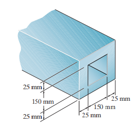
The box beam is made of an elastic perfectly plastic material for which σY= 250 MPa. Determine the residual stress in the top and bottom of the beam after the plastic moment Mpis applied and then released. 25 mm 25 mm 150 mm 150 mm 25 mm 25 mm
The beam is made of an elastic perfectly plastic material for which σY= 250 MPa. Determine the residual stress in the beam at its top and bottom after the plastic moment Mpis applied and then released. 15 mm 20 mm 200 mm M, 115 mm 200 mm
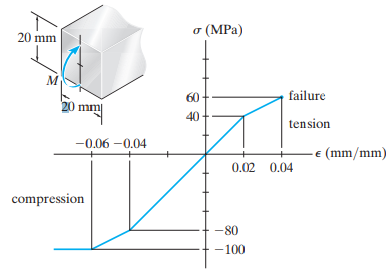
The Plexiglas bar has a stress€“strain curve that can be approximated by the straight-line segments shown. Determine the largest moment M that can be applied to the bar before it fails. (MPa) 20 mm failure 60 20 mi 40 tension -0.06 -0.04 (mm/mm) 0.02 0.04 compression -80 -100
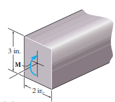
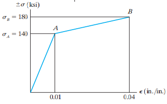
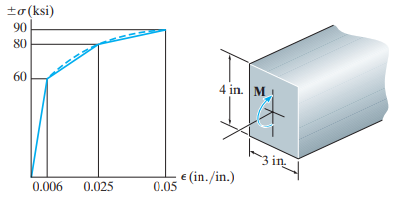
The stress€“strain diagram for a titanium alloy can be approximated by the two straight lines. If a strut made of this material is subjected to bending, determine the moment resisted by the strut if the maximum stress reaches a value of (a) σAand (b) σB. 3 in. |м. 2
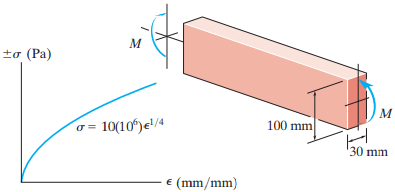
A beam is made from polypropylene plastic and has a stress€“strain diagram that can be approximated by the curve shown. If the beam is subjected to a maximum tensile and compressive strain of ε = 0.02 mm/mm, determine the moment M. м to (Pa) 100 mm 10(10ʻ)e'/4 30 mm E
The bar is made of an aluminium alloy having a stress€“strain diagram that can be approximated by the straight line segments shown. Assuming that this diagram is the same for both tension and compression, determine the moment the bar will support if the maximum strain at the top and
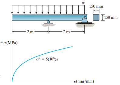
The beam is made of phenolic, a structural plastic that has the stress€“strain curve shown. If a portion of the curve can be represented by the equation σ = (5(106)ε)1/2MPa, determine the magnitude w of the distributed load that can be applied to the beam without
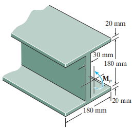
Determine the shape factor for the wide-flange beam. 20 mm 30 mm 180 mm 120 mm 180 mm
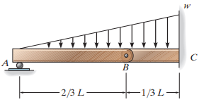
The compound beam consists of two segments that are pinned together at B. Draw the shear and moment diagrams if it supports the distributed loading shown. наи- -1/3 L- - 2/3 L-
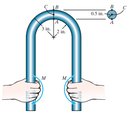
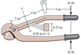
Determine the maximum bending stress in the handle of the cable cutter at section a€“a. A force of 45 lb is applied to the handles. 45 Ib 5 in. 4 in. 3 in. 0.75 in. 0.50 in. 45 lb
The composite beam consists of a wood core and two plates of steel. If the allowable bending stress for the wood is (σallow)w= 20 MPa, and for the steel (σallow)st= 130 MPa, determine the maximum moment that can be applied to the beam. Ew= 11 GPa, Est= 200 GPa. 125 mm м M 20
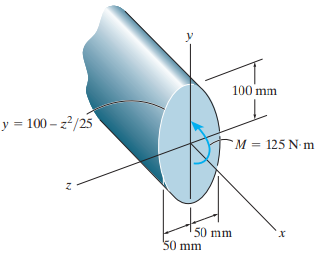
A shaft is made of a polymer having a parabolic upper and lower cross section. If it resists a moment of M = 125 N · m, determine the maximum bending stress in the material (a) using the flexure formula and (b) using integration. Sketch a three-dimensional view of the stress distribution
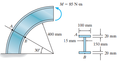
The curved beam is subjected to a bending moment of M = 85 N · m as shown. Determine the stress at points A and B and show the stress on a volume element located at these points. M = 85 N-m 100 mm A. 400 mm 20 mm 15 mm 150 mm 30° 20 mm B
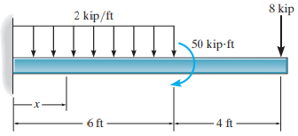
Determine the shear and moment in the beam as functions of x, where 0 ‰¤ x < 6 ft, then draw the shear and moment diagrams for the beam. 8 kip 2 kip/ft 50 kip-ft 6 ft 4 ft
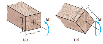
A wooden beam has a square cross section as shown. Determine which orientation of the beam provides the greatest strength at resisting the moment M. What is the difference in the resulting maximum stress in both cases? м м (a) (b)
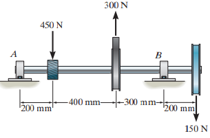
Draw the shear and moment diagrams for the shaft if it is subjected to the vertical loadings. The bearings at A and B exert only vertical reactions on the shaft. 300 N 450 N -300 mm- 400 mm- 200 mm 200 mm 150 N
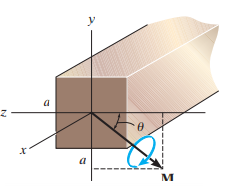
The strut has a square cross section a by a and is subjected to the bending moment M applied at an angle θ as shown. Determine the maximum bending stress in terms of a, M, and θ. What angle θ will give the largest bending stress in the strut? Specify the
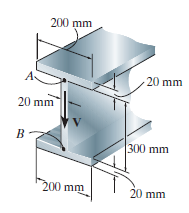
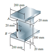
If the wide-flange beam is subjected to a shear of V = 20 kN, determine the maximum shear stress in the beam. 200 mm 20 mm 20 mm в- 300 mm 200 mm 20 mm
If the wide-flange beam is subjected to a shear of V = 20 kN, determine the shear stress on the web at A. Indicate the shear-stress components on a volume element located at this point. 200 mm 20 mm 20 mm 300 mm 200 mm 20 mm
If the wide-flange beam is subjected to a shear of V = 20 kN, determine the sheer force resisted by the web of the beam. 200 mm 20 mm 20 mm B- 300 mm 200 mm 20 mm
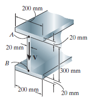
If the beam is subjected to a shear of V = 30 kN, determine the web€™s shear stress at A and B. Indicate the shear-stress components on a volume element located at these points. Set w = 200 mm. Show that the neutral axis is located at yÌ… = 0.2433 m from the bottom and I =
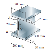
If the wide-flange beam is subjected to a shear of V = 30 kN, determine the maximum shear stress in the beam. Set w = 300 mm. 200 mm 20 mm 20 mm 300 mm 200 mm 20 mm
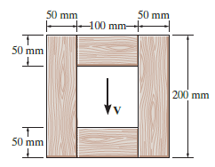
The wood beam has an allowable shear stress of Ï„ allow= 7 MPa. Determine the maximum shear force V that can be applied to the cross section. 50 mm 50 mm +100 mm- 50 mm 200 mm 50 mm
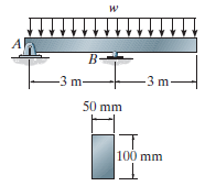
The overhang beam is subjected to the uniform distributed load having an intensity of w = 50 kN/m. Determine the maximum shear stress in the beam. B- -3 m -3 m- 50 mm 100 mm
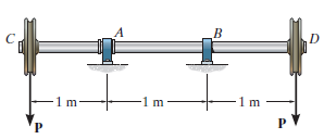
The shaft is supported by a thrust bearing at A and a journal bearing at B. If P = 20 kN, determine the absolute maximum shear stress in the shaft. A -1m -1m-
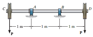
The shaft is supported by a thrust bearing at A and a journal bearing at B. If the shaft is made from a material having an allowable shear stress of Ï„allow= 75 MPa, determine the maximum value for P. D -1 m 1m- P.
Determine the largest shear force V that the member can sustain if the allowable shear stress is Ï„allow= 8 ksi. 3 in. 1 in, -3 in. 1 in. 1 in.
If the applied shear force V = 18 kip, determine the maximum shear stress in the member. 3 in. 1 in. in. '1 in. 1 in.
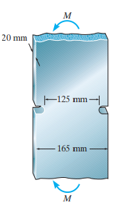
If the radius of each notch on the plate is r = 10 mm, determine the largest moment M that can be applied. The allowable bending stress is σallow= 180 MPa. 20 mm 125 mm- 165 mm
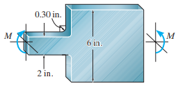
The bar has a thickness of 0.5 in. and the allowable bending stress is σallow= 20 ksi. Determine the maximum moment M that can be applied. 0.30 in. 6 in. 2 in.
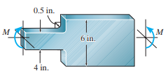
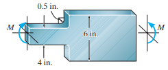
The bar has a thickness of 1 in. and is subjected to a moment of 3 kip · ft. Determine the maximum bending stress in the bar. 0.5 in. м 6 in. 4 in.
The bar has a thickness of 1 in. and the allowable bending stress is σallow= 30 ksi. Determine the maximum moment M that can be applied. 0.5 in. 6 in. 4 in.
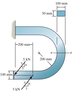
The curved bar used on a machine has a rectangular cross section. If the bar is subjected to a couple as shown, determine the maximum tensile and compressive stress acting at section a€“a. Sketch the stress distribution on the section in three dimensions. 100 mm 50 mm -200 mm- 5 kN 200 mm
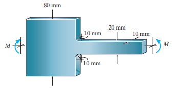
The bar is subjected to a moment of M = 100 N # m. Determine the maximum bending stress in the bar and sketch, approximately, how the stress varies over the critical section. 80 mm 20 mm 10 mm 10 mm 10 mm
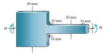
The allowable bending stress for the bar is σallow= 200 MPa. Determine the maximum moment M that can be applied to the bar. 80 mm 20 mm 10 mm 10 mm 10 mm
The composite beam is made of A-36 steel (A) bonded to C83400 red brass (B) and has the cross section shown. If it is subjected to a moment of M = 6.5 kN · m, determine the maximum stress in the brass and steel. Also, what is the stress in each material at the seam where they are bonded
The composite beam is made of A-36 steel (A) bonded to C83400 red brass (B) and has the cross section shown. If the allowable bending stress for the steel is (σallow)st= 180 MPa and for the brass (σallow)br= 60 MPa, determine the maximum moment M that can be applied to the
If the beam is subjected to a moment of M = 45 kN · m, determine the maximum bending stress in the A-36 steel section A and the 2014-T6 aluminum alloy section B. 50 mm м 15 mm 150 mm
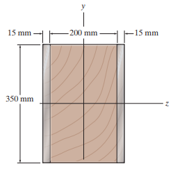
The Douglas Fir beam is reinforced with A-36 steel straps at its sides. Determine the maximum stress in the wood and steel if the beam is subjected to a bending moment of Mz= 4 kN · m. Sketch the stress distribution acting over the cross section. -200 mm- 15 mm -15 mm 350 mm
For the curved beam in Fig. 6–40a, show that when the radius of curvature approaches infinity, the curved-beam formula, Eq. 6–24, reduces to the flexure formula, Eq. 6–13.
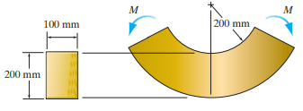
The curved member is subjected to the moment of M = 50 kN · m. Determine the percentage error introduced in the calculation of maximum bending stress using the flexure formula for straight members. м м 200 mm 100 mm 200 mm
The curved member is made from material having an allowable bending stress of σallow= 100 MPa. Determine the maximum allowable moment M that can be applied to the member. 200 mm 100 mm 200 mm
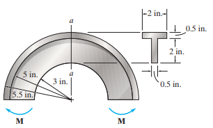
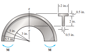
The curved beam is subjected to a moment of M = 40 lb · ft. Determine the maximum bending stress in the beam. Also, sketch a two-dimensional view of the stress distribution acting on section a€“a. -2 in.- I0.5 in. 2 in. 5 in. 3 in. 0.5 in. 5.5 in. M м
The curved beam is made from material having an allowable bending stress of σallow= 24 ksi. Determine the maximum moment M that can be applied to the beam. -2 in.- 0.5 in. 2 in. 5 in. '0.5 in. 3 in. 5.5 in. м
If P = 3 kN, determine the bending stress at points A, B, and C of the cross section at section a€“a. Using these results, sketch the stress distribution on section a€“a.
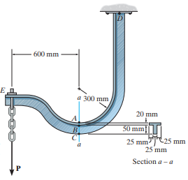
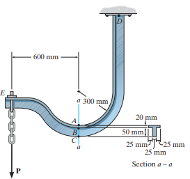
If the maximum bending stress at section a€“a is not allowed to exceed sallow = 150 MPa, determine the maximum allowable force P that can be applied to the end E. 600 mm a 300 mm 20 mm 50 mm|| 25 mmT)25 mm 25 mm B. Section a -a
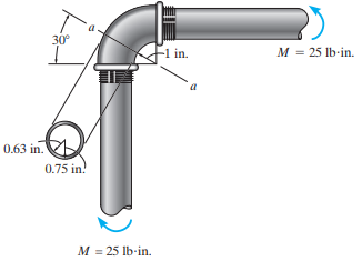
The elbow of the pipe has an outer radius of 0.75 in. and an inner radius of 0.63 in. If the assembly is subjected to the moments of M = 25 lb · in., determine the maximum stress at section a€“a. 30° M = 25 lb-in. -1 in. 0.63 in. 0.75 in! M = 25 lb-in.
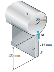
The curved bar used on a machine has a rectangular cross section. If the bar is subjected to a couple as shown, determine the maximum tensile and compressive stresses acting at section a€“a. Sketch the stress distribution on the section in three dimensions. 10 kN 30 150 mm 30° 150 mm 10
The curved bar used on a machine has a rectangular cross section. If the bar is subjected to a couple as shown, determine the maximum tensile and compressive stresses acting at section a€“a. Sketch the stress distribution on the section in three dimensions. 75 mm 50 mm 100 mm 50 mm 250 N
The steel rod has a circular cross section. If it is gripped at its ends and a couple moment of M = 12 lb · in is developed at each grip, determine the stress acting at points A and B and at the centroid C. с 1в 0.5 in.- 3 in. 2 in. м м
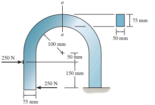
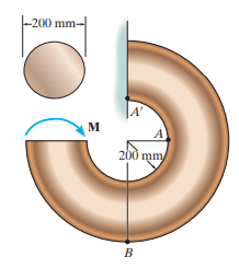
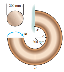
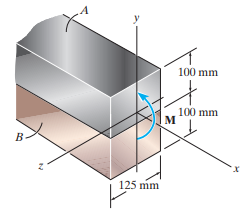
The member has a circular cross section. If it is subjected to a moment of M = 5 kN · m, determine the stress at points A and B. Is the stress at point A€², which is located on the member near the wall, the same as that at A? Explain. -200 mm- A' м 200 mm B.
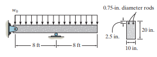
Determine the maximum uniform distributed load w0 that can be supported by the reinforced concrete beam if the allowable tensile stress for the steel is (σst)allow= 28 ksi and the allowable compressive stress for the concrete is (σconc)allow= 3 ksi. Assume the concrete cannot
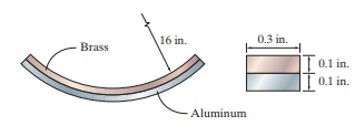
A bimetallic strip is made from pieces of 2014-T6 aluminum and C83400 red brass, having the cross section shown. A temperature increase causes its neutral surface to be bent into a circular arc having a radius of 16 in. Determine the moment that must be acting on its cross section due to the
A wood beam is reinforced with steel straps at its top and bottom as shown. Determine the maximum bending stress developed in the wood and steel if the beam is subjected to a moment of M = 150 kN · m. Sketch the stress distribution acting over the cross section. Take Ew= 10 GPa,
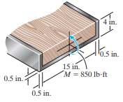
The steel channel is used to reinforce the wood beam. Determine the maximum stress in the steel and in the wood if the beam is subjected to a moment of M = 850 lb · ft. Est= 29(103) ksi, Ew= 1600 ksi. 4 in. 0.5 in. 15 in. M = 850 lb-ft 0.5 in. 0.5 in.
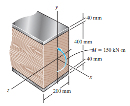
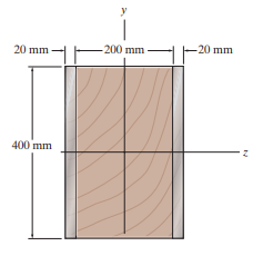
The Douglas Fir beam is reinforced with A-992 steel straps at its sides. Determine the maximum stress in the wood and steel if the beam is subjected to a moment of Mz= 80 kN · m. Sketch the stress distribution acting over the cross section. 20 mm -200 mm -20 mm 400 mm
The wooden section of the beam is reinforced with two steel plates as shown. If the beam is subjected to a moment of M = 30 kN · m, determine the maximum bending stresses in the steel and wood. Sketch the stress distribution over the cross section. Take Ew= 10 GPa and Est= 200 GPa. 15 mm 150
The wooden section of the beam is reinforced with two steel plates as shown. Determine the maximum moment M that the beam can support if the allowable stresses for the wood and steel are (σallow)w= 6 MPa, and (σallow)st= 150 MPa, respectively. Take Ew= 10 GPa and Est= 200 GPa.
The white spruce beam is reinforced with A-992 steel straps at its center and sides. Determine the maximum stress developed in the wood and steel if the beam is subjected to a bending moment of Mz= 10 kip ˆ™ ft. Sketch the stress distribution acting over the cross section. 0,5 in. 0.5 in.
Showing 300 - 400
of 983
1
2
3
4
5
6
7
8
9
10
Step by Step Answers
![- 4 in. 1 in. 1 in.- 6 in. in.I[ 1 in.]](https://dsd5zvtm8ll6.cloudfront.net/si.question.images/images/question_images/1527/2/2/5/3205b079be8186461527225322465.jpg)
![10 kN 30 150 mm 30° 150 mm 10 kN 200 mm 100 mm mm] 100 mm](https://dsd5zvtm8ll6.cloudfront.net/si.question.images/images/question_images/1527/1/5/6/0795b068d6f192411527156079932.jpg)