New Semester
Started
Get
50% OFF
Study Help!
--h --m --s
Claim Now
Question Answers
Textbooks
Find textbooks, questions and answers
Oops, something went wrong!
Change your search query and then try again
S
Books
FREE
Study Help
Expert Questions
Accounting
General Management
Mathematics
Finance
Organizational Behaviour
Law
Physics
Operating System
Management Leadership
Sociology
Programming
Marketing
Database
Computer Network
Economics
Textbooks Solutions
Accounting
Managerial Accounting
Management Leadership
Cost Accounting
Statistics
Business Law
Corporate Finance
Finance
Economics
Auditing
Tutors
Online Tutors
Find a Tutor
Hire a Tutor
Become a Tutor
AI Tutor
AI Study Planner
NEW
Sell Books
Search
Search
Sign In
Register
study help
sciences
mechanics of materials
Mechanics Of Materials 10th Edition Russell C. Hibbeler - Solutions
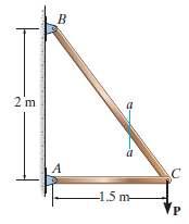
Determine the largest load P that can be applied to the frame without causing either the average normal stress or the average shear stress at section a€“a to exceed σ = 150 MPa and Ï„ = 60 MPa, respectively. Member CB has a square cross section of 25 mm on each side.
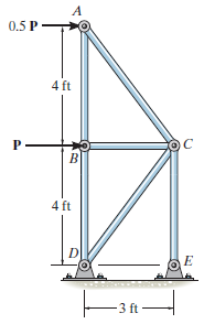
The bars of the truss each have a cross-sectional area of 1.25 in2. Determine the average normal stress in members AB, BD, and CE due to the loading P = 6 kip. State whether the stress is tensile or compressive. A 0.5 P- 4 ft 4 ft 3 ft
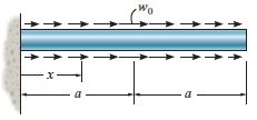
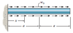
The prismatic bar has a cross-sectional area A. If it is subjected to a distributed axial loading that increases linearly from w = 0 at x = 0 to w = w0at x = a, and then decreases linearly to w = 0 at x = 2a, determine the average normal stress in the bar as a function of x for a < x
The prismatic bar has a cross-sectional area A. If it is subjected to a distributed axial loading that increases linearly from w = 0 at x = 0 to w = w0at x = a, and then decreases linearly to w = 0 at x = 2a, determine the average normal stress in the bar as a function of x for 0 ‰¤ x
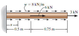
The bar has a cross-sectional area of 400(10ˆ’6) m2. If it is subjected to a uniform axial distributed loading along its length and to two concentrated loads, determine the average normal stress in the bar as a function of x for 0.5 m < x ‰¤ 1.25 m. w = 8 kN/m -6 kN 3 kN
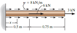
The bar has a cross-sectional area of 400(10ˆ’6) m2. If it is subjected to a uniform axial distributed loading along its length and to two concentrated loads, determine the average normal stress in the bar as a function of x for 0 < x ‰¤ 0.5 m. w = 8 kN/m -6 kN 3 kN 0.75 m-
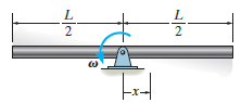
The uniform bar, having a cross-sectional area of A and mass per unit length of m, is pinned at its center. If it is rotating in the horizontal plane at a constant angular rate of ω, determine the average normal stress in the bar as a function of x. -늘-
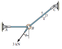
Rods AB and BC have diameters of 4 mm and 6 mm, respectively. If the 3 kN force is applied to the ring at B, determine the angle θ so that the average normal stress in each rod is equivalent. What is this stress? FA 3 kN
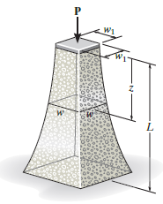
The pier is made of material having a specific weight g. If it has a square cross section, determine its width w as a function of z so that the average normal stress in the pier remains constant. The pier supports a constant load P at its top where its width is w1. W1 и
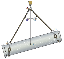
The 2-Mg concrete pipe has a center of mass at point G. If it is suspended from cables AB and AC, determine the diameter of cable AB so that the average normal stress in this cable is the same as in the 10-mm-diameter cable AC. 30 45° Be
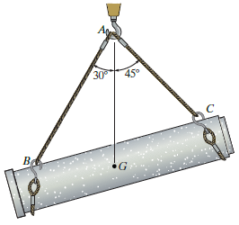
The 2-Mg concrete pipe has a center of mass at point G. If it is suspended from cables AB and AC, determine the average normal stress in the cables. The diameters of AB and AC are 12 mm and 10 mm, respectively. 30° 45°
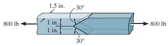
The two members used in the construction of an aircraft fuselage are joined together using a 30° fish-mouth weld. Determine the average normal and average shear stress on the plane of each weld. Assume each inclined plane supports a horizontal force of 400 lb. 1.5 in. 30° 1 in. 1 in. 800 lb
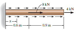
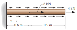
The bar has a cross-sectional area of 400(10ˆ’6) m2. If it is subjected to a uniform axial distributed loading along its length of 9 kN/m, and to two concentrated loads as shown, determine the average normal stress in the bar as a function of x for 0.6 m < x ‰¤ 1.5 m. -8 kN
The bar has a cross-sectional area of 400(10ˆ’6) m2. If it is subjected to a triangular axial distributed loading along its length which is 0 at x = 0 and 9 kN/m at x = 1.5 m, and to two concentrated loads as shown, determine the average normal stress in the bar as a function of x for 0
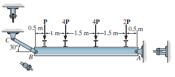
If P = 15 kN, determine the average shear stress in the pins at A, B, and C. All pins are in double shear, and each has a diameter of 18 mm. 4P 4P 2P 0.5 m 0.5,m -1.5 m -1 m--1.5 m 307
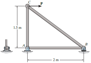
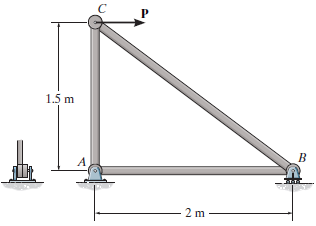
If the average normal stress in each of the 20-mm-diameter bars is not allowed to exceed 150 MPa, determine the maximum force P that can be applied to joint C. 1.5 m 2 m –
Determine the average normal stress in each of the 20-mm-diameter bars of the truss. Set P = 40 kN. 1.5 m 2 m
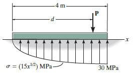
The plate has a width of 0.5 m. If the stress distribution at the support varies as shown, determine the force P applied to the plate and the distance d to where it is applied. 4 m- (15x2) MPa- 30 MPa
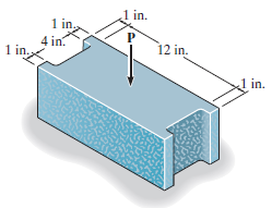
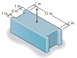
If the block is subjected to a centrally applied force of P = 6 kip, determine the average normal stress in the material. Show the stress acting on a differential volume element of the material. 1 in. 1 in ., 4 in. 12 in. 1 in. 1 in.
If the material fails when the average normal stress reaches 120 psi, determine the largest centrally applied vertical load P the block can support. 1 in. 1 in 4 in. 1 in. 12 in. in.
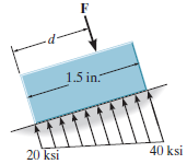
The small block has a thickness of 0.5 in. If the stress distribution at the support developed by the load varies as shown, determine the force F applied to the block, and the distance d to where it is applied. -p- 1.5 in. 40 ksi 20 ksi
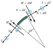
A differential element taken from a curved bar is shown in the figure. Show that dN/dθ = V, dV/dθ = €“ N, dM/dθ = €“T, and dT/dθ = M. M + dM T + dT V + dV, N + dN M.
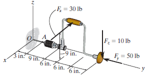
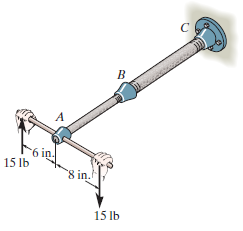
The brace and drill bit is used to drill a hole at O. If the drill bit jams when the brace is subjected to the forces shown, determine the resultant internal loadings acting on the cross section of the drill bit at A. F = 30 lb F = 10 lb C9 in. F = 50 lb in? 9 in. 6 in. 6 in.
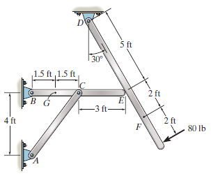
Determine the resultant internal loadings acting on the cross section of the frame at points F and G. The contact at E is smooth. 5 ft 30° 1.5 ft ,1.5 ft 2 ft B. -3 ft- 2 ft 80 lb 4 ft
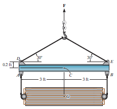
Determine the resultant internal loadings acting on the cross section at point C. The cooling unit has a total weight of 52 kip and a center of gravity at G. 0.2 f в - 3 ft- - 3A- 3ft
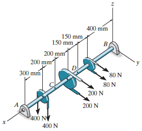
The shaft is supported at its ends by two bearings A and B and is subjected to the forces applied to the pulleys fixed to the shaft. Determine the resultant internal loadings acting on the cross section at point D. The 400-N forces act in the -z direction and the 200-N and 80-N forces act in the +y
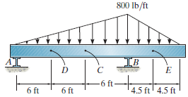
The beam supports the distributed load shown. Determine the resultant internal loadings on the cross section at points D and E. Assume the reactions at the supports A and B are vertical. 800 lb/ft IB -6 ft- 6 ft 4.5 ft' 4.5 ft 6 ft
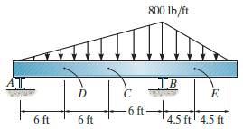
The beam supports the triangular distributed load shown. Determine the resultant internal loadings on the cross section at point C. Assume the reactions at the supports A and B are vertical. 800 Ib/ft IB 6 ft- 4.5 ft' 4.5 ft 6 ft 6 ft
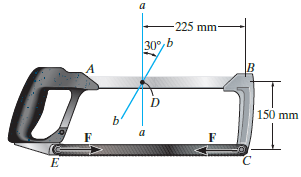
The blade of the hacksaw is subjected to a pretension force of F = 100 N. Determine the resultant internal loadings acting on section b€“b that passes through point D. 225 mm- 30°, b 150 mm
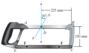
The blade of the hacksaw is subjected to a pretension force of F = 100 N. Determine the resultant internal loadings acting on section a€“a that passes through point D. -225 mm 30%,Ь D 150 mm
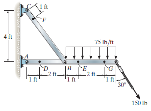
Determine the resultant internal loadings acting on the cross sections at points F and G of the frame. 4 ft 75 Ib/ft B. -2 ft 1 ft -2 ft 1 ft 30° '1 ft 150 lb to
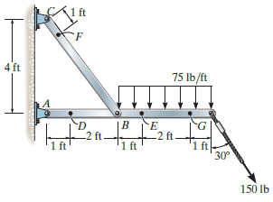
Determine the resultant internal loadings acting on the cross sections at points D and E of the frame. 4 ft 75 Ib/ft LA B. 2 ft 2 ft 1 ft 1 ft 30° 1 ft 150 lb
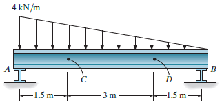
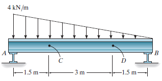
The beam supports the distributed load shown. Determine the resultant internal loadings acting on the cross section at point D. Assume the reactions at the supports A and B are vertical. 4 kN/m -1.5 m–| -1.5 m- 3 m
The beam supports the distributed load shown. Determine the resultant internal loadings acting on the cross section at point C. Assume the reactions at the supports A and B are vertical. 4 kN/m A -1.5 m. -1.5 m- 3 m
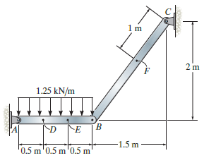
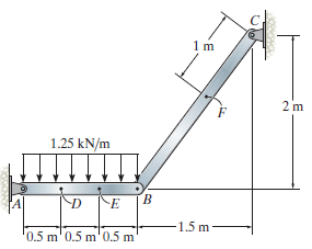
Determine the resultant internal loadings at cross sections at points E and F on the assembly. 1.25 kN/m 1.5 m '0.5 m'0.5 m'0.5 m
Determine the resultant internal loadings on the cross section at point D. 1.25 kN/m 1.5 m '0.5 m' 0.5 m'0.5 m
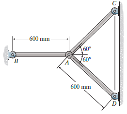
The rods each have the same 25-mm diameter and 600-mm length. If they are made of A992 steel, determine the forces developed in each rod when the temperature increases by 50° C. -600 mm 60° /60° 600 mm
Two A992 steel pipes, each having a cross-sectional area of 0.32 in2, are screwed together using a union at B. Originally the assembly is adjusted so that no load is on the pipe. If the union is then tightened so that its screw, having a lead of 0.15 in., undergoes two full turns, determine the
The force P is applied to the bar, which is made from an elastic perfectly plastic material. Construct a graph to show how the force in each section AB and BC (vertical axis) varies as P (horizontal axis) is increased. The bar has cross-sectional areas of 1 in2in region AB and 4 in2in region BC.
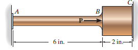
The 2014-T6 aluminum rod has a diameter of 0.5 in. and is lightly attached to the rigid supports at A and B when T1= 70°F. If the temperature becomes T2= €“ 10°F, and an axial force of P = 16 lb is applied to the rigid collar as shown, determine the reactions at the rigid supports
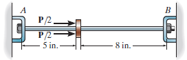
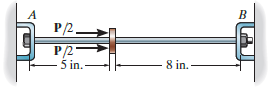
The 2014-T6 aluminum rod has a diameter of 0.5 in. and is lightly attached to the rigid supports at A and B when T1= 70°F. Determine the force P that must be applied to the collar so that, when T = 0°F, the reaction at B is zero. A B P/2_ P/2 -5 in.- 8 in. -
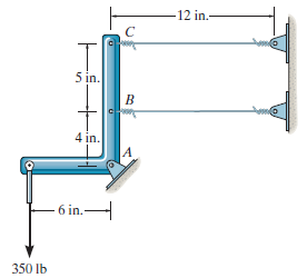
The rigid link is supported by a pin at A and two A-36 steel wires, each having an unstretched length of 12 in. and cross-sectional area of 0.0125 in2. Determine the force developed in the wires when the link supports the vertical load of 350 lb. 12 in.- 5 in. 4 in. - 6 in. 350 Ib
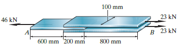
The joint is made from three A992 steel plates that are bonded together at their seams. Determine the displacement of end A with respect to end B when the joint is subjected to the axial loads. Each plate has a thickness of 5 mm. 100 mm 23 kN 46 kN B 23 kN 800 mm 600 mm 200 mm
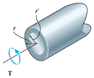
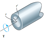
The solid shaft of radius r is subjected to a torque T. Determine the radius r of the inner core of the shaft that resists one-half of the applied torque (T>2). Solve the problem two ways: (a) by using the torsion formula, (b) by finding the resultant of the shear-stress distribution. T
The solid shaft of radius r is subjected to a torque T. Determine the radius r' of the inner core of the shaft that resists one-quarter of the applied torque (T/4). Solve the problem two ways:(a) By using the torsion formula,(b) By finding the resultant of the shear-stress distribution. т
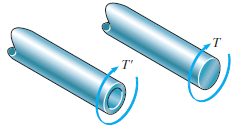
A shaft is made of an aluminum alloy having an allowable shear stress of Ï„allow= 100 MPa. If the diameter of the shaft is 100 mm, determine the maximum torque T that can be transmitted. What would be the maximum torque T' if a 75-mm-diameter hole were bored through the shaft? Sketch
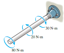
The copper pipe has an outer diameter of 40 mm and an inner diameter of 37 mm. If it is tightly secured to the wall and three torques are applied to it, determine the absolute maximum shear stress developed in the pipe. 30 N-m 20 N-m 80 N-m
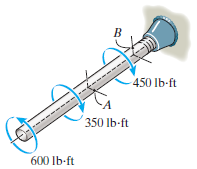
The copper pipe has an outer diameter of 2.50 in. and an inner diameter of 2.30 in. If it is tightly secured to the wall and three torques are applied to it, determine the shear stress developed at points A and B. These points lie on the pipe€™s outer surface. Sketch the shear stress on
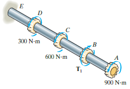
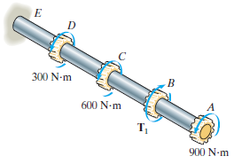
The solid aluminum shaft has a diameter of 50 mm and an allowable shear stress of Ï„allow= 60 MPa. Determine the largest torque T1that can be applied to the shaft if it is also subjected to the other torsional loadings. It is required that T1act in the direction shown. Also, determine the
The solid aluminum shaft has a diameter of 50 mm. Determine the absolute maximum shear stress in the shaft and sketch the shear-stress distribution along a radial line of the shaft where the shear stress is maximum. Set T1= 2000 N ˆ™ m. 300 N-m 600 N-m т, 900 N-m
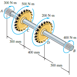
The solid 30-mm-diameter shaft is used to transmit the torques applied to the gears. Determine the absolute maximum shear stress in the shaft. 300 N-m 500 N-m 200 N-m 400 N-m 300 mm B. 400 mm 500 mm
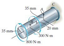
The solid shaft is fixed to the support at C and subjected to the torsional loadings. Determine the shear stress at points A and B on the surface, and sketch the shear stress on volume elements located at these points. 35 mm A 20 mm 35 mm- 300 N-m 800 N-m
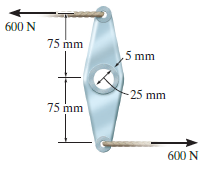
The link acts as part of the elevator control for a small airplane. If the attached aluminum tube has an inner diameter of 25 mm and a wall thickness of 5 mm, determine the maximum shear stress in the tube when the cable force of 600 N is applied to the cables. Also, sketch the shear-stress
The assembly consists of two sections of galvanized steel pipe connected together using a reducing coupling at B. The smaller pipe has an outer diameter of 0.75 in. and an inner diameter of 0.68 in., whereas the larger pipe has an outer diameter of 1 in. and an inner diameter of 0.86 in. If the
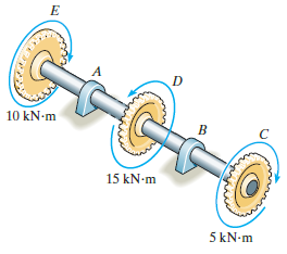
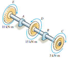
The shaft has an outer diameter of 100 mm and an inner diameter of 80 mm. If it is subjected to the three torques, determine the absolute maximum shear stress in the shaft. The smooth bearings A and B do not resist torque. 10 kN-m 15 kN-m 5 kN-m
The shaft has an outer diameter of 100 mm and an inner diameter of 80 mm. If it is subjected to the three torques, plot the shear stress distribution along a radial line for the cross section within region CD of the shaft. The smooth bearings at A and B do not resist torque. 10 kN-m 15 kN-m 5 kN-m
A steel tube having an outer diameter of 2.5 in. is used to transmit 9 hp when turning at 27 rev/min. Determine the inner diameter d of the tube to the nearest 18 in. if the allowable shear stress is Ï„allow= 10 ksi. 2.5 in.
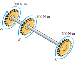
If the gears are subjected to the torques shown, determine the maximum shear stress in the segments AB and BC of the A-36 steel shaft. The shaft has a diameter of 40 mm. 300 N-m 100 N-m 200 N-m
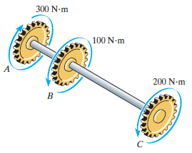
If the gears are subjected to the torques shown, determine the required diameter of the A-36 steel shaft to the nearest mm if Ï„allow= 60 MPa. 300 N-m 100 N-m 200 N-m
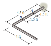
The rod has a diameter of 1 in. and a weight of 10 lb/ft. Determine the maximum torsional stress in the rod at a section located at A due to the rod€™s weight. 4.5 ft 1.5 ft 1.5 ft B. 4 ft
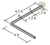
The rod has a diameter of 1 in. and a weight of 15 lb/ft. Determine the maximum torsional stress in the rod at a section located at B due to the rod€™s weight. 4.5 ft -1.5 ft 1.5t B. 1.5 ft 4 ft
The copper pipe has an outer diameter of 3 in. and an inner diameter of 2.5 in. If it is tightly secured to the wall at C and a uniformly distributed torque is applied to it as shown, determine the shear stress at points A and B. These points lie on the pipe€™s outer surface. Sketch the
The copper pipe has an outer diameter of 3 in. and an inner diameter of 2.50 in. If it is tightly secured to the wall at C and it is subjected to the uniformly distributed torque along its entire length, determine the absolute maximum shear stress in the pipe. Discuss the validity of this result.
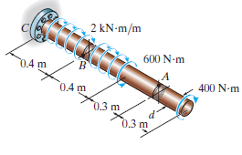
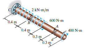
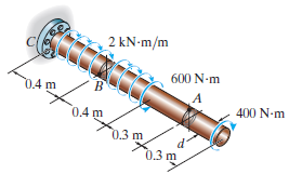
The 60-mm-diameter solid shaft is subjected to the distributed and concentrated torsional loadings shown. Determine the shear stress at points A and B, and sketch the shear stress on volume elements located at these points. 2 kN-m/m 600 N-m 04 m B. 400 N-m 0,4 m 0.3 m d' 0.3 m
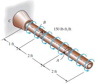
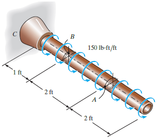
The 60-mm-diameter solid shaft is subjected to the distributed and concentrated torsional loadings shown. Determine the absolute maximum and minimum shear stresses on the shaft€™s surface, and specify their locations, measured from the fixed end C. 2 kN-m/m 600 N-m 0.4 m 400 N-m 0.4m 0.3
The solid shaft is subjected to the distributed and concentrated torsional loadings shown. Determine the required diameter d of the shaft if the allowable shear stress for the material is Ï„allow= 1.6 MPa. 2 kN-m/m 600 N-m 0.4 m 400 N-m 0.4 m 0.3 m 0.3 m
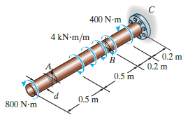
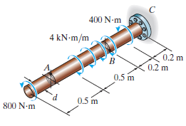
The 60-mm-diameter solid shaft is subjected to the distributed and concentrated torsional loadings shown. Determine the absolute maximum and minimum shear stresses on the shaft's surface and specify their locations, measured from the free end. 400 N-m 4 kN-m/m 0.2 m 0.2 m 0.5 m P. 0.5 m 800 N-m
The solid shaft is subjected to the distributed and concentrated torsional loadings shown. Determine the required diameter d of the shaft if the allowable shear stress for the material is Ï„allow= 60 MPa. 400 N-m 4 kN-m/m 0.2 m 0.2 m 0.5 m 0.5 m 800 N-m
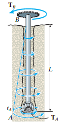
When drilling a well at constant angular velocity, the bottom end of the drill pipe encounters a torsional resistance TA. Also, soil along the sides of the pipe creates a distributed frictional torque along its length, varying uniformly from zero at the surface B to tAat A. Determine the minimum
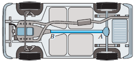
The drive shaft AB of an automobile is made of a steel having an allowable shear stress of Ï„allow= 8 ksi. If the outer diameter of the shaft is 2.5 in. and the engine delivers 200 hp to the shaft when it is turning at 1140 rev>min, determine the minimum required thickness of the
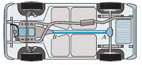
The drive shaft AB of an automobile is to be designed as a thin-walled tube. The engine delivers 150 hp when the shaft is turning at 1000 rev>min. Determine the minimum thickness of the shaft€™s wall if the shaft€™s outer diameter is 2.5 in. The material has an allowable
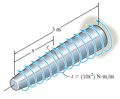
The shaft is subjected to a distributed torque along its length of t = (10x2) N ˆ™ m/m, where x is in meters. If the maximum stress in the shaft is to remain constant at 80 MPa, determine the required variation of the radius c of the shaft for 0 ‰¤ x ‰¤ 3 m. =
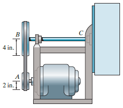
The motor delivers 50 hp while turning at a constant rate of 1350 rpm at A. Using the belt and pulley system this loading is delivered to the steel blower shaft BC. Determine to the nearest 1/8 in. the smallest diameter of this shaft if the allowable shear stress for steel is Ï„allow= 12 ksi. 4
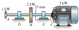
The solid steel shaft AC has a diameter of 25 mm and is supported by smooth bearings at D and E. It is coupled to a motor at C, which delivers 3 kW of power to the shaft while it is turning at 50 rev>s. If gears A and B remove 1 kW and 2 kW, respectively, determine the maximum shear stress in
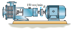
The pump operates using the motor that has a power of 85 W. If the impeller at B is turning at 150 rev/min, determine the maximum shear stress in the 20-mm-diameter transmission shaft at A. 150 rev/min R
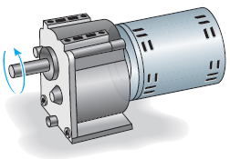
The gear motor can develop 1/10 hp when it turns at 300 rev/min. If the shaft has a diameter of 1/2 in., determine the maximum shear stress in the shaft. ニ川 ニ川
The gear motor can develop 1/10 hp when it turns at 80 rev/min. If the allowable shear stress for the shaft is Ï„allow= 4 ksi, determine the smallest diameter of the shaft to the nearest 1/8 in. that can be used. ミミ
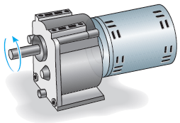
The gear motor can develop 1/4 hp when it turns at 600 rev/min. If the shaft has a diameter of 1/2 in., determine the maximum shear stress in the shaft.
The gear motor can develop 2 hp when it turns at 150 rev/min. If the allowable shear stress for the shaft is Ï„allow= 8 ksi, determine the smallest diameter of the shaft to the nearest 1/8 in. that can be used.
The 6-hp reducer motor can turn at 1200 rev/min. If the allowable shear stress for the shaft is Ï„allow= 6 ksi, determine the smallest diameter of the shaft to the nearest 1/16 in. that can be used.
The 6-hp reducer motor can turn at 1200 rev/min. If the shaft has a diameter of 5/8 in., determine the maximum shear stress in the shaft.
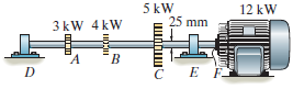
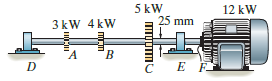
The solid steel shaft DF has a diameter of 25 mm and is supported by smooth bearings at D and E. It is coupled to a motor at F, which delivers 12 kW of power to the shaft while it is turning at 50 rev/s. If gears A, B, and C remove 3 kW, 4 kW, and 5 kW respectively, determine the maximum shear
The solid steel shaft DF has a diameter of 25 mm and is supported by smooth bearings at D and E. It is coupled to a motor at F, which delivers 12 kW of power to the shaft while it is turning at 50 rev/s. If gears A, B, and C remove 3 kW, 4 kW, and 5 kW respectively, determine the absolute maximum
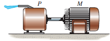
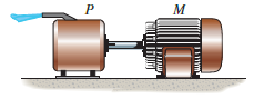
The A-36 steel tubular shaft is 2 m long and has an outer diameter of 50 mm. When it is rotating at 40 rad/s, it transmits 25 kW of power from the motor M to the pump P. Determine the smallest thickness of the tube if the allowable shear stress is Ï„allow= 80 MPa. P M
The A-36 solid steel shaft is 2 m long and has a diameter of 60 mm. It is required to transmit 60 kW of power from the moor M to the pump P. Determine the smallest angular velocity the shaft if the allowable shear stress is Ï„allow= 80 MPa. P M
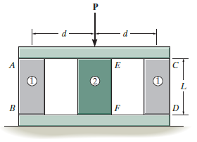
The assembly consists of two posts AB and CD each made from material 1 having a modulus of elasticity of E1and a cross-sectional area A1, and a central post EF made from material 2 having a modulus of elasticity E2and a crosssectional area A2. If post EF is to be replaced by one having a material
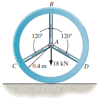
The wheel is subjected to a force of 18 kN from the axle. Determine the force in each of the three spokes. Assume the rim is rigid and the spokes are made of the same material, and each has the same cross-sectional area. 120° 120° 18 kN 0.4 m D.
The C83400-red-brass rod AB and 2014-T6- aluminum rod BC are joined at the collar B and fixed connected at their ends. If there is no load in the members when T1= 50°F, determine the average normal stress in each member when T2= 120°F. Also, how far will the collar be displaced? The
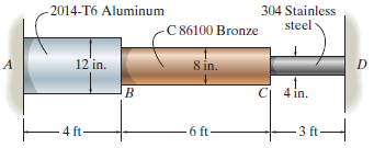
The assembly has the diameters and material indicated. If it fits securely between its fixed supports when the temperature is T1= 70°F, determine the average normal stress in each material when the temperature reaches T2= 110°F. - 2014-T6 Aluminum 304 Stainless steel C 86100 Bronze 12'in. 8
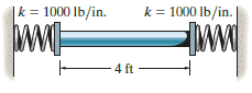
The rod is made of A992 steel and has a diameter of 0.25 in. If the rod is 4 ft long when the springs are compressed 0.5 in. and the temperature of the rod is T = 40°F, determine the force in the rod when its temperature is T = 160°F. |k = 1000 lb/in. k = 1000 lb/in. wwE 4 ft
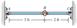
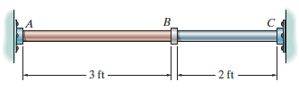
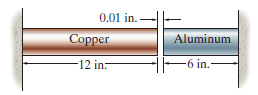
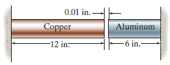
The two cylindrical rod segments are fixed to the rigid walls such that there is a gap of 0.01 in. between them when T1= 60°F. What larger temperature T2is required in order to just close the gap? Each rod has a diameter of 1.25 in. Determine the average normal stress in each rod if T2=
The two cylindrical rod segments are fixed to the rigid walls such that there is a gap of 0.01 in. between them when T1= 60°F. Each rod has a diameter of 1.25 in. Determine the average normal stress in each rod if T2= 400°F, and also calculate the new length of the aluminum segment. Take
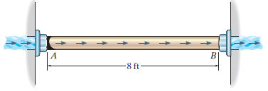
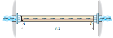
The pipe is made of A992 steel and is connected to the collars at A and B. When the temperature is 60°F, there is no axial load in the pipe. If hot gas traveling through the pipe causes its temperature to rise by ΔT = (40 + 15x)°F, where x is in feet, determine the average
The bronze C86100 pipe has an inner radius of 0.5 in. and a wall thickness of 0.2 in. If the gas flowing through it changes the temperature of the pipe uniformly from TA= 200€‘F at A to TB= 60°F at B, determine the axial force it exerts on the walls. The pipe was fitted between the
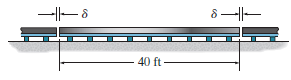
The 40-ft-long A-36 steel rails on a train track are laid with a small gap between them to allow for thermal expansion. Determine the required gap d so that the rails just touch one another when the temperature is increased from T1= €“20°F to T2= 90°F. Using this gap, what would
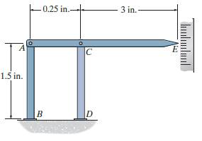
The device is used to measure a change in temperature. Bars AB and CD are made of A-36 steel and 2014-T6 aluminum alloy, respectively. When the temperature is at 75°F, ACE is in the horizontal position. Determine the vertical displacement of the pointer at E when the temperature rises to
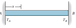
The bar has a cross-sectional area A, length L, modulus of elasticity E, and coefficient of thermal expansion a. The temperature of the bar changes uniformly along its length from TAat A to TBat B so that at any point x along the bar T = TA+ x(TB€“ TA)/L. Determine the force the bar
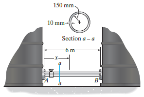
When the temperature is at 30°C, the A-36 steel pipe fits snugly between the two fuel tanks. When fuel flows through the pipe, the temperatures at ends A and B rise to 130°C and 80°C, respectively. If the temperature drop along the pipe is linear, determine the average normal stress
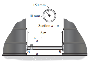
When the temperature is at 30°C, the A-36 steel pipe fits snugly between the two fuel tanks. When fuel flows through the pipe, the temperatures at ends A and B rise to 130°C and 80°C, respectively. If the temperature drop along the pipe is linear, determine the average normal stress
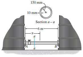
When the temperature is at 30°C, the A-36 steel pipe fits snugly between the two fuel tanks. When fuel flows through the pipe, it causes the temperature to vary along the pipe as T = (5/3 x2- 20x + 120)°C, where x is in meters. Determine the normal stress developed in the pipe. Assume each
Showing 800 - 900
of 983
1
2
3
4
5
6
7
8
9
10
Step by Step Answers