New Semester
Started
Get
50% OFF
Study Help!
--h --m --s
Claim Now
Question Answers
Textbooks
Find textbooks, questions and answers
Oops, something went wrong!
Change your search query and then try again
S
Books
FREE
Study Help
Expert Questions
Accounting
General Management
Mathematics
Finance
Organizational Behaviour
Law
Physics
Operating System
Management Leadership
Sociology
Programming
Marketing
Database
Computer Network
Economics
Textbooks Solutions
Accounting
Managerial Accounting
Management Leadership
Cost Accounting
Statistics
Business Law
Corporate Finance
Finance
Economics
Auditing
Tutors
Online Tutors
Find a Tutor
Hire a Tutor
Become a Tutor
AI Tutor
AI Study Planner
NEW
Sell Books
Search
Search
Sign In
Register
study help
engineering
mechanical engineering
Shigleys Mechanical Engineering Design 9th edition Richard G. Budynas, J. Keith Nisbett - Solutions
Repeat Prob. 3€“74 except for a contact force at E of (FE)CD = €“46.6i €“ 140j + 406k lbf and a shaft diameter of 1.0 in.Repeat Prob. 3€“74, In the figure, shaft AB transmits power to shaft CD through a set of bevel gears contacting at point E. The contact
Repeat the analysis of Prob. 3€“74 for shaft AB. Assume that bearing A carries the thrust load.Prob. 3€“74, In the figure, shaft AB transmits power to shaft CD through a set of bevel gears contacting at point E. The contact force at E on the gear of shaft CD is determined to be
A torque T = 100 N · m is applied to the shaft EFG, which is running at constant speed and contains gear F. Gear F transmits torque to shaft ABCD through gear C, which drives the chain sprocket at B, transmitting a force P as shown. Sprocket B, gear C, and gear F have pitch diameters of a =
Repeat Prob. 3€“77 with the chain parallel to the z axis with P in the positive z direction.Repeat Prob. 3€“77, A torque T = 100 N · m is applied to the shaft EFG, which is running at constant speed and contains gear F. Gear F transmits torque to shaft ABCD through gear
Repeat Prob. 3€“77 with T = 900 lbf · in, a = 6 in, b = 5 in, c = 10 in, d = 1.375 in, e = 4 in, f = 10 in, and g = 6 in.Repeat Prob. 3€“77, A torque T = 100 N · m is applied to the shaft EFG, which is running at constant speed and contains gear F. Gear F transmits
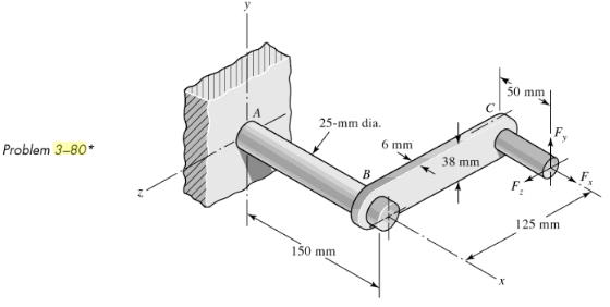
The cantilevered bar in the figure is made from a ductile material and is statically loaded with Fy = 200 lbf and Fx = Fz = 0. Analyze the stress situation in rod AB by obtaining the following information.(a) Determine the precise location of the critical stress element.(b) Sketch the critical
Repeat Prob. 3€“80 with Fx = 0, Fy = 175 lbf, and Fz = 100 lbf.Repeat Prob. 3€“80, The cantilevered bar in the figure is made from a ductile material and is statically loaded with Fy = 200 lbf and Fx = Fz = 0. Analyze the stress situation in rod AB by obtaining the following
Repeat Prob. 3€“80 with Fx = 75 lbf, Fy = ˆ’200 lbf, and Fz = 100 lbf.Repeat Prob. 3€“80, The cantilevered bar in the figure is made from a ductile material and is statically loaded with Fy = 200 lbf and Fx = Fz = 0. Analyze the stress situation in rod AB by obtaining
For the handle in Prob. 3–80, one potential failure mode is twisting of the flat plate BC. Determine the maximum value of the shear stress due to torsion in the main section of the plate, ignoring the complexities of the interfaces at B and C.In Prob. 3–80, The cantilevered bar in the figure is
The cantilevered bar in the figure is made from a ductile material and is statically loaded with Fy = 250 lbf and Fx = Fz = 0. Analyze the stress situation in the small diameter at the shoulder at A by obtaining the following information.(a) Determine the precise location of the critical stress
Repeat Prob. 3€“84 with Fx = 300 lbf, Fy = 250 lbf, and Fz = 0.Repeat Prob. 3€“84, The cantilevered bar in the figure is made from a ductile material and is statically loaded with Fy = 250 lbf and Fx = Fz = 0. Analyze the stress situation in the small diameter at the shoulder at
Repeat Prob. 3€“84 with Fx = 300 lbf, Fy = 250 lbf, and Fz = €“100 lbf.Repeat Prob. 3€“84, The cantilevered bar in the figure is made from a ductile material and is statically loaded with Fy = 250 lbf and Fx = Fz = 0. Analyze the stress situation in the small diameter
Repeat Prob. 3€“84 for a brittle material, requiring the inclusion of stress concentration in the fillet radius.Repeat Prob. 3€“84, The cantilevered bar in the figure is made from a ductile material and is statically loaded with Fy = 250 lbf and Fx = Fz = 0. Analyze the stress
Repeat Prob. 3€“84 with Fx = 300 lbf, Fy = 250 lbf, and Fz = 0, and for a brittle material, requiring the inclusion of stress concentration in the fillet radius.Repeat Prob. 3€“84, The cantilevered bar in the figure is made from a ductile material and is statically loaded with
Repeat Prob. 3€“84 with Fx = 300 lbf, Fy = 250 lbf, and Fz = €“100 lbf, and for a brittle material, requiring the inclusion of stress concentration in the fillet radius.Repeat Prob. 3€“84, The cantilevered bar in the figure is made from a ductile material and is
The figure shows a simple model of the loading of a square thread of a power screw transmitting an axial load F with an application of torque T. The torque is balanced by the frictional force Ff acting along the top surface of the thread. The forces on the thread are considered to be distributed
Develop the equations for the principal stresses in a thin-walled spherical pressure vessel of inside diameter di, thickness t, and with an internal pressure pi. You may wish to follow a process similar to that used for a thin-walled cylindrical pressure vessel on p. 114.
A pressure cylinder has an outer diameter do, wall thickness t, internal pressure pi, and maximum allowable shear stress Ï„max. In the table given, determine the appropriate value ofx.
A pressure cylinder has an outer diameter do, wall thickness t, internal pressure pi, and maximum allowable shear stress Ï„max. In the table given, determine the appropriate value ofx.
A pressure cylinder has an outer diameter do, wall thickness t, internal pressure pi, and maximum allowable shear stress Ï„max. In the table given, determine the appropriate value ofx.
A pressure cylinder has an outer diameter do, wall thickness t, external pressure po, and maximum allowable shear stress Ï„max. In the table given, determine the appropriate value ofx.
A pressure cylinder has an outer diameter do, wall thickness t, external pressure po, and maximum allowable shear stress Ï„max. In the table given, determine the appropriate value ofx.
A pressure cylinder has an outer diameter do, wall thickness t, external pressure po, and maximum allowable shear stress Ï„max. In the table given, determine the appropriate value ofx.
An AISI 1040 cold-drawn steel tube has an OD = 50 mm and wall thickness 6 mm. What maximum external pressure can this tube withstand if the largest principal normal stress is not to exceed 80 percent of the minimum yield strength of the material?
Repeat Prob. 3–100 with an OD of 2 in and wall thickness of 0.25 in.Repeat Prob. 3–100, An AISI 1040 cold-drawn steel tube has an OD = 50 mm and wall thickness 6 mm. What maximum external pressure can this tube withstand if the largest principal normal stress is not to exceed 80 percent of the
Repeat Prob. 3–100 with an internal pressure.Repeat Prob. 3–100, An AISI 1040 cold-drawn steel tube has an OD = 50 mm and wall thickness 6 mm. What maximum external pressure can this tube withstand if the largest principal normal stress is not to exceed 80 percent of the minimum yield strength
Repeat Prob. 3–101 with an internal pressure.Repeat Prob. 3–101, An AISI 1040 cold-drawn steel tube has an OD = 50 mm and wall thickness 6 mm. What maximum external pressure can this tube withstand if the largest principal normal stress is not to exceed 80 percent of the minimum yield strength
A thin-walled cylindrical steel water storage tank 30 ft in diameter and 60 ft long is oriented with its longitudinal axis vertical. The tank is topped with a hemispherical steel dome. The wall thickness of the tank and dome is 0.75 in. If the tank is unpressurized and contains water 55 ft above
Repeat Prob. 3–104 with the tank being pressurized to 50 psig.Repeat Prob. 3–104, A thin-walled cylindrical steel water storage tank 30 ft in diameter and 60 ft long is oriented with its longitudinal axis vertical. The tank is topped with a hemispherical steel dome. The wall thickness of the
Find the maximum shear stress in a 5 ½-in-diameter circular saw blade if it runs idle at 5000 rev/min. The saw is 14 gauge (0.0747 in) steel and is used on a 5/8-in-diameter arbor. The thickness is uniform.What is the maximum radial component of stress?
The maximum recommended speed for a 250-mm-diameter abrasive grinding wheel is 2000 rev/min. Assume that the material is isotropic; use a bore of 20 mm, ν = 0.24, and a mass density of 3320 kg/m3, and find the maximum tensile stress at this speed.
An abrasive cutoff wheel has a diameter of 5 in, is 1/16 in thick, and has a ¾-in bore. It weighs 5 oz and is designed to run at 12 000 rev/min. If the material is isotropic and ν = 0.20, find the maximum shear stress at the design speed.
A rotary lawnmower blade rotates at 3500 rev/min. The steel blade has a uniform cross section 1/8 in thick by 1 ¼ in wide, and has a ½-in-diameter hole in the center as shown in the figure. Estimate the nominal tensile stress at the central section due torotation.
The table lists the maximum and minimum hole and shaft dimensions for a variety of standard press and shrink fits. The materials are both hot-rolled steel. Find the maximum and minimum values of the radial interference and the corresponding interface pressure. Use a collar diameter of 100 mm for
The table lists the maximum and minimum hole and shaft dimensions for a variety of standard press and shrink fits. The materials are both hot-rolled steel. Find the maximum and minimum values of the radial interference and the corresponding interface pressure. Use a collar diameter of 100 mm for
The table lists the maximum and minimum hole and shaft dimensions for a variety of standard press and shrink fits. The materials are both hot-rolled steel. Find the maximum and minimum values of the radial interference and the corresponding interface pressure. Use a collar diameter of 100 mm for
The table lists the maximum and minimum hole and shaft dimensions for a variety of standard press and shrink fits. The materials are both hot-rolled steel. Find the maximum and minimum values of the radial interference and the corresponding interface pressure. Use a collar diameter of 100 mm for
The table lists the maximum and minimum hole and shaft dimensions for a variety of standard press and shrink fits. The materials are both hot-rolled steel. Find the maximum and minimum values of the radial interference and the corresponding interface pressure. Use a collar diameter of 100 mm for
The table lists the maximum and minimum hole and shaft dimensions for a variety of standard press and shrink fits. The materials are both hot-rolled steel. Find the maximum and minimum values of the radial interference and the corresponding interface pressure. Use a collar diameter of 100 mm for
The table gives data concerning the shrink fit of two cylinders of differing materials and dimensional specification in inches. Elastic constants for different materials may be found in Table A–5. Identify the radial interference δ, then find the interference pressure p, and the
The table gives data concerning the shrink fit of two cylinders of differing materials and dimensional specification in inches. Elastic constants for different materials may be found in Table A€“5. Identify the radial interference δ, then find the interference pressure p, and
The table gives data concerning the shrink fit of two cylinders of differing materials and dimensional specification in inches. Elastic constants for different materials may be found in Table A€“5. Identify the radial interference δ, then find the interference pressure p, and
The table gives data concerning the shrink fit of two cylinders of differing materials and dimensional specification in inches. Elastic constants for different materials may be found in Table A–5. Identify the radial interference δ, then find the interference pressure p, and the
A utility hook was formed from a round rod of diameter d = 20 mm into the geometry shown in the figure. What are the stresses at the inner and outer surfaces at section A€“A if F = 4 kN, L = 250 mm, and Di = 75mm?
Repeat Prob. 3€“120 with d = 0.75 in, F = 750 lbf, L = 10 in, and Di = 2.5 in.Repeat Prob. 3€“120, A utility hook was formed from a round rod of diameter d = 20 mm into the geometry shown in the figure. What are the stresses at the inner and outer surfaces at section
The steel eyebolt shown in the figure is loaded with a force F = 300 N. The bolt is formed from wire of diameter d = 6 mm to a radius R = 10 mm in the eye and at the shank. Estimate the stresses at the inner and outer surfaces at sectionA€“A.
For Prob. 3€“122 estimate the stresses at the inner and outer surfaces at section B€“B.Prob, 3-122, The steel eyebolt shown in the figure is loaded with a force F = 300 N. The bolt is formed from wire of diameter d = 6 mm to a radius R = 10 mm in the eye and at the shank.
Repeat Prob. 3–122 with d = ¼ in, R = 12 in, and F = 75 lbf.Repeat Prob. 3–122, The steel eyebolt shown in the figure is loaded with a force F = 300 N. The bolt is formed from wire of diameter d = 6 mm to a radius R = 10 mm in the eye and at the shank. Estimate the stresses at the
Repeat Prob. 3€“123 with d = ¼ in, R = 12 in, and F = 75 lbf.Repeat Prob. 3€“123, The steel eyebolt shown in the figure is loaded with a force F = 300 N. The bolt is formed from wire of diameter d = 6 mm to a radius R = 10 mm in the eye and at the shank. Estimate the
Shown in the figure is a 12-gauge (0.1094-in) by ¾ -in latching spring that supports a load of F = 3 lbf. The inside radius of the bend is 1/8 in.(a) Using straight-beam theory, determine the stresses at the top and bottom surfaces immediately to the right of the bend.(b) Using curved-beam
Repeat Prob. 3€“126 with a 10-gauge (0.1406-in) material thickness.Repeat Prob. 3€“126, Shown in the figure is a 12-gauge (0.1094-in) by ¾ -in latching spring that supports a load of F = 3 lbf. The inside radius of the bend is 1/8 in.(a) Using straight-beam theory,
Repeat Prob. 3€“126 with a bend radius of ¼ in.Repeat Prob. 3€“126, Shown in the figure is a 12-gauge (0.1094-in) by ¾ -in latching spring that supports a load of F = 3 lbf. The inside radius of the bend is 1/8 in.(a) Using straight-beam theory, determine the
The cast-iron bell-crank lever depicted in the figure is acted upon by forces F1 of 2.4 kN and F2 of 3.2 kN. The section A€“A at the central pivot has a curved inner surface with a radius of ri = 25 mm. Estimate the stresses at the inner and outer surfaces of the curved portion of
The crane hook depicted in Fig. 3€“35 has a 34-in-diameter hole in the center of the critical section. For a load of 6 kip, estimate the bending stresses at the inner and outer surfaces at the critical section.Figure 3€“35(a) Plan view of crane hook;(b) Cross section and
An offset tensile link is shaped to clear an obstruction with a geometry as shown in the figure. The cross section at the critical location is elliptical, with a major axis of 3 in and a minor axis of 1.5 in. For a load of 20 kip, estimate the stresses at the inner and outer surfaces of the
A cast-steel C frame as shown in the figure has a rectangular cross section of 1.25 in by 2 in, with a 0.5-in-radius semicircular notch on both sides that forms midflank fluting as shown. Estimate A, rc, rn, and e, and for a load of 2000 lbf, estimate the inner and outer surface stresses at the
Two carbon steel balls, each 30 mm in diameter, are pressed together by a force F. In terms of the force F, find the maximum values of the principal stress, and the maximum shear stress, in MPa.
A carbon steel ball with 25-mm diameter is pressed together with an aluminum ball with a 40-mm diameter by a force of 10 N. Determine the maximum shear stress, and the depth at which it will occur for the aluminum ball. Assume Fig. 3–37, which is based on a typical Poisson’s ratio of 0.3, is
Repeat Prob. 3–134 but determine the maximum shear stress and depth for the steel ball.Repeat Prob. 3–134, A carbon steel ball with 25-mm diameter is pressed together with an aluminum ball with a 40-mm diameter by a force of 10 N. Determine the maximum shear stress, and the depth at which it
A carbon steel ball with a 30-mm diameter is pressed against a flat carbon steel plate with a force of 20 N. Determine the maximum shear stress, and the depth in the plate at which it will occur.
An AISI 1018 steel ball with 1-in diameter is used as a roller between a flat plate made from 2024 T3 aluminum and a flat table surface made from ASTM No. 30 gray cast iron. Determine the maximum amount of weight that can be stacked on the aluminum plate without exceeding a maximum shear stress of
An aluminum alloy cylindrical roller with diameter 1.25 in and length 2 in rolls on the inside of a cast-iron ring having an inside radius of 6 in, which is 2 in thick. Find the maximum contact force F that can be used if the shear stress is not to exceed 4000 psi.
A pair of mating steel spur gears with a 0.75-in face width transmits a load of 40 lbf. For estimating the contact stresses, make the simplifying assumption that the teeth profiles can be treated as cylindrical with instantaneous radii at the contact point of interest of 0.47 in and 0.62 in,
A wheel of diameter d and width w carrying a load F rolls on a flat rail. Assume that Fig. 3€“39, which is based on a Poisson€™s ratio of 0.3, is applicable to estimate the depth at which the maximum shear stress occurs for these materials. At this critical depth, calculate the
A wheel of diameter d and width w carrying a load F rolls on a flat rail. Assume that Fig. 3€“39, which is based on a Poisson€™s ratio of 0.3, is applicable to estimate the depth at which the maximum shear stress occurs for these materials. At this critical depth, calculate the
A wheel of diameter d and width w carrying a load F rolls on a flat rail. Assume that Fig. 3€“39, which is based on a Poisson€™s ratio of 0.3, is applicable to estimate the depth at which the maximum shear stress occurs for these materials. At this critical depth, calculate the
A torsion-bar spring consists of a prismatic bar, usually of round cross section, that is twisted at one end and held fast at the other to form a stiff spring. An engineer needs a stiffer one than usual and so considers building in both ends and applying the torque somewhere in the central portion
An engineer is forced by geometric considerations to apply the torque on the spring of Prob. 4–3 at the location x = 0.4l. For a uniform-diameter spring, this would cause one leg of the span to be underutilized when both legs have the same diameter. For optimal design the diameter of each leg
A bar in tension has a circular cross section and includes a tapered portion of length l, as shown.(a) For the tapered portion, use Eq. (4€“3) in the form of δ = ˆ« l0[F/(AE)] dx to show thatδ = 4/Ï€ Fl/d1d2E(b) Determine the elongation of
Instead of a tensile force, consider the bar in Prob. 4€“5 to be loaded by a torque T.(a) Use Eq. (4€“5) in the form of θ = ˆ«l0[T/(GJ)] dx to show that the angle of twist of the tapered portion is(b) Using the same geometry as in Prob. 4€“5b
When a vertically suspended hoisting cable is long, the weight of the cable itself contributes to the elongation. If a 500-ft steel cable has an effective diameter of 0.5 in and lifts a load of 5000 lbf, determine the total elongation and the percent of the total elongation due to the cable’s own
Derive the equations given for beam 2 in Table A–9 using statics and the double-integration method.
Derive the equations given for beam 5 in Table A–9 using statics and the double-integration method.
The figure shows a cantilever consisting of steel angles size 100 × 100 × 12 mm mounted back to back.Using superposition, find the deflection at B and the maximum stress in thebeam.
A simply supported beam loaded by two forces is shown in the figure. Select a pair of structural steel channels mounted back to back to support the loads in such a way that the deflection at midspan will not exceed ½ in and the maximum stress will not exceed 15 kpsi.Usesuperposition.
Using superposition, find the deflection of the steel shaft at A in the figure. Find the deflection at midspan.By what percentage do these two valuesdiffer?
A rectangular steel bar supports the two overhanging loads shown in the figure.Using superposition, find the deflection at the ends and at thecenter.
An aluminum tube with outside diameter of 2 in and inside diameter of 1.5 in is cantilevered and loaded as shown.Using the formulas in Appendix Table A€“9 and superposition, find the deflection atB.
The cantilever shown in the figure consists of two structural-steel channels size 3 in, 5.0 lbf/ft.Using superposition, find the deflection at A. Include the weight of thechannels.
Using superposition for the bar shown, determine the minimum diameter of a steel shaft for which the maximum deflection is 2mm.
A simply supported beam has a concentrated moment MA applied at the left support and a concentrated force F applied at the free end of the overhang on the right.Using superposition, determine the deflection equations in regions AB andBC.
Calculating beam deflections using superposition is quite convenient provided you have a comprehensive table to refer to. Because of space limitations, this book provides a table that covers a great deal of applications, but not all possibilities. Problem 4€“19 is not directly solvable
Using the results of Prob 4€“18, use superposition to determine the deflection equations for the three regions of the beam shown.Prob 4€“18, Calculating beam deflections using superposition is quite convenient provided you have a comprehensive table to refer to. Because of space
Like Prob. 4€“18, this problem provides another beam to add to Table A€“9. For the simply supported beam shown with an overhanging uniform load, use statics and double integration to showthat
Consider the uniformly loaded simply supported steel beam with an overhang as shown. The second-area moment of the beam is I = 0.05 in4. Use superposition (with Table A–9 and the results of Prob. 4–20) to determine the reactions and the deflection equations of the beam.Plot the
Illustrated is a rectangular steel bar with simple supports at the ends and loaded by a force F at the middle; the bar is to act as a spring. The ratio of the width to the thickness is to be about b = 10h, and the desired spring scale is 1800 lbf/in.(a) Find a set of cross-section dimensions, using
For the steel countershaft specified in the table, find the deflection and slope of the shaft at point A. Use superposition with the deflection equations in Table A–9. Assume the bearings constitute simple supports.Problem 3-68, A countershaft carrying two V-belt pulleys is shown in the
For the steel countershaft specified in the table, find the deflection and slope of the shaft at point A. Use superposition with the deflection equations in Table A–9. Assume the bearings constitute simple supports.Problem 3-69, A countershaft carrying two V-belt pulleys is shown in the
For the steel countershaft specified in the table, find the deflection and slope of the shaft at point A. Use superposition with the deflection equations in Table A–9. Assume the bearings constitute simple supports.Problem 3-70, A countershaft carrying two V-belt pulleys is shown in the
For the steel countershaft specified in the table, find the deflection and slope of the shaft at point A. Use superposition with the deflection equations in Table A–9. Assume the bearings constitute simple supports.Problem 3-71
For the steel countershaft specified in the table, find the deflection and slope of the shaft at point A. Use superposition with the deflection equations in Table A–9. Assume the bearings constitute simple supports.Problem 3-73, A gear reduction unit uses the countershaft shown in the
For the steel countershaft specified in the table, find the deflection and slope of the shaft at point A. Use superposition with the deflection equations in Table A€“9. Assume the bearings constitute simple supports.Problem 3-73, A gear reduction unit uses the countershaft shown in the
For the steel countershaft specified in the table, find the slope of the shaft at each bearing. Use superposition with the deflection equations in Table A€“9. Assume the bearings constitute simple supports.Problem 3-68, A countershaft carrying two V-belt pulleys is shown in the figure.
For the steel countershaft specified in the table, find the slope of the shaft at each bearing. Use superposition with the deflection equations in Table A–9. Assume the bearings constitute simple supports.Problem 3-69, A countershaft carrying two V-belt pulleys is shown in the figure. Pulley
For the steel countershaft specified in the table, find the slope of the shaft at each bearing. Use superposition with the deflection equations in Table A€“9. Assume the bearings constitute simple supports.Problem 3-70, A countershaft carrying two V-belt pulleys is shown in the figure.
For the steel countershaft specified in the table, find the slope of the shaft at each bearing. Use superposition with the deflection equations in Table A–9. Assume the bearings constitute simple supports.Problem 3-71, A countershaft carrying two V-belt pulleys is shown in the figure. Pulley
For the steel countershaft specified in the table, find the slope of the shaft at each bearing. Use superposition with the deflection equations in Table A€“9. Assume the bearings constitute simple supports.Problem 3-73, A gear reduction unit uses the countershaft shown in the figure. Gear
For the steel countershaft specified in the table, find the slope of the shaft at each bearing. Use superposition with the deflection equations in Table A€“9. Assume the bearings constitute simple supports.Problem 3-73, A gear reduction unit uses the countershaft shown in the figure. Gear
For the steel countershaft specified in the table, assume the bearings have a maximum slope specification of 0.06° for good bearing life. Determine the minimum shaft diameter.Problem 3-68, A countershaft carrying two V-belt pulleys is shown in the figure. Pulley A receives power from a motor
For the steel countershaft specified in the table, assume the bearings have a maximum slope specification of 0.06° for good bearing life. Determine the minimum shaft diameter.Problem 3-69, A countershaft carrying two V-belt pulleys is shown in the figure. Pulley A receives power from a motor
Showing 13100 - 13200
of 18200
First
125
126
127
128
129
130
131
132
133
134
135
136
137
138
139
Last
Step by Step Answers
.png)
.png)
.png)
.png)
.png)
.png)
.png)
.png)
.png)
.png)
.png)
.png)
.png)
.png)
.png)
.png)
.png)
.png)
.png)
.png)
.png)
.png)
.png)
.png)
.png)
.png)
.png)
.png)
.png)
.png)
.png)
.png)
.png)
.png)
.png)
.png)
.png)
.png)
.png)
.png)
.png)
.png)
.png)
.png)
.png)
.png)
.png)
.png)
.png)
.png)
.png)
.png)
.png)
.png)
.png)
.png)
.png)
.png)
.png)
.png)
.png)
.png)
.png)
.png)
.png)
.png)
.png)
.png)
.png)
.png)
.png)
.png)
.png)
.png)
.png)
.png)
.png)
.png)

