New Semester
Started
Get
50% OFF
Study Help!
--h --m --s
Claim Now
Question Answers
Textbooks
Find textbooks, questions and answers
Oops, something went wrong!
Change your search query and then try again
S
Books
FREE
Study Help
Expert Questions
Accounting
General Management
Mathematics
Finance
Organizational Behaviour
Law
Physics
Operating System
Management Leadership
Sociology
Programming
Marketing
Database
Computer Network
Economics
Textbooks Solutions
Accounting
Managerial Accounting
Management Leadership
Cost Accounting
Statistics
Business Law
Corporate Finance
Finance
Economics
Auditing
Tutors
Online Tutors
Find a Tutor
Hire a Tutor
Become a Tutor
AI Tutor
AI Study Planner
NEW
Sell Books
Search
Search
Sign In
Register
study help
engineering
mechanical engineering
Shigleys Mechanical Engineering Design 9th edition Richard G. Budynas, J. Keith Nisbett - Solutions
A circular cross section O ring has the dimensions shown in the figure. In particular, an AS 568A standard No. 240 O ring has an inside diameter Di and a cross-section diameter d of Di = 3.734 ± 0.028 in d = 0.139 ± 0.004 inEstimate the mean outside diameter Do and its bilateral tolerance.
For the table given, repeat Prob. 1–17 for the following O rings, given the AS 568A standard number.Repeat Prob. 1–17, A circular cross section O ring has the dimensions shown in the figure. In particular, an AS 568A standard No. 240 O ring has an inside diameter Di and a
Solve Problems 1–19 using SI units.AS 568A No.220
Solve Problems 1–20 using ips units. AS 568A No. 160
Solve Problems 1–21 using ips units. AS 568A No. 320
Convert the following to appropriate ips units:(a) A stress, σ = 150 MPa.(b) A force, F = 2 kN.(c) A moment, M = 150 N ∙ m.(d) An area, A = 1 500 mm2.(e) A second moment of area, I = 750 cm4.(f) A modulus of elasticity, E = 145 GPa.(g) A speed, v = 75 km/h.(h) A volume, V = 1 liter.
Convert the following to appropriate SI units:(a) A length, l = 5 ft.(b) A stress, σ = 90 kpsi.(c) A pressure, p = 25 psi.(d) A section modulus, Z = 12 in3.(e) A unit weight, w = 0.208 lbf/in.(f) A deflection, δ = 0.001 89 in.(g) A velocity, v = 1 200 ft/min.(h) A unit strain, ϵ = 0.002 15
Generally, final design results are rounded to or fixed to three digits because the given data cannot justify a greater display. In addition, prefixes should be selected so as to limit number strings to no more than four digits to the left of the decimal point. Using these rules, as well as those
Repeat Prob. 1–24 for the following:(a) σ = F/wt, where F = 1 kN, w = 25 mm, and t = 5 mm.(b) I = bh3/12, where b = 10 mm and h = 25 mm.(c) I = πd4/64, where d = 25.4 mm.(d) τ = 16 T/πd3, where T = 25 N ∙ m, and d = 12.7 mm.
Repeat Prob. 1–24 for:(a) τ = F/A, where A = πd2/4, F = 2 700 lbf, and d = 0.750 in.(b) σ = 32 Fa/πd3, where F = 180 lbf, a = 31.5 in, and d = 1.25 in.(c) Z = π(d4o / di4)/(32 do) for do = 1.50 in and di = 1.00 in.(d) k = (d4 G)/(8 D3 N), where d = 0.062 5 in, G = 11.3 Mpsi, D = 0.760 in,
Determine the tensile and yield strengths for the following materials:(a) UNS G10200 hot-rolled steel.(b) SAE 1050 cold-drawn steel.(c) AISI 1141 steel quenched and tempered at 540°C.(d) 2024-T4 aluminum alloy.(e) Ti-6Al-4V annealed titanium alloy.
Assume you were specifying an AISI 1060 steel for an application. Using Table A–21,(a) How would you specify it if you desired to maximize the yield strength?(b) How would you specify it if you desired to maximize the ductility?
Determine the yield strength-to-weight density ratios (specific strength) in units of kN ∙ m/kg for AISI 1018 CD steel, 2011-T6 aluminum, Ti-6Al-4V titanium alloy, and ASTM No. 40 gray cast iron.
Determine the stiffness-to-weight density ratios (specific modulus) in units of inches for AISI 1018 CD steel, 2011-T6 aluminum, Ti-6Al-4V titanium alloy, and ASTM No. 40 gray cast iron.
A part made from annealed AISI 1018 steel undergoes a 20 percent cold-work operation.(a) Obtain the yield strength and ultimate strength before and after the cold-work operation. Determine the percent increase in each strength.(b) Determine the ratios of ultimate strength to yield strength before
Repeat Prob. 2–9 for a part made from hot-rolled AISI 1212 steel.Repeat Prob. 2–9, A part made from annealed AISI 1018 steel undergoes a 20 percent cold-work operation.(a) Obtain the yield strength and ultimate strength before and after the cold-work operation. Determine the percent increase in
Repeat Prob. 2–9 for a part made from 2024-T4 aluminum alloy.Repeat Prob. 2–9, A part made from annealed AISI 1018 steel undergoes a 20 percent cold-work operation.(a) Obtain the yield strength and ultimate strength before and after the cold-work operation. Determine the percent increase in
A gray cast iron part has a Brinell hardness number of HB = 200. Estimate the ultimate strength of the part in kpsi. Make a reasonable assessment of the likely grade of cast iron by comparing both hardness and strength to material options in Table A–24.
Brinell hardness tests were made on a random sample of 10 steel parts during processing. The results were HB values of 230, 232(2), 234, 235(3), 236(2), and 239. Estimate the mean and standard deviation of the ultimate strength in kpsi.
Repeat Prob. 2–15 assuming the material to be cast iron.Repeat Prob. 2–15, Brinell hardness tests were made on a random sample of 10 steel parts during processing. The results were HB values of 230, 232(2), 234, 235(3), 236(2), and 239. Estimate the mean and standard deviation of the ultimate
For the material in Prob. 2–6: (a) Determine the modulus of resilience, (b) Estimate the modulus of toughness, assuming that the last data point corresponds to fracture.
An application requires the support of an axial load of 100 kips with a round rod without exceeding the yield strength of the material. Assume the current cost per pound for round stock is given in the table below for several materials that are being considered. Material properties are available in
A 1-in-diameter rod, 3 ft long, of unknown material is found in a machine shop. A variety of inexpensive nondestructive tests are readily available to help determine the material, as described below:(a) Visual inspection.(b) Scratch test: Scratch the surface with a file; observe color of underlying
A 1-in-diameter rod, 3 ft long, of unknown material is found in a machine shop. A variety of inexpensive nondestructive tests are readily available to help determine the material, as described below:(a) Visual inspection.(b) Scratch test: Scratch the surface with a file; observe color of underlying
A 1-in-diameter rod, 3 ft long, of unknown material is found in a machine shop. A variety of inexpensive nondestructive tests are readily available to help determine the material, as described below:(a) Visual inspection.(b) Scratch test: Scratch the surface with a file; observe color of underlying
Consider a rod transmitting a tensile force. The following materials are being considered: tungsten carbide, high-carbon heat-treated steel, polycarbonate polymer, aluminum alloy. Using the Ashby charts, recommend one or two of the materials for a design situation in which failure is by exceeding
Repeat Prob. 2–26, except that the design situation is failure by excessive deflection, and it is desired to minimize the weight.Repeat Prob. 2–26, Consider a rod transmitting a tensile force. The following materials are being considered: tungsten carbide, high-carbon heat-treated steel,
Consider a cantilever beam that is loaded with a transverse force at its tip. The following materials are being considered: tungsten carbide, high-carbon heat-treated steel, polycarbonate polymer, aluminum alloy. Using the Ashby charts, recommend one or two of the materials for a design situation
Repeat Prob. 2–28, except that the design situation is failure by excessive deflection and it is desired to minimize the weight.Repeat Prob. 2–28, Consider a cantilever beam that is loaded with a transverse force at its tip. The following materials are being considered: tungsten carbide,
For an axially loaded rod, prove that β = 1 for the Eβ/Ï guidelines in Fig.2–16.
For an axially loaded rod, prove that β = 1 for the Sβ/Ï guidelines in Fig.2–19.
For a cantilever beam loaded in bending, prove that β = 1/2 for the Eβ/Ï guidelines in Fig.2–16.
For a cantilever beam loaded in bending, prove that b = 2/3 for the Sβ/Ï guidelines in Fig.2€“19.
Consider a tie rod transmitting a tensile force F. The corresponding tensile stress is given by σ = F/A, where A is the area of the cross section. The deflection of the rod is given by Eq. (4–3), which is δ = (Fl)/(AE), where l is the length of the rod. Using the Ashby charts of Figs. 2–16
Sketch a free-body diagram of each element in the figure. Compute the magnitude and direction of each force using an algebraic or vector method, asspecified.
Sketch a free-body diagram of each element in the figure. Compute the magnitude and direction of each force using an algebraic or vector method, asspecified.
Sketch a free-body diagram of each element in the figure. Compute the magnitude and direction of each force using an algebraic or vector method, asspecified.
Sketch a free-body diagram of each element in the figure. Compute the magnitude and direction of each force using an algebraic or vector method, asspecified.
For the beam shown, find the reactions at the supports and plot the shear-force and bending-moment diagrams. Label the diagrams properly and provide values at all keypoints.
For the beam shown, find the reactions at the supports and plot the shear-force and bending-moment diagrams. Label the diagrams properly and provide values at all keypoints.
For the beam shown, find the reactions at the supports and plot the shear-force and bending-moment diagrams. Label the diagrams properly and provide values at all keypoints.
For the beam shown, find the reactions at the supports and plot the shear-force and bending-moment diagrams. Label the diagrams properly and provide values at all keypoints.
Repeat Prob. 3€“5 using singularity functions exclusively (including reactions).Repeat Prob. 3€“5, For the beam shown, find the reactions at the supports and plot the shear-force and bending-moment diagrams. Label the diagrams properly and provide values at all keypoints.
Repeat Prob. 3€“6 using singularity functions exclusively (including reactions).Repeat Prob. 3€“6, For the beam shown, find the reactions at the supports and plot the shear-force and bending-moment diagrams. Label the diagrams properly and provide values at all keypoints.
Repeat Prob. 3€“7 using singularity functions exclusively (including reactions).Repeat Prob. 3€“7, For the beam shown, find the reactions at the supports and plot the shear-force and bending-moment diagrams. Label the diagrams properly and provide values at all keypoints.
Repeat Prob. 3€“8 using singularity functions exclusively (including reactions).Repeat Prob. 3€“8, For the beam shown, find the reactions at the supports and plot the shear-force and bending-moment diagrams. Label the diagrams properly and provide values at all keypoints.
A beam carrying a uniform load is simply supported with the supports set back a distance a from the ends as shown in the figure. The bending moment at x can be found from summing moments to zero at section x:ΣM = M + ½ w(a + x)2 €“ ½ wlx = 0OrM = w/2 [lx
For each of the plane stress states listed below, draw a Mohr’s circle diagram properly labeled, find the principal normal and shear stresses, and determine the angle from the x axis to σ1. Draw stress elements as in Fig. 3–11c and d and label all details.(a) σx = 20 kpsi, σy = −10 kpsi,
Repeat Prob. 3– 15 for:(a) σx = −8MPa, σy = 7MPa, τxy = 6MPa cw(b) σx = 9MPa, σy = −6MPa, τxy = 3MPa cw(c) σx = −4MPa, σy = 12MPa, τxy = 7MPa ccw(d) σx = 6MPa, σy = −5MPa, τxy = 8MPa ccw
Repeat Prob. 3– 15 for:(a) σx = 12 kpsi, σy = 6 kpsi, τxy = 4 kpsi cw(b) σx = 30 kpsi, σy = −10 kpsi, τxy = 10 kpsi ccw(c) σx = −10 kpsi, σy = 18 kpsi, τxy = 9 kpsi cw(d) σx = 9 kpsi, σy = 19 kpsi, τxy = 8 kpsi cw
Repeat Prob. 3–18 for:(a) σx = 10 kpsi, σy = −4 kpsi(b) σx = 10 kpsi, τxy = 4 kpsi ccw(c) σx = −2 kpsi, σy = −8 kpsi, τxy = 4 kpsi cw(d) σx = 10 kpsi, σy = −30 kpsi, τxy = 10 kpsi ccw
The state of stress at a point is σx = −6, σy = 18, σz = −12, τxy = 9, τyz = 6, and τzx = −15 kpsi. Determine the principal stresses, draw a complete Mohr’s three-circle diagram, labeling all points of interest, and report the maximum shear stress for this case.
Repeat Prob. 3–20 with σx = 20, σy = 0, σz = 20, τxy = 40, τyz = −20√2, and τzx = 0 kpsi. Repeat Prob. 3–20, the state of stress at a point is σx = −6, σy = 18, σz = −12, τxy = 9, τyz = 6, and τzx = −15 kpsi. Determine the principal stresses, draw a complete Mohr’s
Repeat Prob. 3–20 with σx = 10, σy = 40, σz = 40, τxy = 20, τyz = −40, and τzx = −20 MPa.Repeat Prob. 3–20, the state of stress at a point is σx = −6, σy = 18, σz = −12, τxy = 9, τyz = 6, and τzx = −15 kpsi. Determine the principal stresses, draw a complete Mohr’s
A ¾ -in-diameter steel tension rod is 5 ft long and carries a load of 15 kip. Find the tensile stress, the total deformation, the unit strains, and the change in the rod diameter.
Repeat Prob. 3–23 except change the rod to aluminum and the load to 3000 lbf.Repeat Prob. 3–23, A ¾ -in-diameter steel tension rod is 5 ft long and carries a load of 15 kip. Find the tensile stress, the total deformation, the unit strains, and the change in the rod diameter.
A 30-mm-diameter copper rod is 1 m long with a yield strength of 70 MPa. Determine the axial force necessary to cause the diameter of the rod to reduce by 0.01 percent, assuming elastic deformation. Check that the elastic deformation assumption is valid by comparing the axial stress to the yield
A diagonal aluminum alloy tension rod of diameter d and initial length l is used in a rectangular frame to prevent collapse. The rod can safely support a tensile stress of σallow. If d = 0.5 in, l = 8 ft, and σallow = 20 kpsi, determine how much the rod must be stretched to develop this allowable
Repeat Prob. 3–26 with d = 16 mm, l = 3 m, and σallow = 140 MPa.Repeat Prob. 3–26, A diagonal aluminum alloy tension rod of diameter d and initial length l is used in a rectangular frame to prevent collapse. The rod can safely support a tensile stress of σallow. If d = 0.5 in, l = 8 ft, and
Repeat Prob. 3–26 with d = 58 in, l = 10 ft, and σallow = 15 kpsi.Repeat Prob. 3–26, A diagonal aluminum alloy tension rod of diameter d and initial length l is used in a rectangular frame to prevent collapse. The rod can safely support a tensile stress of σallow. If d = 0.5 in, l = 8 ft, and
Electrical strain gauges were applied to a notched specimen to determine the stresses in the notch. The results were ϵx = 0.0019 and ϵy = −0.00072. Find σx and σy if the material is carbon steel.
Repeat Prob. 3–29 for a material of aluminum.Repeat Prob. 3–29, Electrical strain gauges were applied to a notched specimen to determine the stresses in the notch. The results were ϵx = 0.0019 and ϵy = −0.00072. Find σx and σy if the material is carbon steel.
For each section illustrated, find the second moment of area, the location of the neutral axis, and the distances from the neutral axis to the top and bottom surfaces. Consider that the section is transmitting a positive bending moment about the z axis, Mz, where Mz = 10 kip · in if the
For the beam illustrated in the figure, find the locations and magnitudes of the maximum tensile bending stress due to M and the maximum shear stress due toV.
For the beam illustrated in the figure, find the locations and magnitudes of the maximum tensile bending stress due to M and the maximum shear stress due toV.
For the beam illustrated in the figure, find the locations and magnitudes of the maximum tensile bending stress due to M and the maximum shear stress due toV.
For the beam illustrated in the figure, find the locations and magnitudes of the maximum tensile bending stress due to M and the maximum shear stress due toV.
The figure illustrates a number of beam sections. Use an allowable bending stress of 12 kpsi for steel and find the maximum safe uniformly distributed load that each beam can carry if the given lengths are between simple supports.(a) Standard 2-in × 1/4-in tube, 48 in long(b) Hollow
A pin in a knuckle joint carrying a tensile load F deflects somewhat on account of this loading, making the distribution of reaction and load as shown in part (b) of the figure. A common simplification is to assume uniform load distributions, as shown in part (c). To further simplify, designers may
Repeat Prob. 3€“40 for a = 6 mm, b = 18 mm, d = 12 mm, and F = 4 kN.Repeat Prob. 3€“40, A pin in a knuckle joint carrying a tensile load F deflects somewhat on account of this loading, making the distribution of reaction and load as shown in part (b) of the figure. A common
For the knuckle joint described in Prob. 3–40, assume the maximum allowable tensile stress in the pin is 30 kpsi and the maximum allowable shearing stress in the pin is 15 kpsi. Use the model shown in part c of the figure to determine a minimum pin diameter for each of the following potential
For the beam shown, determine(a) The maximum tensile and compressive bending stresses,(b) The maximum shear stress due to V,(c) The maximum shear stress in thebeam.
A cantilever beam with a 1-in-diameter round cross section is loaded at the tip with a transverse force of 1000 lbf, as shown in the figure. The cross section at the wall is also shown, with labeled points A at the top, B at the center, and C at the midpoint between A and B. Study the significance
In Prob. 3€“46, h †’ 0 as x †’0 which cannot occur. If the maximum shear stress Ï„max due to direct shear is to be constant in this region, show that the depth h at location x is givenby
The beam shown is loaded in the xy and xz planes.(a) Find the yz components of the reactions at the supports.(b) Plot the shear-force and bending-moment diagrams for the xy and xz planes. Label the diagrams properly and provide the values at key points.(c) Determine the net shear-force and
The beam shown is loaded in the xy and xz planes.(a) Find the yz components of the reactions at the supports.(b) Plot the shear-force and bending-moment diagrams for the xy and xz planes. Label the diagrams properly and provide the values at key points.(c) Determine the net shear-force and
Consider a 1-in-square steel thin-walled tube loaded in torsion. The tube has a wall thickness t = 1/16 in, is 36 in long, and has a maximum allowable shear stress of 12 kpsi. Determine the maximum torque that can be applied and the corresponding angle of twist of the tube.(a) Assume that the
The thin-walled open cross-section shown is transmitting torque T. The angle of twist per unit length of each leg can be determined separately using Eq. (3–47) and is given byθ1 = 3Ti/GLic3iWhere for this case, i = 1, 2, 3, and Ti represents the torque in leg i. Assuming that the angle of
Using the results from Prob. 3€“52, consider a steel section with Ï„allow = 12 kpsi.(a) Determine the torque transmitted by each leg and the torque transmitted by the entire section.(b) Determine the angle of twist per unitlength.
Using the results from Prob. 3–52, consider a steel section with τallow = 12 kpsi.(a) Determine the torque transmitted by each leg and the torque transmitted by the entire section.(b) Determine the angle of twist per unitlength.
Using the results from Prob. 3€“52, consider a steel section with Ï„allow = 12 kpsi.(a) Determine the torque transmitted by each leg and the torque transmitted by the entire section.(b) Determine the angle of twist per unitlength.
Two 300-mm-long rectangular steel strips are placed together as shown. Using a maximum allowable shear stress of 80 MPa, determine the maximum torque and angular twist, and the torsional spring rate. Compare these with a single strip of cross section 30 mm by 4 mm. Solve the problem two ways:(a)
Using a maximum allowable shear stress of 70 MPa, find the shaft diameter needed to transmit 40 kW when(a) The shaft speed is 2500 rev/min.(b) The shaft speed is 250 rev/min.
Repeat Prob. 3–57 with an allowable shear stress of 20 kpsi and a power of 50 hp.Repeat Prob. 3–57, Using a maximum allowable shear stress of 70 MPa, find the shaft diameter needed to transmit 40 kW when(a) The shaft speed is 2500 rev/min.(b) The shaft speed is 250 rev/min.
Using an allowable shear stress of 50 MPa, determine the power that can be transmitted at 2000 rpm through a shaft with a 30-mm diameter.
A 20-mm-diameter steel bar is to be used as a torsion spring. If the torsional stress in the bar is not to exceed 110 MPa when one end is twisted through an angle of 15°, what must be the length of the bar?
A 2-ft-long steel bar with a ¾ -in diameter is to be used as a torsion spring. If the torsional stress in the bar is not to exceed 30 kpsi, what is the maximum angle of twist of the bar?
A 40-mm-diameter solid steel shaft, used as a torque transmitter, is replaced with a hollow shaft having a 40-mm OD and a 36-mm ID. If both materials have the same strength, what is the percentage reduction in torque transmission? What is the percentage reduction in shaft weight?
Generalize Prob. 3–62 for a solid shaft of diameter d replaced with a hollow shaft of the same material with an outside diameter d, and an inside diameter that is a fraction of the outside diameter, x × d, where x is any fraction between zero and one. Obtain expressions for percentage reduction
A hollow steel shaft is to transmit 4200 N ・ m of torque and is to be sized so that the torsional stress does not exceed 120 MPa.(a) If the inside diameter is 70 percent of the outside diameter, what size shaft should be used? Use preferred sizes.(b) What is the stress on the inside of the shaft
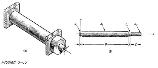
The figure shows an endless-belt conveyor drive roll. The roll has a diameter 120 mm and is driven at 10 rev/min by a geared-motor source rated at 1.5 kW. Determine a suitable shaft diameter dC for an allowable torsional stress of 80 MPa.(a) What would be the stress in the shaft you have sized if
The conveyer drive roll in the figure for Prob. 3–65 is 5 in diameter and is driven at 8 rev/min by a geared-motor source rated at 1 hp. Find a suitable shaft diameter dC based on an allowable torsional stress of 15 kpsi.
Consider two shafts in torsion, each of the same material, length, and cross-sectional area. One shaft has a solid square cross section and the other shaft has a solid circular section.(a) Which shaft has the greater maximum shear stress and by what percentage?(b) Which shaft has the greater
A countershaft carrying two V-belt pulleys is shown in the figure. Pulley A receives power from a motor through a belt with the belt tensions shown. The power is transmitted through the shaft and delivered to the belt on pulley B. Assume the belt tension on the loose side at B is 15 percent of the
A countershaft carrying two V-belt pulleys is shown in the figure. Pulley A receives power from a motor through a belt with the belt tensions shown. The power is transmitted through the shaft and delivered to the belt on pulley B. Assume the belt tension on the loose side at B is 15 percent of the
A countershaft carrying two V-belt pulleys is shown in the figure. Pulley A receives power from a motor through a belt with the belt tensions shown. The power is transmitted through the shaft and delivered to the belt on pulley B. Assume the belt tension on the loose side at B is 15 percent of the
A countershaft carrying two V-belt pulleys is shown in the figure. Pulley A receives power from a motor through a belt with the belt tensions shown. The power is transmitted through the shaft and delivered to the belt on pulley B. Assume the belt tension on the loose side at B is 15 percent of the
A gear reduction unit uses the countershaft shown in the figure. Gear A receives power from another gear with the transmitted force FA applied at the 20_ pressure angle as shown. The power is transmitted through the shaft and delivered through gear B through a transmitted force FB at the pressure
A gear reduction unit uses the countershaft shown in the figure. Gear A receives power from another gear with the transmitted force FA applied at the 20_ pressure angle as shown. The power is transmitted through the shaft and delivered through gear B through a transmitted force FB at the pressure
In the figure, shaft AB transmits power to shaft CD through a set of bevel gears contacting at point E. The contact force at E on the gear of shaft CD is determined to be (FE)CD = €“92.8i €“ 362.8j + 808.0k lbf. For shaft CD:(a) Draw a free-body diagram and determine the
Showing 13000 - 13100
of 18200
First
124
125
126
127
128
129
130
131
132
133
134
135
136
137
138
Last
Step by Step Answers
.png)
.png)
.png)
.png)
.png)
.png)
.png)
.png)
.png)
.png)
.png)
.png)
.png)
.png)
.png)
.png)
.png)
.png)
.png)
.png)
.png)
.png)
.png)
.png)
.png)
.png)
.png)
.png)
.png)
.png)
.png)
.png)
.png)
.png)
.png)
.png)
.png)
.png)
.png)
.png)
.png)
.png)
.png)
.png)
.png)
.png)

