New Semester
Started
Get
50% OFF
Study Help!
--h --m --s
Claim Now
Question Answers
Textbooks
Find textbooks, questions and answers
Oops, something went wrong!
Change your search query and then try again
S
Books
FREE
Study Help
Expert Questions
Accounting
General Management
Mathematics
Finance
Organizational Behaviour
Law
Physics
Operating System
Management Leadership
Sociology
Programming
Marketing
Database
Computer Network
Economics
Textbooks Solutions
Accounting
Managerial Accounting
Management Leadership
Cost Accounting
Statistics
Business Law
Corporate Finance
Finance
Economics
Auditing
Tutors
Online Tutors
Find a Tutor
Hire a Tutor
Become a Tutor
AI Tutor
AI Study Planner
NEW
Sell Books
Search
Search
Sign In
Register
study help
physics
thermodynamics
A First Course in the Finite Element Method 6th edition Daryl L. Logan - Solutions
For the five-spring assemblage shown in Figure P2-17, determine the displacements at nodes 2 and 3 and the reactions at nodes 1 and 4. Assume the rigid vertical bars at nodes 2 and 3 connecting the springs remain horizontal at all times but are free to slide or displace left or right. There is an
Use the principle of minimum potential energy developed in Section 2.6 to solve the spring problems shown in Figure P2-18. That is, plot the total potential energy for variations in the displacement of the free end of the spring to determine the minimum potential energy. Observe that the
Reverse the direction of the load in Example 2.4 and recalculate the total potential energy. Then use this value to obtain the equilibrium value of displacement.Example 2.4For the linear-elastic spring subjected to a force of 1000 lb shown in Figure 2-20, evaluate the potential energy for various
For the spring assemblage shown in Figure P2-2, determine the displacement at node 2 and the forces in each spring element. Also determine the force F3. Given: Node 3 displaces an amount δ = 1 in. in the positive x direction because of the force F3 and k1 = k2 = 1000 lb/in.Figure P2-2
The nonlinear spring in Figure P2-20 has the force/deformation relationship f = kδ2. Express the total potential energy of the spring, and use this potential energy to obtain the equilibrium value of displacement.Figure P2-20
Solve Problems 2.10 and 2.15 by the potential energy approach (see Example 2.5).Figure P2-10Figure P2-15
Resistor type elements are often used in electrical circuits. Consider the typical resistor element shown in Figure P2-23 with nodes 1 and 2. One form of Ohm's law says that the potential voltage difference across two points is equal to the current I through the conductor times the resistance R
a. For the spring assemblage shown in Figure P2-3, obtain the global stiffness matrix by direct superposition.b. If nodes 1 and 5 are fixed and a force P is applied at node 3, determine the nodal displacements.c. Determine the reactions at the fixed nodes 1 and 5.Figure P2-3
Solve Problem 2.3 with P = 0 (no force applied at node 3) and with node 5 given a fixed, known displacement of δ as shown in Figure P2-4.Figure P2-4
For the spring assemblage shown in Figure P2-5, obtain the global stiffness matrix by the direct stiffness method. Let k(1) = 1 kip in., k(2) = 2 kip in., k(3) = 3 kip in., k(4) = 4 kip/in., and k(5) = 5 kip/in.Figure P2-5
For the spring assemblage in Figure P2-5, apply a concentrated force of 3 kips at node 2 in the positive x direction and determine the displacements at nodes 2 and 4.Figure P2-5
Instead of assuming a tension element as in Figure P2-3, now assume a compression element. That is, apply compressive forces to the spring element and derive the stiffness matrix.Figure P2-3
For the spring assemblages shown in Figures P2-8 through P2-16, determine the nodal displacements, the forces in each element, and the reactions. Use the direct stiffness method for all problems.Figure P2-8Figure P2-9Figure P2-10Figure P2-11Figure P2-12Figure P2-13Figure P2-14Figure P2-15Figure
a. Compute the total stiffness matrix [K] of the assemblage shown in Figure P3-1 by superimposing the stiffness matrices of the individual bars. Note that [K] should be in terms of A1, A2, A3, E1, E2, E3, L1, L2, and L3. Here A, E, and L are generic symbols used for cross-sectional area, modulus of
Solve for the axial displacement and stress in the tapered bar shown in Figure P3-12 using one and then two constant-area elements. Evaluate the area at the center of each element length. Use that area for each element. Let A0 = 2 in2, L = 20 in., E = 10 × 106 psi, and P = 1000 lb. Compare your
Determine the stiffness matrix for the bar element with end nodes and mid length node shown in Figure P3-13. Let axial displacement u = α1 + α2x + α3x2. (This is a higher-order element in that strain now varies linearly through the element.)Figure P3-13
Consider the following displacement function for the two-noded bar element:u = α + bx2Is this a valid displacement function? Discuss why or why not.
For each of the bar elements shown in Figure P3-15, evaluate the global x - y stiffness matrix.Figure P3-15(a)(b)
For the bar elements shown in Figure P3-16, the global displacement have been determined to be u1 = 0.5 in., v1 = 0.0, u2 = 0.25 in., and v2 = 0.75 in. Determine the local x' displacements at each end of the bars. Let E = 12 × 106 psi, A = 0.5 in2, and L = 60 in. for each element?Figure
For the bar elements shown in Figure P3-17, the global displacements have been determined to be u1 = 0.0, v1 = 2.5 mm, u2 = 5.0 mm, and v2 = 3.0 mm. Determine the local x' displacements at the ends of each bar. Let E = 210 GPa, A = 10 × 10-4 m2, and L = 3 m for each element.Figure P3-17(a)(b)
Using the method of Section 3.5, determine the axial stress in each of the bar elements shown in Figure P3-18.(a)(b)
a. Assemble the stiffness matrix for the assemblage shown in Figure P3-19 by super-imposing the stiffness matrices of the springs. Here k is the stiffness of each spring.b. Find the x and y components of deflection of node 1.Figure P3-19
For the bar assemblages shown in Figures P3-2 through P3-11, determine the nodal displacements, the forces in each element, and the reactions. Use the direct stiffness method for these problems.Figure P3-2,Figure P3-3,Figure P3-4,Figure P3-5,Figure P3-6,Figure P3-7,Figure P3-8,Figure P3-9,Figure
For the plane truss structure shown in Figure P3-20, determine the displacement of node 2 using the stiffness method. Also determine the stress in element 1. Let A = 10 in2, E = 1 × 10⁶ psi, and L = 100 in.Figure P3-20
Find the horizontal and vertical displacements of node 1 for the truss shown in Figure P3-21. Assume AE = 30 × 106 lb is the same for each element?Figure P3-21
For the truss shown in Figure P3-22 solve for the horizontal and vertical components of displacement at node 1 and determine the stress in each element. Also verify force equilibrium at node 1. All elements have A = 1 in.2 and E = 10 × 106 psi. Let L = 100 in.Figure P3-22
For the truss shown in Figure P3-23, solve for the horizontal and vertical components of displacement at node 1. Also determine the stress in element 1. Let A = 1in2, E = 10.0 × 10⁶ psi, and L = 100 in.Figure P3-23
Determine the nodal displacements and the element forces for the truss shown in Figure P3-24. Assume all elements have the same AE.Figure P3-24
Now remove the element connecting nodes 2 and 4 in Figure P3-24. Then determine the nodal displacements and element forces.Figure P3-24
Now remove both cross elements in Figure P3-24. Can you determine the nodal displacements? If not, why?Figure P3-24,
Determine the displacement components at node 3 and the element forces for the plane truss shown in Figure P3-27. Let A = 3 in2 and E = 30 × 106 psi for all elements. Verify force equilibrium at node 3.Figure P3-27
Show that for the transformation matrix [T] of Eq. (3.4.15), [T]T 5[T]-1 and hence Eq. (3.4.21) is indeed correct, thus also illustrating that [k] = [T]T [k'][T] is the expression for the global stiffness matrix for an element?
For the plane trusses shown in Figures P3-29 and P3-30, determine the horizontal and vertical displacements of node 1 and the stresses in each element. All elements have E = 210 GPa and A = 4.0 ×10⁻⁴ m2.Figure P3-29,Figure P3-30,
Remove element 1 from Figure P3-30 and solve the problem. Compare the displacements and stresses to the results for Problem 3.30.Figure P3-30
For the plane truss shown in Figure P3-32, determine the nodal displacements, the element forces and stresses, and the support reactions. All elements have E = 70 GPa and A = 3.0 × 10⁻⁴ m2. Verify force equilibrium at nodes 2 and 4. Use symmetry in your model.Figure P3-32
For the plane trusses supported by the spring at node 1 in Figure P3-33 (a) and (b), determine the nodal displacements and the stresses in each element. Let E = 210 GPa and A × 5.0 × 10⁻⁴ m2 for both truss elements.Figure P3-33(a)Figure P3-33(b)
For the plane truss shown in Figure P3-34, node 2 settles an amount ( = 0.02 in. Determine the forces and stresses in each element due to this settlement. Let E = 30 × 106 psi and A = 2 in2 for each element?Figure P3-34,
For the symmetric plane truss shown in Figure P3-35, determine(a) The deflection of node 1 and(b) The stress in element 1. AE/L for element 3 is twice AE/L for the other elements. Let AE/L = 106 lb/in. Then let A = 1 in2, L = 10 in., and E = 10 × 106 psi to obtain numerical results.Figure P3-35,
For the space truss elements shown in Figures P3-36 and P3-37, the global displacements at node 1 have been determined to be u1 = 0.1 in., v1 = 0.2 in., and w1 = 0.25 in. Determine the displacement along the local x' axis at node 1 of the elements. The coordinates, in inches, are shown in the
For the space truss elements shown in Figures P3-38 and P3-39, the global displacements at node 2 have been determined to be u2 = 6 mm, v2 = 12 mm, and w2 = 18 mm. Determine the displacement along the local x' axis at node 2 of the elements. The coordinates, in meters, are shown in the
For the space trusses shown in Figures P3-40 and P3-41, determine the nodal displacements and the stresses in each element. Let E = 210 GPa and A = 10 × 10-4 m2 for all elements. Verify force equilibrium at node 1. The coordinates of each node, in meters, are shown in the figure. All supports
For the space truss subjected to a 1000-lb load in the x direction, as shown in Figure P3-42, determine the displacement of node 5. Also determine the stresses in each element. Let A = 4 in.2 and E = 30 × 106 psi for all elements. The coordinates of each node, in inches, are shown in the
For the space truss subjected to the 4000-lb load acting as shown in Figure P3-43 determine the displacement of node 4. Also determine the stresses in each element. Let A = 6 in2 and E = 30 × 106 psi for all elements. The coordinates of each node, in inches, are shown in the figure. Nodes 1-3
Derive Eq. (3.7.21) for stress in space truss elements by a process similar to that used to derive Eq. (3.5.6) for stress in a plane truss element?
For the truss shown in Figure P3-46, use symmetry to determine the displacements of the nodes and the stresses in each element. All elements have E = 30 × 106 psi. Elements 1, 2, 4, and 5 have A = 10 in2 and element 3 has A = 20 in2.Figure P3-46
All elements of the structure in Figure P3-47 have the same AE except element 1, which has an axial stiffness of 2AE. Find the displacements of the nodes and the stresses in elements 2, 3, and 4 by using symmetry. Check equilibrium at node 4. You might want to use the results obtained from the
For the roof truss shown in Figure P3-48, use symmetry to determine the displacements of the nodes and the stresses in each element. All elements have E = 210 GPa and A = 10 × 10-4 m2.Figure P3-48
For the plane trusses with inclined supports shown in Figures P3-49 through P3-51, solve for the nodal displacements and element stresses in the bars. Let A = 2 in2, E = 30 × 106 psi, and L = 30 in. for each truss.Figure P3-49,Figure P3-50Figure P3-51
Use the principle of minimum potential energy developed in Section 3.10 to solve the bar problems shown in Figure P3-52. That is, plot the total potential energy for variations in the displacement of the free end of the bar to determine the minimum potential energy. Observe that the displacement
Derive the stiffness matrix for the non-prismatic bar shown in Figure P3-53 using the principle of minimum potential energy. Let E be constant.Figure P3-53
For the bar subjected to the linear varying axial load shown in Figure P3-54, determine the nodal displacements and axial stress distribution using(a) Two equal-length elements and(b) Four equal-length elements. Let A = 2 in.2 and E = 30 × 106 psi. Compare the finite element solution with an
For the bar subjected to the uniform line load in the axial direction shown in Figure P3-55, determine the nodal displacements and axial stress distribution using(a) Two equal-length elements and(b) Four equal-length elements. Compare the finite element results with an exact solution. Let A = 2 in2
For the bar fixed at both ends and subjected to the uniformly distributed loading shown in Figure P3-56, determine the displacement at the middle of the bar and the stress in the bar. Let A = 2 in2 and E = 30 × 106 psi.Figure P3-56
For the bar hanging under its own weight shown in Figure P3-57, determine the nodal displacements using(a) Two equal-length elements and(b) Four equal-length elements. Let A = 2 in2, E = 30 × 106 psi, and weight density (w = 0.283 lb/in3. (The internal force is a function of x. Use the
Determine the energy equivalent nodal forces for the axial distributed loading shown acting on the bar elements in Figure P3-58.Figure P3-58(a)(b)
Solve Problem 3.55 for the axial displacement in the bar using collocation, sub-domain, least squares, and Galerkin's methods. Choose a quadratic polynomial u(x) = c1x + c2x2 in each method. Compare these weighted residual method solutions to the exact solution?
For the tapered bar shown in Figure P3-60 with cross sectional areas A1 = 2 in.2 and A2 = 1 in.2 at each end, use the collocation, sub-domain, least squares, and Galerkin's methods to obtain the displacement in the bar. Compare these weighted residual solutions to the exact solution. Choose a cubic
For the bar shown in Figure P3-61 subjected to the linear varying axial load, determine the displacements and stresses using(a) One and then two finite element models and(b) The collocation, sub-domain, least squares, and Galerkin's methods assuming a cubic polynomial of the form u(x) = c1x + c2x2
Use a computer program to solve the truss design problems shown in Figures P3-64 through P3-72. Determine the single most critical cross-sectional area based on maximum allowable yield strength or buckling strength (based on either Euler's or Johnson's formula as relevant) using a factor of safety
For the bridge truss shown, determine a recommended single size square box section for all members that most closely satisfy the stress requirements stated below. Assume the material is ASTM A500 Cold Formed with Grade B. So the yield strength is 46 ksi and tensile strength is 58 ksi. Assume a
For the barrel vault truss shown, use a computer program to design the truss. That is, based on the most critical compression member and most critical tension member, select a square box ASTM A36 steel cross section based on either Euler's or Johnson's formula for buckling as relevant or maximum
Rework problem 3.74, but select a standard pipe cross section instead of a square box cross section?Refer to Problem 3.74,For the barrel vault truss shown, use a computer program to design the truss. That is, based on the most critical compression member and most critical tension member, select a
What are the differences between truss and beam elements? That is, what degrees of freedom does each one have? What forces do they resist?
For the fixed-fixed beam subjected to the uniform load w shown in Figure P4-14. determine the midspan deflection and the reactions. Draw the shear force and bending moment diagrams. The middle section of the beam has a bending stiffness of 2EI; the other sections have bending stiffnesses of
Determine the midspan deflection and the reactions and draw the shear force and bending moment diagrams for the fixed-fixed beam subjected to uniformly distributed load w shown in Figure P4-15. Assume EI constant throughout the beam. Compare your answers with the classical solution (that is, with
Determine the midspan deflection and the reactions and draw the shear force and bending moment diagrams for the simply supported beam subjected to the uniformly distributed load w shown in Figure P4-16. Assume EI constant throughout the beam.Figure P4-16
For the beam loaded as shown in Figure P4-17, determine the free-end deflection and the reactions and then draw the shear force and bending moment diagrams. Assume EI constant throughout the beam.Figure P4-17
Using the concept of work equivalence, determine the nodal forces and moments (called equivalent nodal forces) used to replace the linearly varying distributed load shown in Figure P4-18.Figure P4-18
For the beam shown in Figure 4-19, determine the displacement and slope at the center and the reactions. The load is symmetrical with respect to the center of the beam. Assume EI constant throughout the beam.Figure P4-19
What kind of element would we have by combining the two elements (truss and beam) into one? What could that new element be used for?
For the beam subjected to the linearly varying line load w shown in Figure P4-20, determine the right-end rotation and the reactions. Assume EI constant throughout the beam.Figure P4-20
For the beams shown in Figures P4-21 through P4-26, determine the nodal displacements and slopes, the forces in each element, and the reactions.Figure P4-21Figure P4-22Figure P4-23Figure P4-24Figure P4-25Figure P4-26
For the beams shown in Figures P4-27 through P4-32 use a computer program to determine the maximum deflection and maximum bending stress. Let E = 200 GPa or 30 × 106 psi for all beams as appropriate for the rest of the units in the problem. Let c be the half-depth of each beam.Figure
Use Eqs. (4.1.7) to plot the shape functions N1 and N3 and the derivatives (dN2 /dx) and (dN4 /dx); which represent the shapes (variations) of the slopes (1 and (2 over the length of the beam element?
Design a beam of ASTM A36 steel with allowable bending stress of 160 MPa to support the load shown in Figure P4-33. Assume a standard wide flange beam from Appendix F, or some other source can be used. Also what is the maximum deflection?Figure P4-33
Select a standard steel pipe from Appendix F to support the load shown. The allowable bending stress must not exceed 24 ksi, and the allowable deflection must not exceed L / 360 of any span.Figure P4-34
Select a rectangular structural tube from Appendix F to support the loads shown for the beam in Figure P4-35. The allowable bending stress should not exceed 24 ksi, and the allowable deflection must not exceed (L = 6 ft) / 360.Figure P4-35
Select a standard W section from Appendix F or some other source to support the loads shown for the beam in Figure P4-36. The bending stress must not exceed 160 MPa, and the allowable deflection must not exceed (L = 6 m) / 360.Figure P4-36
For the beam in Figure P4-37, determine a suitably sized W section from Appendix F or from another suitable source such that the bending stress does not exceed 150 MPa and the maximum deflection does not exceed L/360 of any span.Figure P4-37
For the stepped shaft shown in Figure P4-38, determine a solid circular cross section for each section shown such that the bending stress does not exceed 160 MPa and the maximum deflection does not exceed L / 360 of the span.Figure P4-38
For the beam shown in Figure P4-39 subjected to the concentrated load P and distributed load w, determine the midspan displacement and the reactions. Let EI be constant throughout the beam.Figure P4-39
Derive the element stiffness matrix for the beam element in Figure 4-1 if the rotational degrees of freedom are assumed positive clockwise instead of counterclockwise. Compare the two different nodal sign conventions and discuss. Compare the resulting stiffness matrix to Eq. (4.1.14)Solve all
For the beam shown in Figure P4-40 subjected to the two concentrated loads P, determine the deflection at the midspan. Use the equivalent load replacement method. Let EI be constant throughout the beam.Figure P4-40
For the beam shown in Figure P4-41 subjected to the concentrated load P and the linearly varying line load w, determine the free-end deflection and rotation and the reactions. Use the equivalent load replacement method. Let EI be constant throughout the beam.Figure P4-41
For the beams shown in Figures P4-42 through P4-44, with internal hinge, determine the deflection at the hinge. Let E = 210 GPa and I = 2 × 10⁻⁴ m4.Figure P4-42Figure P4-43Figure P4-44
Develop the stiffness matrix for a fictitious pure shear panel element (Figure P4-46) in terms of the shear modulus, G, the shear web area, Aw, and the length, L. Notice that Y and v are the shear force and transverse displacement at each node, respectively.Given1) ( = G(,2) Y = (Aw,3) Y1 + Y2 =
Explicitly evaluate πp of Eq. (4.7.15); then differentiate πp with respect to v1, Φ1, v2, and Φ2 and set each of these equations to zero (that is, minimize πp) to obtain the four element equations for the beam element. Then express these equations in matrix form?
Derive the equations for the beam element on an elastic foundation (Figure P4-49) using the principle of minimum potential energy. Here k f is the sub-grade spring constant per unit length. The potential energy of the beam is
For the beam shown in Figure P4-5, determine the rotation at pin support A and the rotation and displacement under the load P. Determine the reactions. Draw the shear force and bending moment diagrams. Let EI be constant throughout the beam.Figure P4-5
For the cantilever beam subjected to the free-end load P shown in Figure P4-6, determine the maximum deflection and the reactions. Let EI be constant throughout the beam.Figure P4-6
For the beams shown in Figures P4-7 through P4-13, determine the displacements and the slopes at the nodes, the forces in each element, and the reactions. Also, draw the shear force and bending moment diagrams.Figure P4-7Figure P4-8Figure P4-9Figure P4-10Figure P4-11Figure P4-12Figure P4-13
For the beam shown in Figure P4-79, use a computer program to determine the deflection at the mid-span using four beam elements, making the shear area zero and then making the shear area equal 5/6 times the cross-sectional area (b times h). Then make the beam have decreasing spans of 200 mm, 100
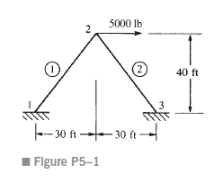
For the rigid frame shown in Figure P5-1, determine (1) the displacement components and the rotation at node 2, (2) the support reactions, and (3) the forces in each element. Then check equilibrium at node 2. Let E = 30 × 106 psi, A = 10 in2, and I = 500 in4 for both elements.
Solve the structures in Figures P5-16 through P5-18 by using substructuring.Figure P5-16 (Substructure the truss at nodes 3 and 4)Figure P5-17 (Substructure the beam at node 3)Figure P5-18 (Substructure the frame at node 2)
For the rigid frame shown in Figure P5-19, determine (1) the nodal displacement components and (2) the support reactions. (3) Draw the shear force and bending moment diagrams. For all elements, let E = 30 × 106 psi, I = 200 in.4, and A = 10 in.2
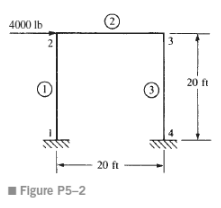
For the rigid frame shown in Figure P5-2, determine (1) the nodal displacement components and rotations, (2) the support reactions, and (3) the forces in each element. Let E = 30 × 106 psi, A = 10 in2, and I = 500 in4 for all elements.
For the rigid frame shown in Figure P5-20, determine (1) the nodal displacement components and (2) the support reactions. (3) Draw the shear force and bending moment diagrams. Let E = 30 × 106 psi, I = 200 in.4, and A = 10 in.2 for all elements, except as noted in the figure.
For the slant-legged rigid frame shown in Figure P5-21, size the structure for minimum weight based on a maximum bending stress of 20 ksi in the horizontal beam elements and a maximum compressive stress (due to bending and direct axial load) of 15 ksi in the slant-legged elements. Use the same
For the rigid building frame shown in Figure P5-22, determine the forces in each element and calculate the bending stresses. Assume all the vertical elements have A = 10 in.2 and I = 100 in.4 and all horizontal elements have A = 15 in.2 and I = 150 in.4 Let E = 29 × 106 psi for all elements. Let c
For the rigid frames or beams shown in Figures P5-23 through P5-38, determine the displacements and rotations at the nodes, the element forces, and the reactions.Figure P5-22Figure P5-23Figure P5-24Figure P5-25 Two bicycle frame models (coordinates shown in inches)Figure P5-26Figure P5-28Figure
Showing 7200 - 7300
of 7586
First
62
63
64
65
66
67
68
69
70
71
72
73
74
75
76
Step by Step Answers
.png)
-1.png)
-2.png)
-3.png)
.png)
.png)
.png)
-1.png)
-2.png)
![1 -1 =R V2 {V} = [K]{I} or I2](https://dsd5zvtm8ll6.cloudfront.net/si.question.images/image/images16/1414-P-T-H-T(1274)-1.png)
-2.png)
.png)
.png)
.png)
.png)
.png)
-1.png)
-2.png)
-3.png)
.png)
.png)
.png)
-1.png)
-2.png)
-3.png)
-1.png)
-2.png)
-1.png)
-2.png)
-1.png)
-2.png)
.png)
-1.png)
-2.png)
-3.png)
.png)
.png)
.png)
.png)
.png)
.png)
.png)
.png)
-1.png)
-2.png)
.png)
.png)
-1.png)
-2.png)
.png)
.png)
-1.png)
-2.png)
-1.png)
-2.png)
-1.png)
-2.png)
.png)
.png)
.png)
.png)
.png)
-1.png)
-2.png)
-3.png)
-1.png)
-2.png)
.png)
.png)
.png)
.png)
.png)
-1.png)
-2.png)
.png)
.png)
-1.png)
-2.png)
-3.png)
.png)
.png)
.png)
.png)
.png)
.png)
.png)
.png)
.png)
.png)
-1.png)
-2.png)
-3.png)
-1.png)
-2.png)
-3.png)
.png)
.png)
.png)
.png)
.png)
.png)
.png)
.png)
.png)
.png)
-1.png)
-2.png)
-3.png)
.png)
.png)
.png)
-1.png)
-2.png)
-3.png)
.png)
-1.png)
-2.png)
-3.png)
.png)
.png)
-1.png)
-2.png)
-3.png)

