New Semester
Started
Get
50% OFF
Study Help!
--h --m --s
Claim Now
Question Answers
Textbooks
Find textbooks, questions and answers
Oops, something went wrong!
Change your search query and then try again
S
Books
FREE
Study Help
Expert Questions
Accounting
General Management
Mathematics
Finance
Organizational Behaviour
Law
Physics
Operating System
Management Leadership
Sociology
Programming
Marketing
Database
Computer Network
Economics
Textbooks Solutions
Accounting
Managerial Accounting
Management Leadership
Cost Accounting
Statistics
Business Law
Corporate Finance
Finance
Economics
Auditing
Tutors
Online Tutors
Find a Tutor
Hire a Tutor
Become a Tutor
AI Tutor
AI Study Planner
NEW
Sell Books
Search
Search
Sign In
Register
study help
physics
thermodynamics
A First Course in the Finite Element Method 6th edition Daryl L. Logan - Solutions
A steel hole punch is shown in Figure P9-25a. Investigate the proper material for a hole punch. Tell me what material you used and why? Model the punch without the side groove (Figure P9-25b) and with the side groove (Figure P9-25c). Determine the von Mises stress distribution throughout the punch
A simplified model of a flywheel as shown in Figure P9-27 is considered as a uniform thin disk with center hole for mounting on a shaft. Assume the flywheel with inner radius of hole of 1 inch and outer radius of the flywheel of 4 inches. Assume the flywheel is made of 1045 high carbon steel. The
For an element of an axisymmetric body rotating with a constant angular velocity ω = 20 rpm as shown in Figure P9-3, evaluate the body-force matrix. The coordinates of the element are shown in the figure. Let the weight density (w be 0.283 lb / in3?Figure P9-3
For the axisymmetric elements shown in Figure P9-4, determine the element stresses. Let E = 15 × 106 psi and v = 0.25. The coordinates (in inches) are shown in the figures, and the nodal displacements for each element are u1 = 0.0001 in., w1 = 0.0002 in., u2 = 0.0005 in., w2 = 0.0003 in., u3 =
Explicitly show that the integration of Eq. (9.1.35) yields the j surface forces given by Eq. (9.1.36)?
For the elements shown in Figure P9-6, evaluate the stiffness matrices using Eq. (9.2.2). The coordinates (in millimeters) are shown in the figures. Let E = 105 GPa and v = 0.25 for each element.Figure P4-4(a)(b)
For the axisymmetric elements shown in Figure P9-7, determine the element stresses. Let E = 105 GPa and v = 0.25. The coordinates (in millimeters) are shown in the figures, and the nodal displacements for each element areu1 = 0.05 mm w1 = 0.03 mmu2 = 0.01 mm w2 = 0.01 mmu3 = 0.0 mm w3 = 0.0
Can we connect plane stress elements with axisymmetric ones? Explain.
Is the three-noded triangular element considered in Section 9.1 a constant strain element? Why or why not?
For the three-noded linear strain bar with three coordinates of nodes x1, x2, and x3, shown in Figure P10-1 in the global-coordinate system show that the Jacobian determinate is | [J] | 5L / 2Figure P10-1
Show that for the quadrilateral element described in Section 10.2, [J] can be expressed as
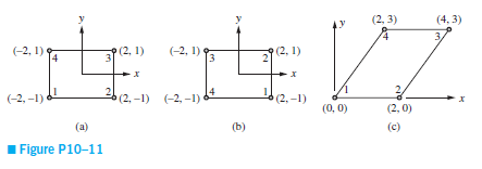
Determine the Jacobian matrix [J] and its determinant for the elements shown in Figure P10-11. Show that the determinant of [J] for rectangular and parallelogram shaped elements is equal to A / 4, where A is the physical area of the element and 4 actually represents the area of the rectangle of
Derive Eq. (10.2.18) with [Bi] given by Eq. (10.2.19) by substituting Eq. (10.2.16) for [D'] and Eqs. (10.2.5) for the shape functions into Eq. (10.2.17).
Use Eq. (10.2.30) with ps = 0 and pt = p (a constant) alongside 3-4 of the element shown in Figure 10-5 on page 500 to obtain the nodal forces?Figure P10-5(a)(b)
For the element shown in Figure P10-14, replace the distributed load with the energy equivalent nodal forces by evaluating a force matrix similar to Eq. (10.2.29). Let h 5 0.1 in thick. The global coordinates (in inches) are shown in Figure P10-14.Figure P10-14(a)(b)
Use Gaussian quadature with two and three Gauss points and Table 10-2 to evaluate the following integrals:(a)(b)(c)(d)(e)(f)(g)Then use the Newton-Cotes quadrature with two and three sampling points and Table 10-1 to evaluate the same integrals. Compare your results.
For the quadrilateral elements shown in Figure P10-16, write a computer program to evaluate the stiffness matrices using four-point Gaussian quadrature as outlined in Section 10.4. Let E = 30 × 106 psi and y = 0.25. The global coordinates (in inches) are shown in the figures.Figure P10-16(a)(b)
Evaluate the matrix [B] for the quadratic quadrilateral element shown in Figure 10-18 on page 523 (Section 10.5).Figure 10-18 Quadratic (Q8) isoparametric element
For the two-noded one-dimensional isoparametric element shown in Figure P10-2 (a) and (b), with shape functions given by Eq. (10.1.5), determine(a) Intrinsic coordinate s at point A and(b) Shape functions N1 and N2 at point A. If the displacements at nodes one and two are respectively, u1 = 0.005
For the three-noded bar (Figure P10-1), what Gaussian quadrature rule (how many Gauss points) would you recommend to evaluate the stiffness matrix? Why?Figure 10-10 Gaussian quadrature using two sampling points
Compare the Q4 and Q6 elements. What property makes the Q6 element better in modeling beam bending? What is the weakness of the Q6 element that is not inherent in the Q4 element?
Compare the Q4 and Q8 elements. What makes the Q8 a better element to model beam bending?
Answer the same questions as posed in problem 10.2 with the data listed under the Figure P10-3.Data from Problem 10.2For the two-noded one-dimensional isoparametric element shown in Figure P10–2 (a) and (b), with shape functions given by Eq. (10.1.5), determine(a) Intrinsic coordinate s at point
For the four-noded bar element in Figure P10-4, show that the Jacobian determinate is |[J]| = L / 2. Also determine the shape functions N1 - N4 and the strain/displacement matrix [B]. Assume u = α1 + α2s + α3s2 + α4s3.Figure P10-4
Using the three-noded bar element shown in Figure P10-5 (a) and (b), with shape functions given by Eq. (10.5.9), determine(a) The intrinsic coordinate s at point A and(b) The shape functions, N1, N2, and N3 at A. For the displacements of the nodes shown in Figure P10-5, determine(c) The
Using the three-noded bar element shown in Figure P10-5 (a) and (b), with shape functions given by Eq. (10.5.9), determine(a) The intrinsic coordinate s at point A and(b) The shape functions, N1, N2, and N3 at point A. For the displacements of the nodes shown in Figure P10-6, determine(c) The
Use the three-noded bar element and find the axial displacement at the end of the rod shown in Figure P10-8. Determine the stress at x = 0, x = L / 2 and x = L. Let A = 2 × 10⁻⁴ m2, E = 205 GPa, and L = 4 m. Use Eq. (10.5.22) for the element stiffness matrix.Figure P10-8
Derive |[J]| given by Eq. (10.2.22) for a four-noded isoparametric quadrilateral element?
Evaluate the matrix [B] for the tetrahedral solid element shown in Figure P11-1.Figure P11-1(a)(b)
Figure P11-10 shows how solid and plane elements may be connected. What restriction must be placed on the externally applied loads for this connection to be acceptable?Figure P11-10,
Express the explicit shape functions N2 through N8, similar to N1 given by Eq. (11.3.4), for the linear hexahedral element shown in Figure 11-5 on page 548.Figure P11-5Figure 11-5 Linear hexahedral element(a) In a global-coordinate system and(b) Element mapped into a cube of two unit sides placed
Express the explicit shape functions for the corner nodes of the quadratic hexahedral element shown in Figure 11-6 on page 551.Figure P11-6,(a)(b)
Determine the deflections at the four corners of the free end of the structural steel cantilever beam shown in Figure P11-14. Also determine the maximum principal stress. Compare your answer for deflections to the classical beam theory equation (( = PL3 / (3EI)).Figure P11-14
A portion of a structural steel brake pedal in a vehicle is modeled as shown in Figure P11-15. Determine the maximum deflection at the pedal under a uniform pressure acting over the pedal totaling 100 N.Figure P11-15
For the crane hook shown in Figure P11-16, determine the largest displacement and the maximum von Mises stress and where this value is located on the hook. Use AISI 4130 steel with yield strength of 66.7 ksi, modulus of elasticity of 30 × 103 ksi, and Poisson's ratio of 0.3. The total load of
An S-shaped block used in force measurement as shown in Figure P11-17 is to be designed for a pressure of 1000 psi applied uniformly to the top surface. Determine the uniform thickness of the block needed such that the sensor is compressed no more than 0.05 in. Also make sure that the maximum
A device is to be hydraulically loaded to resist an upward pressure P = 600 psi as shown in Figure P11-18. Determine the thickness of the device such that the maximum deflection is 0.1 in. vertically and the maximum stress is less than the yield strength using a factor of safety of 2 (only on the
An "Allen" wrench is used to loosen a bolt that has a hex-head cross section. As shown in Figure P11-19. This wrench is a 5 mm size and is made of quenched and tempered carbon steel with modulus of elasticity of 200 GPa, Poisson's ratio of 0.29, and yield strength of 615 MPa. The wrench is used to
Evaluate the stiffness matrix for the elements shown in Figure P11-1. Let E = 10 × 106 psi and v = 0.3.Figure P11-1,(a)(b)
A blacksmith desires to forge a work piece using the anvil shown in Figure P11-20. The anvil is bolted to a workbench with 4-1/2 in. diameter bolts. The anvil is made of gray cast iron with E = 15 × 103 ksi and v = 0.21. The tensile and compressive strengths are 31 ksi and 109 ksi, respectively. A
A fork from a forklift is constrained by two bars (not shown) that fit into each L-shaped appendage on the vertical part of the fork as shown in Figure P11-21. The fork is made of AISI 4130 steel with E = 206.84 GPa, v = 0.30, and a yield strength of 360 MPa . The fork is loaded with 46,189 N/m2 of
A radio-control car front steering unit is shown in Figure P11-22. The arm is made of molded ABS plastic with a modulus of elasticity of 362,000 psi and a tensile strength of 6000 psi. The base of the steering unit is attached to the frame of the car by bolts, so the three holes that the bolts pass
The hitch shown in Figure P11-23 is used on an International 496 disk. The hitch is made of cold drawn 1018 steel with E = 29 × 106 psi and v = 0.30. The yield strength of the material is 53,700 psi. The disk requires 200 hp to pull at 6 mph. The total force of 12,500 lbf in the hitch
A swivel C bracket shown in Figure P11-24 is mounted to a ceiling of a building and has a speaker (not shown) of 30 lbf hanging from each mounting hole. The mounting bracket is made of A 36 steel with a modulus of elasticity of 29 × 106 psi, Poisson's ratio of 0.29, and yield strength
The lower arms of a front-end loader are shown in Figure P11-25. The loader material is AISI 1010 cold drawn steel with a modulus of elasticity of 29.7 × 10⁶ psi and Poisson's ratio of 0.29. The yield strength of the material is 44,200 psi. In the finite element model, the back faces
A bicycle stem is shown in Figure P11-26. The stem attaches the handlebars to the steerer tube of the fork. The stem is made of 7075-T6 aluminum alloy with yield strength of 504 MPa. The load of 1200 N is spread over the mounting surface to the handlebar in the x - y plane and acts at a 45o angle
A solid part shown in Figure P11-28 is made to locate parts into proper position. The material is AISI 1005 steel with E = 200 GPa and v = 0.29. The front faces are fixed, and a pressure P of 100 MPa is applied to the semi-circular face of the inside slot, as shown in the figure. Determine the
For the elements shown in Figure P11-1, assume the nodal displacements have been determined to beDetermine the strains and then the stresses in the elements. Let E = 10 × 106 psi and v = 0.3?Figure P11-1,(a)(b)
What is special about the strains and stresses in the tetrahedral element?
Show that for constant body force Zb acting on an element (Xb = 0 and Yb = 0),Where {fbi} represents the body forces at node i of the element with volume V?
Evaluate the [B] matrix for the tetrahedral solid element shown in Figure P11-6. The coordinates are in units of millimeters?Figure P11-6,(a)(b)
Evaluate the stiffness matrix for the elements shown in Figure P11-6. Let E = 100 GPa and v = 0.3?Figure P11-6,(a)(b)
For the elements shown in Figure P11-6, assume the nodal displacements have been determined to beDetermine the strains and then the stresses in the elements. Let E = 100 GPa and v = 0.3?Figure P11-6,(a)(b)
For the linear strain tetrahedral element shown in Figure P11-9, (a) express the displacement fields u, v, and w in the x, y and z directions, respectively. There are 10 nodes each with three translational degrees of freedom, ui, vi, and wi. Also look at the linear strain triangle given by Eq.
A square steel plate (Figure P12-1) of dimensions 20 in. 3 20 in. with thickness of 0.1 in. is clamped all around. The plate is subjected to a uniformly distributed loading of 1 lb/in2. Using a 2 × 2 mesh and then a 4 × 4 mesh, determine the maximum deflection and maximum stress in the
A square steel plate 2 m × 2 m and 10 mm thick at the bottom of a tank must support salt water at a height of 3 m, as shown in Figure P12-11. Assume the plate to be built in (fixed all around). The plate allowable stress is 100 MPa. Let E = 200 GPa, v = 0.3 for the steel properties.
A stockroom floor carries a uniform load of p = 80 lb / ft2 over half the floor as shown in Figure P12-12. The floor has opposite edges clamped and remaining edges and midspan simply supported. The dimensions are 10 ft by 20 ft. The floor thickness is 4 in. The floor is made of reinforced concrete
A computer case shown in Figure P12-13 is made of AISI 4130 steel. The top surface is subjected to a uniform pressure load of 0.1 psi. The thickness of the case is uniformly 0.125 in. The bottom surface is fully constrained. Model the case using plate bending elements. Determine the maximum von
A manure spreader tank is shown in Figure P12-15. The tank is 90 in. long. The bottom axle is 12 in. long measured along the tank axis direction and located in the middle. The single front end coupling is 6 in. in length measured along the axis of the tank. The pressure is a variable surface
A tractor bucket with dimensions is shown in Figure P12-16. The load on the bucket is 600 lb spread uniformly over the inside surface. Three split surfaces are fully constrained. The bucket material is A36 structural steel. Determine the von Mises stress throughout the bucket. (This problem was
An L-shaped plate (Figure P12-2) with thickness 0.1 in. is made of ASTM A-36 steel. Determine the deflection under the load and the maximum principal stress and its location using the plate element. Then model the plate as a grid with two beam elements with each beam having the stiffness of each
A square (Figure P12-3) simply supported 20 in. × 20 in. steel plate with thickness 0.15 in. has a round hole of 4 in. diameter drilled through its center. The plate is uniformly loaded with a load of 5 lb/in2. Determine the maximum principal stress in the plate.Figure P12-3
A C-channel section (Figure P12-4) structural steel beam of 2-in. wide flanges, 3 in. depth and thickness of both flanges and web of 0.25 in. is loaded as shown with 100 lb acting in the y direction on the free end. Determine the free end deflection and angle of twist. Now move the load in the z
For the simply supported structural steel W 14 3 61 wide flange beam shown in Figure P12-5, compare the plate element model results with the classical beam bending results for deflection and bending stress. The beam is subjected to a central vertical load of 22 kip. The cross-sectional area is 17.9
For the structural steel plate structure shown in Figure P12-6, determine the maximum principal stress and its location. If the stresses are unacceptably high, recommend any design changes. The initial thickness of each plate is 0.25 in. The left and right edges are simply supported. The load is a
Design a steel box structure (Figure P12-7) 4 ft wide × 8 ft long made of plates to be used to protect construction workers while working in a trench. That is, determine a recommended thickness of each plate. The depth of the structure must be 8 ft. Assume the loading is from a side load acting
Determine the maximum deflection and maximum principal stress of the circular plate shown in Figure P12-8. The plate is subjected to a uniform pressure p = 50 kPa and fixed along its outer edge. Let E = 200 GPa, v = 0.3, radius r = 500 mm, and thickness t = 20 mm.Figure P12-8
Determine the maximum deflection and maximum principal stress for the plate shown in Figure P12-9. The plate is fixed along all three sides. A uniform pressure of 100 MPa is applied to the surface. The plate is made of steel with E = 200 GPa, v = 0.3, and thickness t = 10 mm, α =
For the one-dimensional composite bar shown in Figure P13-1, determine the interface temperatures. For element 1, let Kxx = 200 W/(m ( oC); for element 2, let Kxx = 100 W/(m ( oC); and for element 3, let Kxx = 50 W/(m ( oC). Let A = 0.1 m2. The left end has a constant temperature of 100 oC, and the
For the composite wall of a house, shown in Figure P13-10, determine the temperatures at the inner and outer surfaces and at the interfaces. The wall is composed of 2.5 cm thick plaster wall (k = 0.20 W/m-oC) on the inside, a 9 cm thick layer of fiberglass insulation (k = 0.038 W/m-oC), and a 1.25
Condensing steam is used to maintain a room at 20 oC. The steam flows through pipes that keep the pipe surface at 100 oC. To increase heat transfer from the pipes, stainless steel fins (k = 15 W/m-oC), 20 cm long and 0.5 cm in diameter, are welded to the pipe surface as shown in Figure P13-11. A
A tapered aluminum fin (k = 200 W/m-oC), shown in Figure P13-12, has a circular cross section with base diameter of 1 cm and tip diameter of 0.5 cm. The base is maintained at 200 oC and looses heat by convection to the surroundings at T( = 10 oC, h = 150 W/m2 -oC. The tip of the fin is insulated.
A wall is constructed of an outer layer of 0.5 inch thick plywood (k = 0.80 Btu/h-ft-oF), an inner core of 5 inch thick fiberglass insulation (k = 0.020 Btu/h-ft-oF), and an inner layer of 0.5 inch thick sheetrock (k = 0.10 Btu/h-ft-8F) (Figure P13-13). The inside temperature is 70 oF with h 51.5
The base plate of an iron is 0.6 cm thick. The plate is subjected to 100 W of power (provided by resistance heaters inside the iron, as shown in Figure P13-15), over a base plate cross-sectional area of 250 cm2, resulting in a uniform flux generated on the inside surface. The thermal conductivity
A hot surface is cooled by attaching fins (called pin fins) to it, as shown in Figure P13-16. The surface of the plate (left end of the pin) is 90 oC. The fins are 6 cm long and have a cross-sectional area of 5 × 10⁻⁶ m2 with a perimeter of 0.006 m. The fins are made of copper (k = 400
Use the direct method to derive the element equations for the one-dimensional steady-state conduction heat-transfer problem shown in Figure P13-17. The bar is insulated all around and has cross-sectional area A, length L, and thermal conductivity Kxx. Determine the relationship between nodal
Express the stiffness matrix and the force matrix for convection from the left end of a bar, as shown in Figure P13-18. Let the cross-sectional area of the bar be A, the convection coefficient be h, and the free stream temperature be T(.Figure P13-18
For the element shown in Figure P13-19, determine the [k] and {f} matrices. The conductivities are Kxx = Kyy 510 Btu / (h-ft-oF) and the convection coefficient is h = 20 Btu/(h-ft2 -oF). Convection occurs across the i-j surface. The free-stream temperature is T( = 70 oF. The coordinates are
For the one-dimensional rod shown in Figure P13-2 (insulated except at the ends), determine the temperatures at L/3, 2L/3, and L. Let Kxx = 6 Btu / (h.-in.-oF), h = 1.0 Btu / (h-in2 -oF), and T( = 0 oF. The temperature at the left end is 200 oF.Figure P13-2
Calculate the [k] and {f} matrices for the element shown in Figure P13-20. The conductivities are Kxx = Kyy = 10 W/(m ( oC) and the convection coefficient is h = 20 W/(m2 ( oC). Convection occurs across the i-m surface. The free-stream temperature is T( = 15oC. The coordinates are shown expressed
For the square two-dimensional body shown in Figure P13-21, determine the temperature distribution. Let Kxx = Kyy = 25 Btu / (h-ft-oF) and h = 10 Btu / (h-ft2 -oF). Convection occurs across side 4-5. The free-stream temperature is T( = 50 oF. The temperatures at nodes 1 and 2 are 100°F. The
For the square plate shown in Figure P13-22, determine the temperature distribution. Let Kxx = Kyy = 10 W/(m ( oC) and h = 20 W/(m2 ( oC). The temperature along the left side is maintained at 100 oC and that along the top side is maintained at 200oC.Figure P13-22
For the body shown in Figure P13-23, determine the temperature distribution. Surface temperatures are shown in the figure. The body is insulated along the top and bottom edges, and Kxx = Kyy = 1.0 Btu / (h-in.-oF). No internal heat generation is present.Figure P13-23Use a computer program to
For the square two-dimensional body shown in Figure P13-24, determine the temperature distribution. Let Kxx = Kyy 510 Btu / (h-ft-oF). The top surface is maintained at 400 oF and the other three sides are maintained at 50 oF. Also, plot the temperature contours on the body.Figure P13-24
For the square two-dimensional body shown in Figure P13-25, determine the temperature distribution. Let Kxx = Kyy = 10 Btu/(h-ft-oF) and h 510 Btu/(h-ft2 -oF). The top face is maintained at 400 oF, the left face is maintained at 50 oF, and the other two faces are exposed to an environmental
Hot water pipes are located on 2.0-ft centers in a concrete slab with Kxx = Kyy = 0.80 Btu / (h-ft-oF), as shown in Figure P13-26. If the outside surfaces of the concrete are at 75oF and the water has an average temperature of 200 oF, determine the temperature distribution in the concrete slab.
The cross section of a tall chimney shown in Figure 13-27 has an inside surface temperature of 330 oF and an exterior temperature of 50 oF. The thermal conductivity is K = 0.5 Btu / (h-ft-oF). Determine the temperature distribution within the chimney per unit length.Figure P13-27
The square duct shown in Figure P13-28 carries hot gases such that its surface temperature is 570 oF. The duct is insulated by a layer of circular fiberglass that has a thermal conductivity of K = 0.020 Btu / (h-ft-oF). The outside surface temperature of the fiberglass is maintained at 70 oF.
The buried pipeline in Figure P13-29 transports oil with an average temperature of 60 oF. The pipe is located 15 ft below the surface of the earth. The thermal conductivity of the earth is 0.6 Btu / (h-ft-oF). The surface of the earth is 50 oF. Determine the temperature distribution in the
A rod with uniform cross-sectional area of 2 in2 and thermal conductivity of 3 Btu/(h-in.-oF) has heat flow in the x direction only (Figure P13-3). The right end is insulated. The left end is maintained at 50 oF, and the system has the linearly distributed heat flux shown.Use a two-element model
A 10-in.-thick concrete bridge deck is embedded with heating cables, as shown in Figure P13-30. If the lower surface is at 0 oF, the rate of heat generation (assumed to be the same in each cable) is 100 Btu / (h-in.) and the top surface of the concrete is at 35oF. The thermal conductivity of the
For the circular body with holes shown in Figure P13-31, determine the temperature distribution. The inside surfaces of the holes have temperatures of 200 oC. The outside of the circular body has a temperature of 20 oC. Let Kxx = Kyy = 10 W / (m ( oC).Figure P13-31,
For the square two-dimensional body shown in Figure P13-32, determine the temperature distribution. Let Kxx = Kyy = 5 W / (m ( oC) and h = 10 W / (m2 ( oC). The top face is maintained at 100 oC, the left face is maintained at 0 oC, and the other two faces are exposed to a free-stream temperature of
For the two-dimensional body shown in Figure P13-34, determine the temperature distribution. Let the left and right ends have constant temperatures of 200 oC and 0 oC, respectively. Let Kxx = Kyy = 5 W / (m ( oC). The body is insulated along the top and bottom.Figure P13-34
For the two-dimensional body shown in Figure P13-35, determine the temperature distribution. The top and bottom sides are insulated. The left side has a constant temperature of 100 8C. The right side is subjected to heat transfer by convection. Let Kxx = Kyy = 10 W / (m ( oC).Figure P13-35
For the two-dimensional body shown in Figure P13-36, determine the temperature distribution. The left and right sides are insulated. The top surface is subjected to heat transfer by convection. The bottom and internal portion surfaces are maintained at 300 oC.Figure P13-36
Determine the temperature distribution and rate of heat flow through the plain carbon steel ingot shown in Figure P13-37. Let k = 60 W/m-K) for the steel. The top surface is held at 60 oC, while the underside surface is held at 10 oC. Assume that no heat is lost from the sides.Figure P13-37
Determine the temperature distribution and rate of heat flow per foot length from a 5 cm outer diameter pipe at 180 oC placed eccentrically within a larger cylinder of insulation (k = 0.058 W/m-oC) as shown in Figure P13-38. The diameter of the outside cylinder is 15 cm, and the surface temperature
Determine the temperature distribution and rate of heat flow in the molded foam insulation (k = 0.17 Btu/h-ft-oF) shown in Figure P13-39.Figure P13-39,
The rod of 1-in. radius shown in Figure P13-4 generates heat internally at the rate of uniform Q = 5000 Btu/(h-ft3 ) throughout the rod. The left edge and perimeter of the rod are insulated, and the right edge is exposed to an environment of Tx = 50 oF. The convection heat-transfer coefficient
Showing 7400 - 7500
of 7586
First
62
63
64
65
66
67
68
69
70
71
72
73
74
75
76
Step by Step Answers
.png)
.png)
.png)
-1.png)
-2.png)
-3.png)
-1.png)
-2.png)
-3.png)
-1.png)
-2.png)
-3.png)
.png)
![XI У N1,5 N2,5 N3, s [J] = N1,1 N2.1 N3,1 N4.5 || x2 y2 N4.1 Хз Уз](https://dsd5zvtm8ll6.cloudfront.net/si.question.images/image/images16/1414-P-T-H-T(1478).png)
.png)
-1.png)
-2.png)
-1.png)
-2.png)
-1.png)
-2.png)
.png)
-1.png)
-2.png)
.png)
-1.png)
-2.png)
.png)
-1.png)
-2.png)
-1.png)
-2.png)
.png)
-1.png)
-2.png)
.png)
-1.png)
-2.png)
-1.png)
-2.png)
.png)
.png)
-1.png)
-2.png)
.png)
.png)
-1.png)
-2.png)
-3.png)
-1.png)
-2.png)
-1.png)
-2.png)
-3.png)
-1.png)
-2.png)
-3.png)
-1.png)
-2.png)
-3.png)
-1.png)
-2.png)
-1.png)
-2.png)
-3.png)
-1.png)
-2.png)
.png)
-1.png)
-2.png)
-1.png)
-2.png)
-3.png)
.png)
-1.png)
-2.png)
-1.png)
-2.png)
-1.png)
-2.png)
-3.png)
.png)
.png)
.png)
.png)
.png)
-1.png)
-2.png)
-1.png)
-2.png)
.png)
.png)
.png)
.png)
.png)
.png)
.png)
.png)
.png)
.png)
.png)
.png)
.png)
.png)
.png)
.png)
.png)
.png)
.png)
.png)
.png)
.png)
.png)
.png)
.png)
.png)
.png)
.png)
.png)
.png)
.png)
.png)
.png)
.png)
.png)
.png)
.png)
.png)
.png)
.png)

