New Semester
Started
Get
50% OFF
Study Help!
--h --m --s
Claim Now
Question Answers
Textbooks
Find textbooks, questions and answers
Oops, something went wrong!
Change your search query and then try again
S
Books
FREE
Study Help
Expert Questions
Accounting
General Management
Mathematics
Finance
Organizational Behaviour
Law
Physics
Operating System
Management Leadership
Sociology
Programming
Marketing
Database
Computer Network
Economics
Textbooks Solutions
Accounting
Managerial Accounting
Management Leadership
Cost Accounting
Statistics
Business Law
Corporate Finance
Finance
Economics
Auditing
Tutors
Online Tutors
Find a Tutor
Hire a Tutor
Become a Tutor
AI Tutor
AI Study Planner
NEW
Sell Books
Search
Search
Sign In
Register
study help
physics
thermodynamics
A First Course in the Finite Element Method 6th edition Daryl L. Logan - Solutions
For the rigid stairway frame shown in Figure P5-3, determine (1) the displacements at node 2, (2) the support reactions, and (3) the local nodal forces acting on each element. Draw the bending moment diagram for the whole frame. Remember that the angle between elements 1 and 2 is preserved as
Consider the plane structure shown in Figure P5-39. First assume the structure to be a plane frame with rigid joints, and analyze using a frame element. Then assume the structure to be pin-jointed and analyze as a plane truss, using a truss element. If the structure is actually a truss, is it
For the rigid frame shown in Figure P5-4, determine (1) the nodal displacements and rotation at node 4, (2) the reactions, and (3) the forces in each element. Then check equilibrium at node 4. Finally, draw the shear force and bending moment diagrams for each element. Let E = 30 × 103
For the two-story, two-bay rigid frame shown in Figure P5-40, determine (1) the nodal displacement components and (2) the shear force and bending moments in each member. Let E = 200 GPa, I = 2 × 10⁻⁴ m4 for each horizontal member and I = 1.5 × 10⁻⁴ m4 for each vertical
For the two-story, three-bay rigid frame shown in Figure P5-41, determine (1) the nodal displacements and (2) the member end shear forces and bending moments. (3) Draw the shear force and bending moment diagrams for each member. Let E = 200 GPa, I = 1.29 × 10⁻⁴ m4 for the beams and I =
For the rigid frame shown in Figure P5-42, determine (1) the nodal displacements and rotations and (2) the member shear forces and bending moments. Let E = 200 GPa, I = 0.795 × 10⁻⁴m4 for the horizontal members, and I = 0.316 × 10⁻⁴ m4 for the vertical members. These I
For the rigid frame shown in Figure P5-43, determine (1) the nodal displacements and rotations and (2) the shear force and bending moments in each member. Let E = 29 × 106 psi, I = 3100 in.4 for the horizontal members and I = 1100 in.4 for the vertical members. The I values correspond
A structure is fabricated by welding together three lengths of I-shaped members as shown in Figure P5-44. The yield strength of the members is 36 ksi, E = 29 × 106 psi, and Poisson's ratio is 0.3. The members all have cross-section properties corresponding to a W 18 × 76. That is, A = 22.3 in.2,
For the tapered beam shown in Figure P5-45, determine the maximum deflection using one, two, four, and eight elements. Calculate the moment of inertia at the midlength station for each element. Let E = 30 × 106 psi, I0 100 in I = 4, and L = 100 in. Run cases where n = 1, 3, and 7. Use a beam
Derive the stiffness matrix for the nonprismatic torsion bar shown in Figure P5-46. The radius of the shaft is given by r = r0 + (x /L)r0, where r0 is the radius at x = 0.
Derive the total potential energy for the prismatic circular cross-section torsion bar shown in Figure P5-47. Also determine the equivalent nodal torques for the bar subjected to uniform torque per unit length (lb-in./in.). Let G be the shear modulus and J be the polar moment of inertia of the bar.
For the grid shown in Figure P5-48, determine the nodal displacements and the local element forces. Let E = 30 × 106 psi, G = 12 × 106 psi, I = 200 in.4, and J = 100 in.4 for both elements.
For the rigid frames shown in Figures P5-5 through P5-15, determine the displacements and rotations of the nodes, the element forces, and the reactions. The values of E, A, and I to be used are listed next to each figure.Figure P5-5Figure P5-6 Figure P5-7 Figure P5-8 Figure P5-9 Figure P5-10 Figure
For the grids shown in Figures P5-50 and P5-51, determine the nodal displacements and the local element forces. Let E = 210 GPa, G = 84 GPa, I = 2 × 10⁻⁴m4, J = 1310-4 m4, and A = 1310-2m2.
Solve the grid structures shown in Figures P5-52 through P5-57 using a computer program. For grids P5-52-P5-54, let E = 30 × 106 psi, G = 12 × 106 psi, I = 200 in.4, and J = 100 in.4, except as noted in the figures. In Figure P5-54, let the cross elements have I = 50 in.4
Determine the displacements and reactions for the space frames shown in Figures P5-58 and P5-59. Let Ix = 100 in.4, Iy = 200 in.4, Iz = 1000 in.4, E = 30,000 ksi, G = 12,000 ksi, and A = 100 in.2 for both frames.1.2.
Design a jib crane as shown in Figure P5-60 that will support a downward load of 6000 lb. Choose a common structural steel shape for all members. Use allowable stresses of 0.66Sy (Sy is the yield strength of the material) in bending, and 0.60Sy in tension on gross areas. The maximum deflection
Design the support members AB and CD for the platform lift shown in Figure P5-61. Select a mild steel and choose suitable cross-sectional shapes with no more than a 4 : 1 ratio of moments of inertia between the two principal directions of the cross section. You may choose two different cross
A two-story building frame is to be designed as shown in Figure P5-62. The members are all to be I-beams with rigid connections. We would like the floor joists beams to have a 15-in. depth and the columns to have a 10 in. width. The material is to be A36 structural steel. Two horizontal loads and
A pulpwood loader as shown in Figure P5-63 is to be designed to lift 2.5 kip. Select a steel and determine a suitable tubular cross section for the main upright member BF that has attachments for the hydraulic cylinder actuators AE and DG. Select a steel and determine a suitable box section for the
A small hydraulic floor crane as shown in Figure P5-65 carries a 5000-lb load. Determine the size of the beam and column needed. Select either a standard box section or a wide-flange section. Assume a rigid connection between the beam and column. The column is rigidly connected to the floor. The
Design the gabled frame subjected to the external wind load shown in Figure P5-68 (comparable to an 80 mph wind speed) for an industrial building. Assume this is one of a typical frame spaced every 20 feet. Select a wide flange section based on allowable bending stress of 20 ksi and an allowable
Design the gabled frame shown for a balanced snow load shown in Figure P5-69 (typical of the Midwest) for an apartment building. Select a wide flange section for the frame. Assume the allowable bending stress not to exceed 140 MPa. Use ASTM A36 steel.
Design a gantry crane that must be able to lift 10 tons as it must lift compressors, motors, heat exchangers, and controls. This load should be placed at the center of one of the main 12-foot-long beams as shown in Figure P5-70, by the hoisting device location. Note that this beam is on one side of
Design the rigid highway bridge frame structure shown in Figure P5-71 for a moving truck load (shown below) simulating a truck moving across the bridge. Use the load shown and place it along the top girder at various locations. Use the allowable stresses in bending and compression and allowable
The curved semi-circular frame shown in Figure P5-73 is supported by a pin on the left end and a roller on the right end and is subjected to a load P 51000 lb at its apex. The frame has a radius to centerline cross section of R = 120 in. Select a structural steel W shape from Appendix F such that
Sketch the variations of the shape functions Nj and Nm, given by Eqs. (6.2.18), over the surface of the triangular element with nodes i, j, and m. Check that Ni 1Nj 1Nm 51 anywhere on the element.
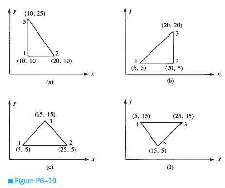
For the plane strain elements shown in Figure P6-10, the nodal displacements are given asu1 = 0.005 mm............v1 = 0.002 mm............u2 = 0.0 mmv2 = 0.0 mm...............u3 = 0.005 mm............v3 = 0.0 mmDetermine the element stresses sx, sy, xy, s1, and s2 and the principal angle u p. Let
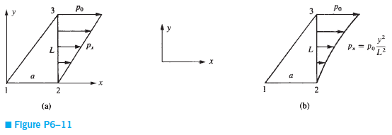
Determine the nodal forces for (1) a linearly varying pressure px on the edge of the triangular element shown in Figure P6-11(a); and (2) the quadratic varying pressure shown in Figure P6-11(b) by evaluating the surface integral given by Eq. (6.3.7). Assume the element thickness is equal to t.
Determine the nodal forces for (1) the quadratic varying pressure loading shown in Figure P6-12(a) and (2) the sinusoidal varying pressure loading shown in Figure P6-12(b) by the work equivalence method [use the surface integral expression given by Eq. (6.3.7)]. Assume the element thickness to be
Determine the nodal displacements and the element stresses, including principal stresses, for the thin plate of Section 6.5 with a uniform shear load (instead of a tensile load) acting on the right edge, as shown in Figure P6-13. Use E = 30 × 106 psi, v = 0.30, and t = 1 in.
Determine the nodal displacements and the element stresses, including principal stresses, due to the loads shown for the thin plates in Figure P6-14. Use E = 105 GPa, v = 0.30, and t = 5 mm. Assume plane stress conditions apply. The recommended discretized plates are shown in the figures. Use a
Determine the nodal displacements and the element stresses, including principal stresses, due to the loads shown for the thin plates in Figure P6-15 on the next page. Use E = 30 × 106 psi, v = 0.30, and t = 0.25 inches. Assume plane stress conditions apply. The recommended discretized plates
Evaluate the body force matrix for the plates shown in Figures P6-14(a) and (c). Assume the weight density to be 154.2 kN/m3.
Why is the triangular stiffness matrix derived in Section 6.2 called a constant-strain triangle?
How do the stresses vary within the constant-strain triangle element?
Can you use the plane stress or plane strain element to model the following? If so, indicate which ones are best modeled using plane stress or best modeled using plane strain elements.a. A flat slab floor of a building with vertical loading perpendicular to the slabb. A uniform concrete dam
For a simple three-noded triangular element, show explicitly that differentiation of Eq. (6.2.47) indeed results in Eq. (6.2.48); that is, substitute the expression for [B] and the plane stress condition for [D] into Eq. (6.2.47), and then differentiate πp with respect to each nodal degree of
The plane stress element only allows for in-plane displacements, while the frame or beam element resists displacements and rotations. How can we combine the plane stress and beam elements and still ensure compatibility?
For the plane structures modeled by triangular elements shown in Figure P6-21, show that numbering in the direction that has fewer nodes, as in Figure P6-21(a) (as opposed to numbering in the direction that has more nodes), results in a reduced bandwidth. Illustrate this fact by filling in, with X
Go through the detailed steps to evaluate Eq. (6.3.6).In Eq. (6.3.6)
Show that the sum N1 + N2 + N3 + N4 is equal to 1 anywhere on a rectangular element, where N1 through N4 are defined by Eqs. (6.6.5).In Eqs (6.6.5)
For the rectangular element of Figure 6-20 on page 374 the nodal displacements are given byFor b = 2 in., h = 1 in., E = 30 × 106 psi, and v = 0.3, determine the element strains and stresses at the centroid of the element and at the corner nodes.
Evaluate the stiffness matrix for the elements shown in Figure P6-3. The coordinates are in units of inches. Assume plane stress conditions. Let E = 10 × 106 psi, v = 0.25, and thickness t = 1in.(a)(b)(c)
For the elements given in Problem 6.3, the nodal displacements are given asu1 = 0.0 in.............v1 = 0.0025 in.............u2 0.0012 in.v2 = 0.0 in.............u3 = 0.0 in...............v3 = 0.0025 in.Determine the element stresses σx, σy, τxy, σ1, and σ2 and the principal angle
Determine the von Mises stress for Problem 6.4.u1 = 0.0 in.............v1 = 0.0025 in.............u2 0.0012 in.v2 = 0.0 in.............u3 = 0.0 in...............v3 = 0.0025 in.Determine the element stresses σx, σy, τxy, σ1, and σ2 and the principal angle θp. Use the values of E,
Evaluate the stiffness matrix for the elements shown in Figure P6-6. The coordinates are given in units of millimeters. Assume plane stress conditions. Let E = 105 GPa, v = 0.25, and t = 10 mm.
For the elements given in Problem 6.6, the nodal displacements are given asu1 = 2.0 mm...............v1 = 1.0 mm............u2 = 0.5 mmv2 = 0.0 mm...............u3 = 3.0 mm.............v3 = 1.0 mm(a)(b)(c)Determine the element stresses σx, σy, τxy, σ1, and σ2 and the principal angle
Determine the von Mises stress for Problem 6.7.For the elements given in Problem 6.6, the nodal displacements are given asu1 = 2.0 mm...............v1 = 1.0 mm............u2 = 0.5 mmv2 = 0.0 mm...............u3 = 3.0 mm.............v3 = 1.0 mm(a)(b)(c)Determine the element stresses σx, σy,
For the plane strain elements shown in Figure P6-9, the nodal displacements are given asu1 = 0.001 in...............v1 = 0.005 in..............u3 = 0.001 in.v2 = 0.0025 in..............u3 = 0.0 in.....................v3 = 0.0in.Determine the element stresses σx, σy, τxy, σ1, and σ2
For the finite element mesh shown in Figure P7-1, comment on the appropriateness of the mesh. Indicate the mistakes in the model. Explain and show how to correct them.Figure P7-1
Consider the bar with two elements shown in Figure P7.10. Perform a patch test using these two elements. Let E = 200 GPa, and A = 1 × 10⁻⁴ m2. Use the standard bar element stiffness matrix [Eq. (3.1.14)] derived using the shape functions N1 (x) = x / L and N2 (x) = 1 - x/L.a. For the rigid body
Determine the free-end displacements and the element stresses for the plate discretized into four triangular elements and subjected to the tensile forces shown in Figure P7-12. Compare your results to the solution given in Section 6.5. Why are these results different? Let E = 30 × 106 psi, =
Determine the stresses in the plate with the hole subjected to the tensile stress shown in Figure P7-13. Graph the stress variation (x versus the distance y from the hole. Let E = 200 GPa, v = 0.25, and t = 25 mm. (Use various mesh densities, depending on your computer program in your finite
Solve the following problem of a steel tensile plate with a concentrated load applied at the top, as shown in Figure P7-14. Determine at what depth the effect of the load dies out. Plot stress (y versus distance from the load. At distances of 1 in., 2 in., 4 in., 6 in., 10 in., 15 in., 20 in., and
For the flat connecting rod shown in Figure P7-15, determine the maximum principal stresses and their location. Let E = 30 × 106 psi, v = 0.25, t = 1 in., and P = 1000 lb.Figure P7-15
Determine the maximum principal stresses and their locations for the member with fillet subjected to tensile surface tractions shown in Figure P7-16. Let E = 200 GPa and v = 0.25. Then let E = 73 GPa and v = 0.30. Let t = 25 mm for both cases. Compare your answers for the two cases.Figure P7-16
Determine the maximum principal stresses in the member with a re-entrant corner as shown in Figure P7-17. At what location are the principal stresses largest? Let E = 30 × 106 psi and v = 0.25. Use plane strain conditions.Figure P7-17
For the tooth implant subjected to loads shown in Figure P7-19, determine the maximum principal stresses. Let E = 1.6 × 10⁶ psi and v = 0.3 for the dental restorative implant material (cross-hatched), and let E = 1 × 10⁶ psi and v = 0.35 for the bony material. Let X = 0.05 in., 0.1 in., 0.2
Comment on the mesh sizing in Figure P7-2. Is it reasonable? If not, explain why not.Figure P7-2
Determine the middepth deflection at the free end and the maximum principal stresses and their location for the beam subjected to the shear load variation shown in Figure P7-20. Do this using 64 rectangular elements all of size 12 in. × 1/2 in.; then all of size 6 in. ×1 in.; then all of
Determine the stresses in the shear wall shown in Figure P7-21. At what location are the principal stresses largest? Let E = 21 GPa, v = 0.25, twall 5 0.10 m, and tbeam = 0.20 m. Use 0.1 m radii at the re-entrant corners.Figure P7-21
Determine the stresses in the plates with the round and square holes subjected to the tensile stresses shown in Figure P7-22. Compare the largest principal stresses for each plate. Let E = 210 GPa, v = 0.25, and t = 5 mm.Figure P7-22
For the concrete overpass structure shown in Figure P7-23, determine the maximum principal stresses and their locations. Assume plane strain conditions. Let E = 3.0 × 10⁶ psi and v = 0.30.Figure P7-23
For the tensile member shown in Figure P7-25 on the next page with two holes, determine the maximum principal stresses and their locations. Let E = 210 GPa, v = 0.25, and t = 10 mm. Then let E = 70 GPa and v = 0.30. Compare your results. Use 2 kN/m2 spread uniformly over the right side?Figure P7-25
For the plate shown in Figure P7-26 on the next page, determine the maximum von Mises stresses and their locations. Let E = 210 GPa and v = 0.25?Figure P7-26
Determine the von Mises stresses in the wrench shown in Figure P7-28. Let E = 200 GPa and v = 0.25, and assume uniform thickness t = 10 mm. Assume the bottom inside surface is fixed.Figure P7-28
What happens if the material property v = 0.5 in the plane strain case? Is this possible? Explain.
For the 1 in. thick canopy hook shown in Figure P7-31 on page 432, used to hold down an aircraft canopy, determine the maximum von Mises stress and maximum deflection. The hook is subjected to a concentrated upward load of 5000 lb as shown. Assume boundary conditions of fixed supports over the
For the ¼ in. thick L-shaped steel bracket shown in Figure P7-32 on page 432, show that the stress at the 90o re-entrant corner never converges. Try models with increasing numbers of elements to show this while plotting the maximum principal stress in the bracket. That is, start with one model,
The machine shown in Figure P7-33 on page 433 is an overload protection device that releases the load when the shear pin S fails. Determine the maximum von Mises stress in the upper part ABE if the pin shears when its shear stress is 40 MPa. Assume the upper part to have a uniform thickness of 6
One arm of a crimper tool shown in Figure P7-37 is to be designed of 1080 as-rolled steel. The loads are shown in the figure. Fix the nodes around the two holes. Select a thickness for the arm based on the material not yielding with a factor of safety of 1.5. Recommend any other changes in the
Design the bicycle wrench with the approximate dimensions shown in Figure P7-38. If you need to change dimensions explain why. The wrench should be made of steel or aluminum alloy. Determine the thickness needed based on the maximum distortion energy theory. Plot the deformed shape of the wrench
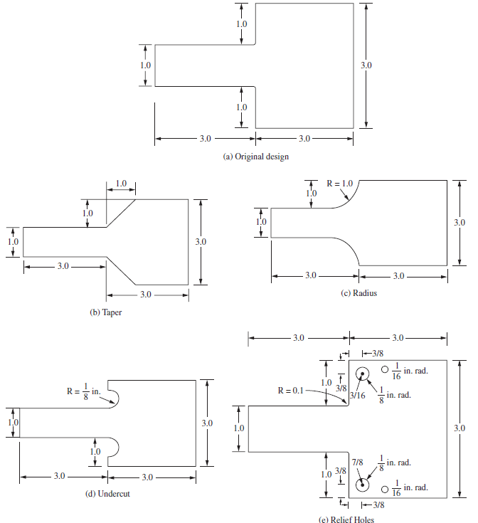
For the various parts shown in Figure P7-39 on the next page determine the best one to relieve stress. Make the original part have a small radius of 0.1 in. at the inside reentrant corners. Place a uniform pressure load of 1000 psi on the right end of each part and fix the left end. All units shown
Under what conditions is the structure in Figure P7-4 a plane strain problem? Under what conditions is the structure a plane stress problem?Figure P7-4
When do problems occur using the smoothing (averaging of stress at the nodes from elements connected to the node) method for obtaining stress results?
What thickness do you think is used in computer programs for plane strain problems?
Which one of the CST models shown in Figure P7-7 is expected to give the best results for a cantilever beam subjected to an end shear load? Why?Figure P7-7(a)
The plane stress element only has in-plane displacements, while the frame element resists displacements and rotations. How can we combine the plane stress and beam elements and still insure compatibility? That is, how can we make sure the frame element and plane stress element remain together?
In considering the patch test, answer the following questions:(a) Can elements of different mechanical properties be used? Why?(b) Can the patch be arbitrary in shape? Why?(c) Can we mix triangular and quadrilateral elements in the patch test?(d) Can we mix bar elements with triangular or
Evaluate the shape functions given by Eq. (8.2.6). Sketch the variation of each function over the surface of the triangular element shown in Figure 8-3?Figure 8-3 LST triangle for evaluation of a stiffness matrix
Express the strains εx, εy, and γxy for the element of Figure 8-3 by using the results given in Section 8.2. Evaluate these strains at the centroid of the element; then evaluate the stresses at the centroid in terms of E and v. Assume plane stress conditions apply?
For the element of Figure 8-3 (shown again as Figure P8-3) subjected to the uniform pressure shown acting over the vertical side, determine the nodal force replacement system using Eq. (6.3.7). Assume an element thickness of t.Figure P8-3
For the element of Figure 8-3 (shown as Figure P8-4) subjected to the linearly varying line load shown acting over the vertical side, determine the nodal force replacement system using Eq. (6.3.7). Compare this result to that of Problem 6.11. Are these results expected? Explain.Figure P8-3Figure
For the linear-strain elements shown in Figure P8-5, determine the strains (x, (y, and (xy. Evaluate the stresses (x, (y, and (xy at the centroids. The coordinates of the nodes are shown in units of inches. Let E = 30 × 106 psi, v = 0.25, and t = 0.25 in. for both elements. Assume plane stress
For the linear-strain element shown in Figure P8-6, determine the strains (x, (y, and (xy. Evaluate these strains at the centroid of the element; then evaluate the stresses (x, (y, and (xy at the centroid. The coordinates of the nodes are shown in units of millimeters. Let E = 210 GPa,v = 0.25, and
Evaluate the shape functions for the linear-strain triangle shown in Figure P8-7. Then evaluate the [B] matrix. Units are millimeters.Figure P8-7
For the elements shown in Figure P9-1, evaluate the stiffness matrices using Eq. (9.2.2). The coordinates are shown in the figures. Let E = 15 × 106 psi and v = 0.25 for each element.Figure P9-1(a)(b)(c)
How should one model the boundary conditions of nodes acting on the axis of symmetry?
How would you evaluate the circumferential strain, εθ, at r = 0? What is this strain in terms of the a's given in Eq. (9.1.15). Elasticity theory tells us that the radial strain must equal the circumferential strain at r = 0?
What will be the stresses σr and σθ at r = 0? Look at Eq. (9.1.2) after considering Problem 9.11.
The soil mass in Figure P9-13 is loaded by a force transmitted through a circular footing as shown. Determine the stresses in the soil. Compare the values of σr using an axisymmetric model with the σy values using a plane stress model. Let E = 3000 psi and v = 0.45 for the soil mass.Figure
Perform a stress analysis of the pressure vessel shown in Figure P9-14. Let E = 5 × 10⁶ psi and v = 0.15 for the concrete, and let E = 29 × 106 psi and v = 0.25 for the steel liner. The steel liner is 2 in. thick. Let the pressure p equal 500 psi. Use a 0.5 in. radius in the re-entrant
Perform a stress analysis of the concrete pressure vessel with the steel liner shown in Figure P9-15. Let E = 30 GPa and v = 0.15 for the concrete, and let E = 205 GPa and v = 0.25 for the steel liner. The steel liner is 50 mm thick. Let the pressure p equal 700 kPa. Use a 10 mm radius in the
For the axisymmetric connecting rod shown in Figure P9-18, determine the stresses σz, σr, σθ, and τrz. Plot stress contours (lines of constant stress) for each of the normal stresses. Let E = 30 × 106 psi and v = 0.25. The applied loading and boundary conditions are shown in the figure. A
For the thick-walled open-ended cylindrical pipe subjected to internal pressure shown in Figure P9-19, use five layers of elements to obtain the circumferential stress, σθ, and the principal stresses and maximum radial displacement. Compare these results to the exact circumferential stress and
Evaluate the nodal forces used to replace the linearly varying surface traction shown in Figure P9-2. Use Eq. (9.1.34).Figure P9-2
A steel cylindrical pressure vessel with flat plate end caps is shown in Figure P9-20 with vertical axis of symmetry. Addition of thickened sections helps to reduce stress concentrations in the corners. Analyze the design and identify the most critically stressed regions. Note that inside sharp
For the cylindrical vessel with ellipsoidal heads shown in Figure P9-22a under loading p = 500 psi, determine if the vessel is safe against yielding. Use the same material and factor of safety as in Problem 9.21. Now let a 5100 in., b = 50 in., and thickness t = 2 in. Which vessel has the lowest
The syringe with plunger is shown in Figure P9-23. The material of the syringe is glass with E = 69 GPa, v = 0.15, and tensile strength of 5 MPa. The bottom hole is assumed to be closed under test conditions. Determine the deformation and stresses in the glass. Compare the maximum principal stress
Showing 7300 - 7400
of 7586
First
62
63
64
65
66
67
68
69
70
71
72
73
74
75
76
Step by Step Answers
.png)
.png)
.png)
.png)
.png)
.png)
.png)
.png)
.png)
.png)
.png)
-1.png)
-2.png)
-3.png)
.png)
.png)
-1.png)
-2.png)
.png)
.png)
.png)
.png)
.png)
.png)
.png)
.png)
.png)
-1.png)
-2.png)
-3.png)
.png)
.png)
.png)
.png)
.png)
.png)
.png)
.png)
-1.png)
-2.png)
-3.png)
-1.png)
-2.png)
-3.png)
-1.png)
-2.png)
-3.png)
-1.png)
-2.png)
-3.png)
-1.png)
-2.png)
-3.png)
-1.png)
-2.png)
-3.png)
.png)
.png)
.png)
.png)
.png)
.png)
.png)
.png)
.png)
.png)
.png)
.png)
.png)
.png)
.png)
.png)
.png)
.png)
.png)
.png)
.png)
.png)
.png)
-1.png)
-2.png)
-3.png)
.png)
.png)
-1.png)
-2.png)
-1.png)
-2.png)
.png)
.png)
-1.png)
-2.png)
-3.png)
.png)
.png)
.png)
.png)
.png)
.png)
.png)
.png)

