

Question: Modify the CMFB schematic in Fig. 12.26 to inject currents at the drains of M 1 and M 2 , in a manner similar to
Fig. 12.26:
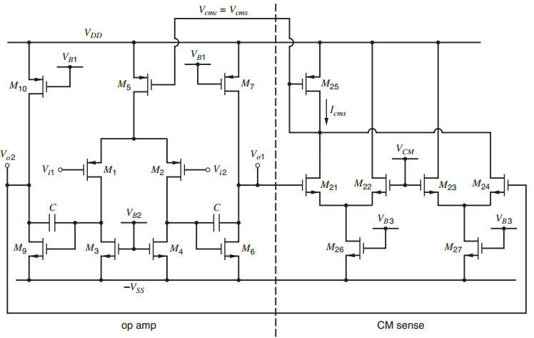
Fig. 12.18
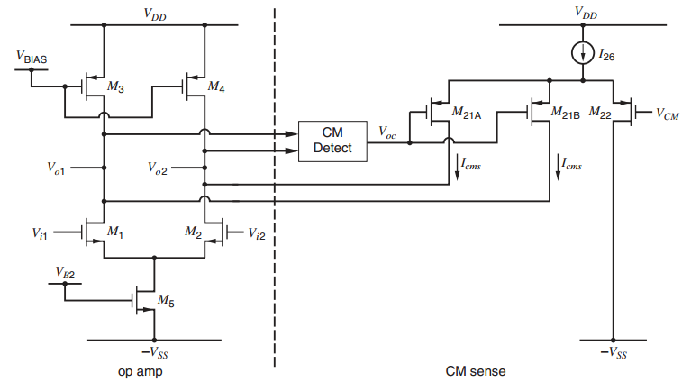
Veme = Vems VDD VB1 VB1 M25 M7 M5 M10 Iems V CM Vo1 V.2 Vi2 M24 M2 M23 M1 M22 Vi1 M21 VB3 V V82 M27 M26 M6 M M9 -V s CM sense op amp V DD VDD 126 VBIAS M4 21 22 V M21A Iems Detect \Lems Vo2 Vo1 M2 Vi2 M1 Vi1 VB2 M5 -Vss -Vss CM sense op amp
Step by Step Solution
★★★★★
3.35 Rating (164 Votes )
There are 3 Steps involved in it
1 Expert Approved Answer
Step: 1 Unlock

One solution MIQ 400MA Voz 4H M9 M5 200... View full answer
Question Has Been Solved by an Expert!
Get step-by-step solutions from verified subject matter experts
Step: 2 Unlock
Step: 3 Unlock