New Semester
Started
Get
50% OFF
Study Help!
--h --m --s
Claim Now
Question Answers
Textbooks
Find textbooks, questions and answers
Oops, something went wrong!
Change your search query and then try again
S
Books
FREE
Study Help
Expert Questions
Accounting
General Management
Mathematics
Finance
Organizational Behaviour
Law
Physics
Operating System
Management Leadership
Sociology
Programming
Marketing
Database
Computer Network
Economics
Textbooks Solutions
Accounting
Managerial Accounting
Management Leadership
Cost Accounting
Statistics
Business Law
Corporate Finance
Finance
Economics
Auditing
Tutors
Online Tutors
Find a Tutor
Hire a Tutor
Become a Tutor
AI Tutor
AI Study Planner
NEW
Sell Books
Search
Search
Sign In
Register
study help
engineering
engineering mechanics statics
Engineering Mechanics Statics 14th edition Russell C. Hibbeler - Solutions
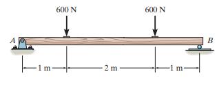
Draw the shear and moment diagrams for the beam. 600 N 600 N B 2 m m- m
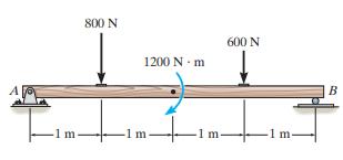
Draw the shear and moment diagrams for the beam. 800 N 600 N 1200 N m B 1m -1 m- 1 m- m
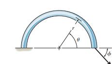
Determine the internal normal force, shear force, and moment in the curved rod as a function of θ. The force P acts at the constant angle ϕ.
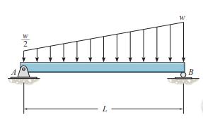
Draw the shear and moment diagrams for the beam. B
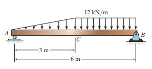
Draw the shear and moment diagrams for the beam. 12 kN/m A B IC 3 m 6 m
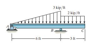
Draw the shear and moment diagrams for the beam 3 kip/ft 2 kip/ft B 6 ft 3 ft
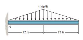
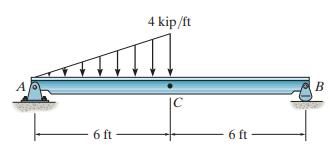
Draw the shear and moment diagrams for the beam. 4 kip/ft A 12 ft 12 ft
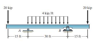
Draw the shear and moment diagrams for the beam. 20 kip 20 kip 4 kip/ft 111111111|| B -15 ft- 30 ft 15 ft
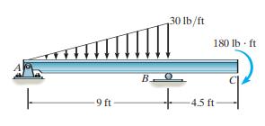
Draw the shear and moment diagrams for the beam. 130 lb/ft 180 Ib ft В. -9 ft- 4.5 ft
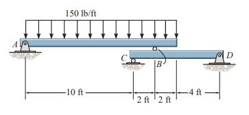
Draw the shear and bending-moment diagrams for each of the two segments of the compound beam. 150 lb/ft D B -10 ft -4 ft 2 ft '2 ft
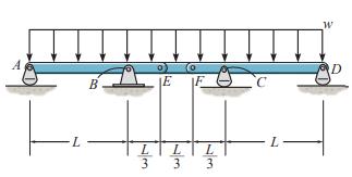
Draw the shear and moment diagrams for the compound beam. The beam is pin-connected at E and F. D B -JE E 3 3 3
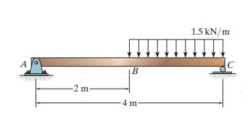
Draw the shear and moment diagrams for the beam. 1.5 kN/m A B -2 m- 4 m
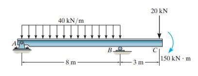
Draw the shear and moment diagrams for the beam. 20 kN 40 kN/m B- 150 kN · m 8 m 3 m
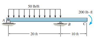
Draw the shear and bending-moment diagrams for the beam. 50 Ib/ft 200 lb-ft A B 20 ft 10 ft
Draw the shear and moment diagrams for the beam. B
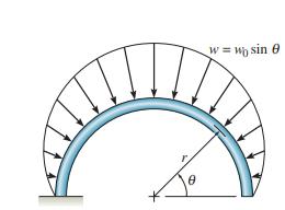
Solve Prob. 7–39 for u = 120°. Data From Problem 7he distributed loading sin ω = ω sinθ, measured per unit length, acts on the curved rod. Determine the internal normal force,shear force, and moment in the rod at θ = 45°. W = W) sin e
he distributed loading sin ω = ω sinθ, measured per unit length, acts on the curved rod. Determine the internal normal force,shear force, and moment in the rod at θ = 45°. W = W) sin e
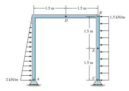
Determine the internal normal force, shear force, and moment at point E. 1.5 m 1.5 m B 1.5 kN/m 1.5 m E 1.5 m 2 kN/m A C
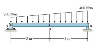
Determine the internal normal force, shear force, and moment at point C of the beam. 400 N/m 200 N/m C 3m 3 m
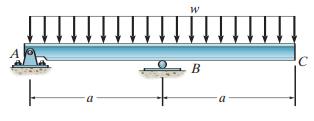
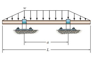
Determine the distance a between the bearings in terms of the shaft’s length L so that the moment in the symmetric shaft is zero at its center. a L
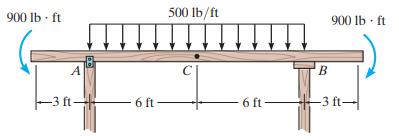
Determine the internal shear force and moment acting at point C in the beam. Support Reactions. Referring to the FBD of the entire beam shown in Fig. a 900 lb ft 500 lb/ft 900 lb · ft A -3 ft- 6 ft- 6 ft- –3 ft-
Determine the internal shear force and moment acting at point C in the beam. 4 kip/ft A 6 ft 6 ft
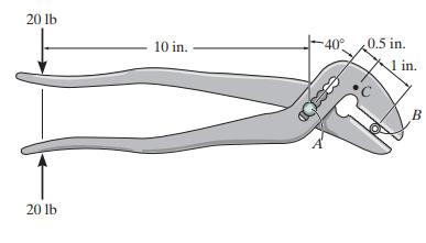
The pliers are used to grip the tube at B. If a force of 20 lb is applied to the handles,determine the internal shear force and moment at point C. Assume the jaws of the pliers exert only normal forces on the tube. 20 lb 10 in. 40° 0.5 in. 1 in. B 20 lb
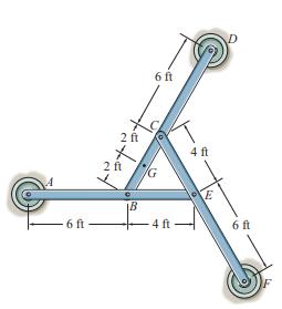
The three pin-connected members shown in the top view support a downward force of 60 lb at G.If only vertical forces are supported at the connections B, C, E and pad supports A, D, F, determine the reactions at each pad. 6 ft 2 ft 4 ft 2 ft 6 ft 4 ft 6 ft
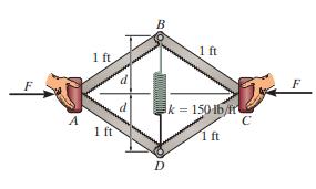
If a force of F = 50 Ib is applied to the pads at A and C, determine the smallest dimension d required for equilibrium if the spring has an unstretched length of 1 ft. B 1 ft 1 ft F k = 15016/fr 1ft 1 ft D
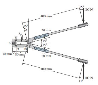
Determine the force that the jaws J of the metal cutters exert on the smooth cable C if 100-N forces are applied to the handles. The jaws are pinned at E and A, and D and B. There is also a pin at F. 100 N 400 mm 20 mm /15° 30 mm šo mm/ 20 mm 400 mm 100 N 15°
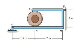
Determine the force that the smooth 20-kg cylinder exerts on members AB and CDB. Also, what are the horizontal and vertical components of reaction at pin A? D. 1 m B 1.5 m 2 m
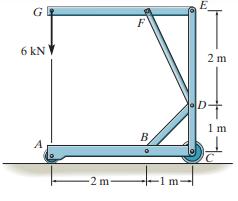
Determine the force in members FD and DB of the frame. Also, find the horizontal and vertical components of reaction the pin at C exerts on member ABC and member EDC. E G F 6 kN 2 m 1 m B -2 m- -1 m
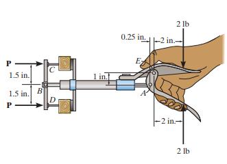
When a force of 2 lb is applied to the handles of the brad squeezer, it pulls in the smooth rod AB. Determine the force P exerted on each of the smooth brads at C and D. 2 lb 0.25 in.-2 in. Ez 1.5 in. 1 1.5 in. B P -2 in- 2 lb
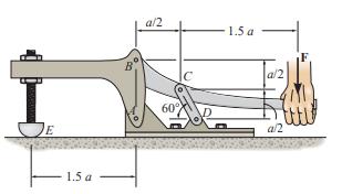
The toggle clamp is subjected to a force F at the handle. Determine the vertical clamping force acting at E.
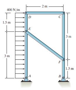
Determine the horizontal and vertical components of force which the pins at A and B exert on the frame. 2 m 400 N/m 1.5 m E 3 m 3 m F 1.5 m B
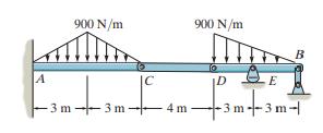
Determine the reactions at the supports at A, E, and B of the compound beam. 900 N/m 900 N/m B A |C. D E 3 m- -3 m--3 m- 3 m- 4 m
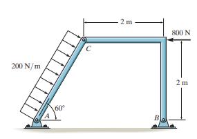
Determine the resultant force at pins A, B, and C on the three-member frame. 2 m 800 N 200 N/m 2 m 60 B
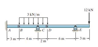
Determine the reactions at the supports A, C, and E of the compound beam. 12 kN 3 kN/m A |B C |D E F3 m- 4 m 6 m 3 m 2 m
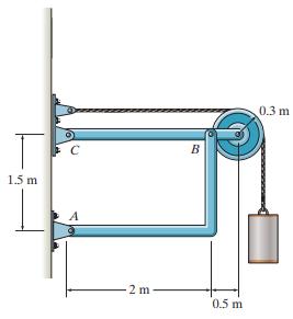
Determine the horizontal and vertical components of force at pins B and C. The suspended cylinder has a mass of 75 kg. 0.3 m B 1.5 m A 2 m 0.5 m
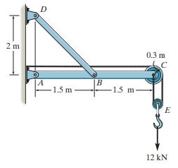
Determine the horizontal and vertical components of force at pins A and D. D 2 m 0.3 m 14 1.5 m -1.5 m E 12 kN
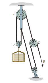
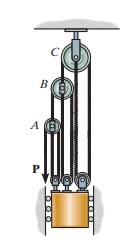
Determine the force P required to hold the 150-kg crate in equilibrium. B P
Determine the force P required to hold the 50-kg mass in equilibrium. B
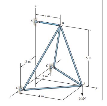
Determine the force in each member of the space truss and state if the members are in tension or compression. The support reaction at E acts along member EB. Why? 2 m. E Co B 5 m 3 m 3 m 4 m 6 KN
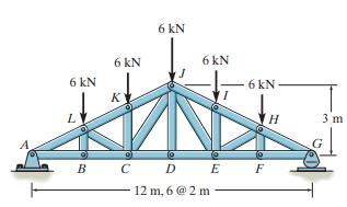
Determine the force in members CD, CJ, and KJ and state if these members are in tension or compression. 6 kN 6 kN 6 kN 6 kN 6 kN K 3 m B C DE F В 12 m, 6 @ 2 m
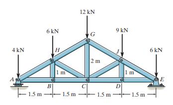
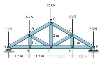
Determine the force in members CD, CJ, GJ, and CG and state if these members are in tension or compression. 12 kN 6 kN 9 kN 4 kN H 6 kN 2 m 1 m 1 m A E B| - 1.5 m D 1.5 m 1.5 m 1.5 m
Determine the force in members BC, HC, and HG. State if these members are in tension or compression. 12 kN 6 kN 9 kN G 4 kN 6 kN 2 m 1 m 1 m A E B D 1.5 m 1.5 m 1.5 m 1.5 m
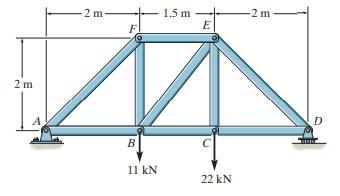
Determine the force developed in members FE, EB, and BC of the truss and state if these members are in tension or compression. 1.5 m E 2 m -2 m F 2 m B 11 kN 22 kN
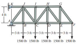
Determine the force in members CD, HI, and CJ of the truss, and state if the members are in tension or compression. H G 4 ft B [C ID E -3 ft--3 ft--3 ft--3 ft-|-3 ft- 1500 Ib 1500 lb 1500 lb 1500 Ib 1500 lb
Determine the force in members HG, HE, and DE of the truss, and state if the members are in tension or compression. H G 4 ft B [C ID E -3 ft--3 ft--3 ft--3 ft-|-3 ft- 1500 Ib 1500 lb 1500 lb 1500 Ib 1500 lb
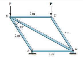
The maximum allowable tensile force in the members of the truss is (Ft)max = 5 kN, and the maximum allowable compressive force is (Fc)max = 3 kN. Determine the maximum magnitude P of the two loads that can be applied to the truss. P P 2 m D 30 2 m 2 m B 2 m
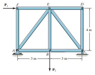
Determine the force in each member of the truss and state if the members are in tension or compression. Set P1 = 30 kN, P2 = 15 kN. D E P 4 m B 3 m 3 m P2
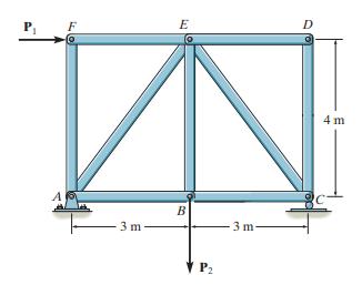
Determine the force in each member of the truss and state if the members are in tension or compression. Set P1 = 9 kN, P2 = 15 kN. D E 4 m A В 3 m 3 m- V P2
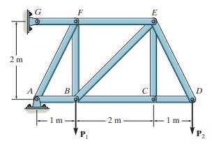
Determine the force in each member of the truss and state if the members are in tension or compression. Set P1 = 8 kN, P2 = 12 kN. F E 2 m D. A B 2 m P2
Determine the force in each member of the truss and state if the members are in tension or compression. Set P1 = 10 kN, P2 = 8 kN. F E 2 m D. A B 2 m P2
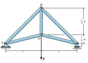
Members AB and BC can each support a maximum compressive force of 800 lb, and members AD, DC, and BD can support a maximum tensile force of 2000 lb. If a = 6 ft, determine the greatest load P the truss can support. B A,
Members AB and BC can each support a maximum compressive force of 800 lb, and members AD, DC, and BD can support a maximum tensile force of 1500 lb. If a = 10ft, determine the greatest load P the truss can support. B A,
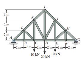
Determine the force in each member of the Pratt truss, and state if the members are in tension or compression. 2 m K. 2 m 2 m AG C E -2 m--2 m--2 m--2 m--2 m--2 m- |B 10 kN 10 kN 20 kN
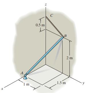
The smooth uniform rod AB is supported by a ball-and-socket joint at A, the wall at B, and cable BC. Determine the components of reaction at A, the tension in the cable, and the normal reaction at B if the rod has a mass of 20 kg. 0.5 m 2 m 1.5 m 1 m
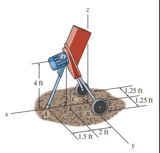
The 50-lb mulching machine has a center of gravity at G. Determine the vertical reactions at the wheels C and B and the smooth contact point A. 4 ft 25 ft 1.25 ft 2 ft 1.5 ft y
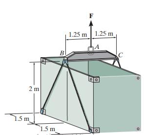
The uniform load has a mass of 600 kg and is lifted using a uniform 30-kg strongback beam BAC and four wire ropes as shown. Determine the tension in each segment of rope and the force that must be applied to the sling at A. 1.25 m 1.25 m B 2 m .5 m 1.5 m
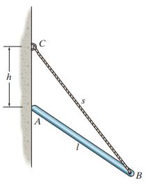
The 30-N uniform rod has a length of l = 1m. If , determine the distance h of placement at the end A along the smooth wall for equilibrium. h B
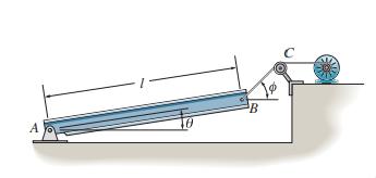
The uniform beam has a weight W and length l and is supported by a pin at A and a cable BC. Determine the horizontal and vertical components of reaction at A and the tension in the cable necessary to hold the beam in the position shown. B A
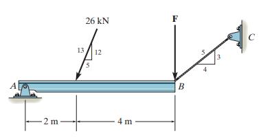
If rope BC will fail when the tension becomes 50 kN, determine the greatest vertical load F that can be applied to the beam at B. What is the magnitude of the reaction at A for this loading? Neglect the thickness of the beam. F 26 kN 13 12 B 4 m 2 m
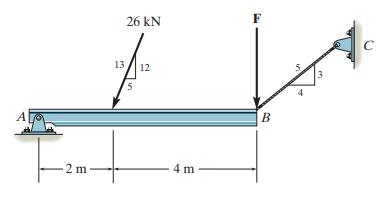
Determine the reactions at the pin A and the tension in cord BC. Set F = 40 kN. Neglect the thickness of the beam. 26 kN C 13 12 A В 2 m 4 m
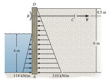
The bulk head AD is subjected to both water and soilbackfill pressures. Assuming AD is “pinned” to the ground at A, determine the horizontal and vertical reactions there and also the required tension in the ground anchor BC necessary for equilibrium. The bulk head has a mass of 800 kg. 0.5 m B
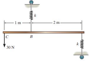
Determine the stiffness k of each spring so that the 30-N force causes the bar to tip θ = 15° when the force is applied. Originally the bar is horizontal and the springs are unstretched. Neglect the weight of the bar. 1 m 2 m B k 30 N www
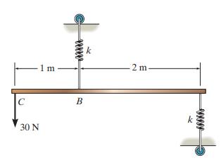
The bar of negligible weight is supported by two springs, each having a stiffness k = 100 N>m. If the springs are originally unstretched, and the force is vertical as shown, determine the angle u the bar makes with the horizontal, when the 30-N force is applied to the bar. 2 m m B 30 N ww
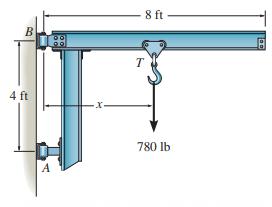
The cantilevered jib crane is used to support the load of 780 lb. If x = 5 ft, determine the reactions at the supports. Note that the supports are collars that allow the crane to rotate freely about the vertical axis.The collar at B supports a force in the vertical direction, whereas the one at A
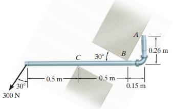
The smooth pipe rests against the opening at the points of contact A, B, and C. Determine the reactions at these points needed to support the force of 300 N. Neglect the pipe’s thickness in the calculation. A 0.26 m 30° { 0.5 m 0.5 m 30° 0.15 m 300 N
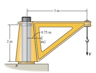
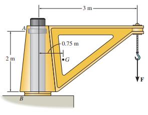
The dimensions of a jib crane, which is manufactured by the Basick Co., are given in the figure. The crane has a mass of 800 kg and a center of mass at G.The bearing at A is a journal bearing and can support a horizontal force, whereas the bearing at B is a thrust bearing that supports both
The dimensions of a jib crane, which is manufactured by the Basick Co., are given in the figure. If the crane has a mass of 800 kg and a center of mass at G, and the maximum rated force at its end is F = 15 kN, determine the reactions at its bearings. The bearing at A is a journal bearing and
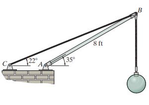
Determine the magnitude of force at the pin A and in the cable BC needed to support the 500-lb load. Neglect the weight of the boom AB. 8 ft 122° 35
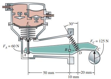
The operation of the fuel pump for an automobile depends on the reciprocating action of the rocker arm ABC, which is pinned at B and is spring loaded at A and D. When the smooth cam C is in the position shown, determine the horizontal and vertical components of force at the pin and the force along
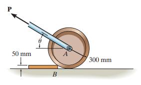
Determine the magnitude and direction u of the minimum force P needed to pull the 50-kg roller over the smooth step 50 mm 300 mm
Determine the force P needed to pull the 50-kg roller over the smooth step. Take u = 30°. 50 mm 300 mm
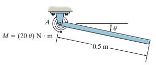
A linear torsional spring deforms such that an applied couple moment M is related to the spring’s rotation u in radians by the equation M = (20 u) N # m. If such a spring is attached to the end of a pin-connected uniform 10-kg rod, determine the angle u for equilibrium. The spring is undeformed
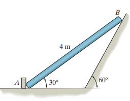
Determine the reactions acting on the smooth uniform bar, which has a mass of 20 kg. B 4 m AK 60° 30°
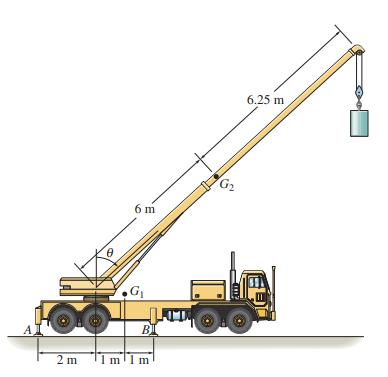
The mobile crane is symmetrically supported by two outriggers at A and two at B in order to relieve the suspension of the truck upon which it rests and to provide greater stability. If the crane and truck have a mass of 18 Mg and center of mass at G1, and the boom has a mass of 1.8 Mg and a center
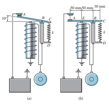
The relay regulates voltage and current. Determine the force in the spring CD, which has a stiffness of k 120 N m, so that it will allow the armature to make contact atA in figure (a) with a vertical force of 0.4 N. Also, determine the force in the spring when the coil is energized and attracts the
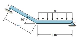
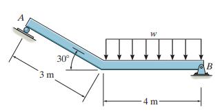
If the roller at A and the pin at B can support a load up to 4 kN and 8 kN, respectively, determine the maximum intensity of the distributed load w, measured in kN/m, so that failure of the supports does not occur. 30° 3 m 4 m
If the intensity of the distributed load acting on the beam is w = 3 kN/m, determine the reactions at the roller A and pin B. А 30° B 3 m 4 m
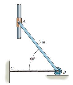
The uniform rod AB has a mass of 40 kg. Determine the force in the cable when the rod is in the position shown. There is a smooth collar at A. 3 m 60° C B
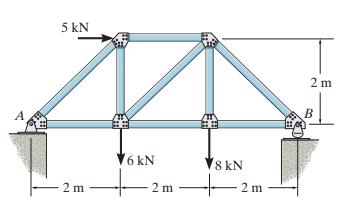
Determine the reactions at the supports. 5 kN 2 m A B V6 kN 8 kN 2 m 2 m 2 m
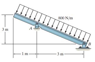
Determine the reactions at the supports. 800 N/m A 3 m 1 m -3 m-
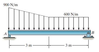
Determine the reactions at the supports. 900 N/m 600 N/m A 3 m 3 m
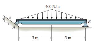
Determine the reactions at the supports. 400 N/m B 3 m -3 m in
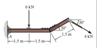
Determine the components of the support reactions at the fixed support A on the cantilevered beam. 6 kN 30 130° 1.5 m tiso 4 kN -1.5 m- 1.5 m-
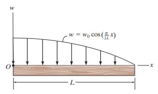
Replace the loading by an equivalent resultant force and couple moment acting at point O. w = wo cos (x)
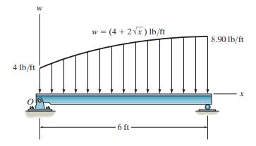
Determine the magnitude of the equivalent resultant force and its location, measured from point O. w = (4 + 2V) Ib/ft | 8.90 lb/ft 4 lb/ft -6 ft-
Determine the length b of the triangular load and its position a on the beam such that the equivalent resultant force is zero and the resultant couple moment is 8 kN•m clockwise. 6 kN/m 2 kN/m 4 m
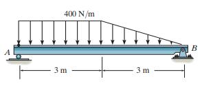
Replace the loading by a single resultant force, and specify its location on the beam measured from point A. 400 N/m B 3 m 3 m
Replace the loading by an equivalent resultant force and couple moment acting at point A. 400 N/m B 3 m 3 m
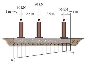
If the soil exerts a trapezoidal distribution of load on the bottom of the footing, determine the intensities w1 and w2 of this distribution needed to support the column loadings. 80 kN 60 kN 50 kN 1 m -2.5 m- -3.5 m 1 m W2 W1
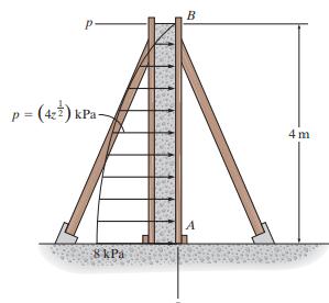
The form is used to cast a concrete wall having a width of 5 m. Determine the equivalent resultant force the wet concrete exerts on the form AB if the pressure distribution due to the concrete can be approximated as shown. Specify the location of the resultant force, measured from point B. B
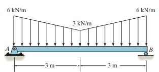
Replace the distributed loading by an equivalent resultant force and couple moment acting at point A. 6 kN/m 6 kN/m 3 kN/m B -3 m 3 m
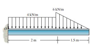
Replace this loading by an equivalent resultant force and specify its location, measured from point O. 6 kN/m 4 kN/m 2 m 15 m.
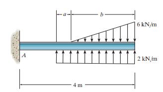
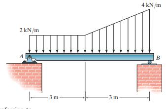
Replace the distributed loading by an equivalent resultant force, and specify its location on the beam, measured from the pin at A. 4 kN/m 2 kN/m -3 m -3 m
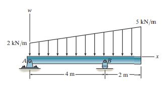
Replace the loading by an equivalent resultant force and specify its location on the beam, measured from point A. 5 kN/m 2 kN/m 4 m- 2 m
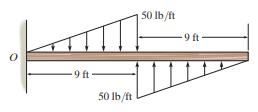
Replace the loading by an equivalent resultant force and couple moment acting at point O. 50 Ib/ft -9 ft 9 ft 50 Ib/ft
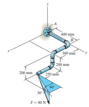
Replace the force of F = 80 N acting on the pipe assembly by an equivalent resultant force and couple moment at point A. A 400 mm B 300 mm 200 mm 200 mm 250 mm 40 30° F = 80 N
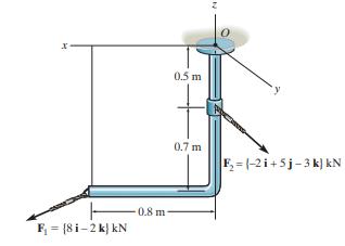
Replace the loading by an equivalent resultant force and couple moment at point O. 0.5 m y 0.7 m F =(-2i+5j-3 k) kN 0.8 m- F = [8 i-2 k} kN
The forces F1 = {-4i + 2j - 3k} kN and F2 = {3i - 4j - 2k} kN act on the end of the beam. Replace these forces by an equivalent force and couple moment acting at point O.
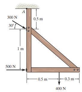
Replace the force system acting on the frame by an equivalent resultant force and couple moment acting at point A. A 300 N 0.5 m 30°/ 1 m 500 N 0.5 m 0.3 m - - 400 N
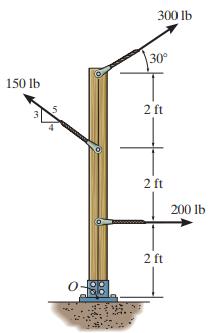
Replace the force system acting on the post by a resultant force and couple moment at point O. 300 lb 30° 150 lb 2 ft 2 ft 200 lb 2 ft in
Showing 2200 - 2300
of 2426
First
11
12
13
14
15
16
17
18
19
20
21
22
23
24
25
Step by Step Answers