New Semester
Started
Get
50% OFF
Study Help!
--h --m --s
Claim Now
Question Answers
Textbooks
Find textbooks, questions and answers
Oops, something went wrong!
Change your search query and then try again
S
Books
FREE
Study Help
Expert Questions
Accounting
General Management
Mathematics
Finance
Organizational Behaviour
Law
Physics
Operating System
Management Leadership
Sociology
Programming
Marketing
Database
Computer Network
Economics
Textbooks Solutions
Accounting
Managerial Accounting
Management Leadership
Cost Accounting
Statistics
Business Law
Corporate Finance
Finance
Economics
Auditing
Tutors
Online Tutors
Find a Tutor
Hire a Tutor
Become a Tutor
AI Tutor
AI Study Planner
NEW
Sell Books
Search
Search
Sign In
Register
study help
engineering
introduction to fluid mechanics
Fox And McDonald's Introduction To Fluid Mechanics 9th Edition Philip J. Pritchard, John W. Mitchell - Solutions
A fire nozzle is supplied through \(300 \mathrm{ft}\) of 3-in.-diameter canvas hose with \(e=0.001 \mathrm{ft}\). Water from a hydrant is supplied at \(50 \mathrm{psig}\) to a booster pump on board the pumper truck. At design operating conditions, the pressure at the nozzle inlet is \(100
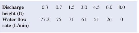
Manufacturer's data for a submersible utility pump areThe owner's manual also states, These ratings are based on discharge into 25 -mm-diameter pipe with friction loss neglected. Using 20-mm-diameter garden hose adaptor, performance will be reduced approximately 15 percent." Plot a performance
Water is pumped from a lake at \(z=0\) to a large storage tank located on a bluff above the lake. The pipe is 3-in.-diameter galvanized iron. The inlet section between the lake and the pump includes one rounded inlet, one standard \(90^{\circ}\) elbow, and \(50 \mathrm{ft}\) of pipe. The discharge
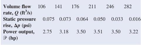
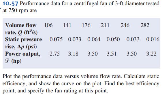
Performance data for a centrifugal fan of 3-ft diameter tested at \(750 \mathrm{rpm}\) arePlot the performance data versus volume flow rate. Calculate static efficiency, and show the curve on the plot. Find the best efficiency point, and specify the fan rating at this point. Volume flow 106 141 176
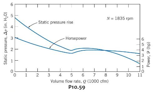
The performance data of Problem 10.57 are for a 36-in.diameter fan wheel. The fan also is manufactured with 42-, 48-, 54-, and 60-in.-diameter wheels. Pick a standard fan to deliver \(600 \mathrm{ft}^{3} / \mathrm{s}\) against a 1-in. water static pressure rise. Determine the required fan speed and
Performance characteristics of a Howden Buffalo axial flow fan are presented below. The fan is used to power a wind tunnel with \(1-\mathrm{ft}\)-square test section. The tunnel consists of a smooth inlet contraction, two screens each with loss coefficient \(K=0.12\), the test section, and a
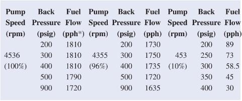
Experimental test data for an aircraft engine fuel pump are presented below. This gear pump is required to supply jet fuel at 450 pounds per hour and \(150 \mathrm{psig}\) to the engine fuel controller. Tests were conducted at 10,96, and 100 percent of the rated pump speed of \(4536 \mathrm{rpm}\).
Preliminary calculations for a hydroelectric power generation site show a net head of \(2350 \mathrm{ft}\) is available at a water flow rate of \(75 \mathrm{ft}^{3} / \mathrm{s}\). Compare the geometry and efficiency of Pelton wheels designed to run at(a) \(450 \mathrm{rpm}\) (b) \(600
Conditions at the inlet to the nozzle of a Pelton wheel are \(p=700 \mathrm{psig}\) and \(V=15 \mathrm{mph}\). The jet diameter is \(d=7.5 \mathrm{in}\). and the nozzle loss coefficient is \(K_{\text {nozle }}=0.04\). The wheel diameter is \(D=8 \mathrm{ft}\). At this operating condition,
A Francis turbine is to operate under a head of \(46 \mathrm{~m}\) and deliver 18.6 MW while running at \(150 \mathrm{rpm}\). The runner diameter is \(4 \mathrm{~m}\). A 1-m-diameter model is operated in a laboratory under the same head. Find the model speed, power, and flow rate.
A Kaplan (propeller with variable-pitch blades) turbine with a rated capacity of \(83 \mathrm{MW}\) at a head of \(24 \mathrm{~m}\) and \(86 \mathrm{rpm}\) was one of 14 units installed at the McNary project on the Columbia River. The characteristic runner diameter is \(7 \mathrm{~m}\). If a
Francis turbine Units 19, 20, and 21, installed at the Grand Coulee Dam on the Columbia River, are very large [55]. Each runner is \(32.6 \mathrm{ft}\) in diameter and contains 550 tons of cast steel. At rated conditions, each turbine develops \(820,000 \mathrm{hp}\) at \(72 \mathrm{rpm}\) under
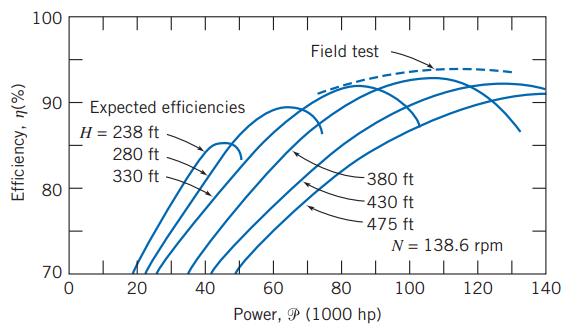
Measured data for performance of the reaction turbines at Shasta Dam near Redding, California, are shown in Fig. 10.38. Each turbine is rated at \(103,000 \mathrm{hp}\) when operating at \(138.6 \mathrm{rpm}\) under a net head of \(380 \mathrm{ft}\). Evaluate the specific speed and compute the
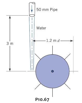
For a flow rate of \(12 \mathrm{~L} / \mathrm{s}\) and turbine speed of \(65 \mathrm{rpm}\), estimate the power transferred from jet to turbine wheel. 3 m 50 mm Pipe Water -1.2 md- P10.67
The velocity of the water jet driving this impulse turbine is \(45 \mathrm{~m} / \mathrm{s}\). The jet has a \(75-\mathrm{mm}\) diameter. After leaving the buckets the absolute velocity of the water is observed to be \(15 \mathrm{~m} / \mathrm{s}\) in a direction \(60^{\circ}\) to that of the
An impulse turbine is to develop \(15 \mathrm{MW}\) from a single wheel at a location where the net head is \(350 \mathrm{~m}\). Determine the appropriate speed, wheel diameter, and jet diameter for single- and multiple-jet operation. Compare with a double-overhung wheel installation. Estimate the
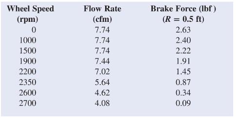
An impulse turbine under a net head of \(33 \mathrm{ft}\) was tested at a variety of speeds. The flow rate and the brake force needed to set the impeller speed were recorded:Calculate and plot the machine power output and efficiency as a function of water turbine speed. Wheel Speed (rpm) Flow Rate
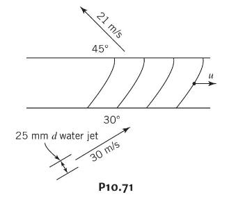
The absolute velocities and directions of the jets entering and leaving the blade system are as shown. Calculate the power transferred from the jet to the blade system and the blade angles required. 21 m/s 45 25 mm d water jet 30 30 m/s P10.71
A small hydraulic impulse turbine is supplied with water through a penstock with diameter \(D\) and length \(L\); the jet diameter is \(d\). The elevation difference between the reservoir surface and nozzle centerline is \(Z\). The nozzle head loss coefficient is \(K_{\text {nozzle }}\) and the
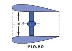
A fanboat in the Florida Everglades is powered by a propeller with \(D=1.5 \mathrm{~m}\) driven at maximum speed, \(N=1800 \mathrm{rpm}\), by a \(125 \mathrm{~kW}\) engine. Estimate the maximum thrust produced by the propeller at(a) standstill (b) \(V=12.5 \mathrm{~m} / \mathrm{s}\).
A jet-propelled aircraft traveling at \(225 \mathrm{~m} / \mathrm{s}\) takes in \(50 \mathrm{~kg} / \mathrm{s}\) of air. If the propulsive efficiency (defined as the ratio of the useful work output to the mechanical energy input to the fluid) of the aircraft is 45 percent, determine the speed at
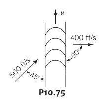
When an air jet of 1-in.-diameter strikes a series of blades on a turbine rotor, the absolute velocities are as shown. If the air is assumed to have a constant specific weight of \(0.08 \mathrm{lb} / \mathrm{ft}^{3}\), what is the force on the turbine rotor? How much horsepower is transferred to
The volume flow rate through the propeller of an airboat (a boat driven by a propeller moving air) is \(50 \mathrm{~m}^{3} / \mathrm{s}\). When the boat is docked, the speed of the slipstream behind the propeller at a location where the flow has returned atmospheric pressure is \(40 \mathrm{~m} /
The propeller for the Gossamer Condor human-powered aircraft has \(D=12 \mathrm{ft}\) and rotates at \(N=107 \mathrm{rpm}\). The wing loading is \(0.4 \mathrm{lbf} / \mathrm{ft}^{2}\) of wing area, the drag is approximately \(6 \mathrm{lbf}\) at \(12 \mathrm{mph}\), the total weight is \(200
A typical American multiblade farm windmill has \(D=7 \mathrm{ft}\) and is designed to produce maximum power in winds with \(V=15 \mathrm{mph}\). Estimate the rate of water delivery as a function of the height to which the water is pumped.
An airplane flies at \(200 \mathrm{~km} / \mathrm{h}\) through still air of specific weight \(12 \mathrm{~N} / \mathrm{m}^{3}\). The propeller is \(2.4 \mathrm{~m}\) in diameter and its slipstream has a velocity of \(290 \mathrm{~km} / \mathrm{h}\) relative to the fuselage. Calculate(a) the
This ducted propeller unit drives a ship through still water at a speed of \(4.5 \mathrm{~m} / \mathrm{s}\). Within the duct the mean velocity of the water relative to the unit is \(15 \mathrm{~m} / \mathrm{s}\). Calculate the propulsive force produced by the unit. Calculate the force exerted on
A model of an American multiblade farm windmill is to be built for display. The model, with \(D=1 \mathrm{~m}\), is to develop full power at \(V=10 \mathrm{~m} / \mathrm{s}\) wind speed. Calculate the angular speed of the model for optimum power generation. Estimate the power output.
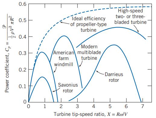
A large Darrieus vertical axis wind turbine was built by the U.S. Department of Energy near Sandia, New Mexico [48]. This machine is \(18 \mathrm{~m}\) tall and has a \(5-\mathrm{m}\) radius; the area swept by the rotor is over \(110 \mathrm{~m}^{2}\). If the rotor is constrained to rotate at \(70
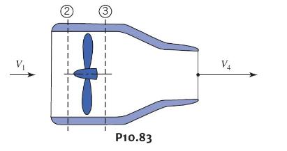
Show that this ducted propeller system when moving forward at velocity \(V_{1}\) will have an efficiency given by \(2 V_{1} /\left(V_{4}+V_{1}\right)\). If for a specific design and point of operation, \(V_{2} / V_{1}=9 / 4\) and \(V_{4} / V_{2}=5 / 4\), what fraction of the propulsive force will
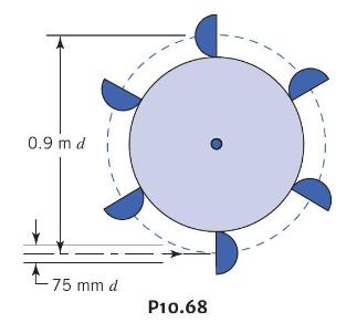
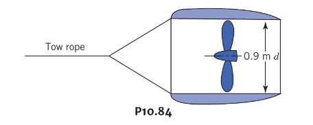
This ducted propeller unit (now operating as a turbine) is towed through still water at a speed of \(7.5 \mathrm{~m} / \mathrm{s}\). Calculate the maximum power that the propeller can develop. Neglect all friction effects. Tow rope P10.84 -0.9 m d
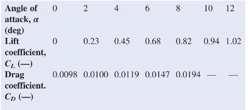
Aluminum extrusions, patterned after NACA symmetric airfoil sections, frequently are used to form Darrieus wind turbine "blades." Below are section lift and drag coefficient data [57] for a NACA 0012 section tested at \(R e=6 \times 10^{6}\) with standard roughness. The section stalled for
What is the maximum power that can be expected from a windmill \(30 \mathrm{~m}\) in diameter in a wind of \(50 \mathrm{~km} / \mathrm{h}\) ? Assume air density \(1.225 \mathrm{~kg} / \mathrm{m}^{3}\).
If an ideal windmill is operating at best efficiency in a wind of \(48 \mathrm{~km} / \mathrm{h}\), what is the velocity through the disk and at some distance behind the windmill? What is the thrust on this windmill, assuming a diameter of \(60 \mathrm{~m}\) and an air density of \(1.23
A prototype air compressor with a compression ratio of 7 is designed to take \(8.9 \mathrm{~kg} / \mathrm{s}\) air at 1 atmosphere and \(20^{\circ} \mathrm{C}\). The design point speed, power requirement, and efficiency are \(600 \mathrm{rpm}\), 5.6 MW, and 80 percent, respectively. A 1:5-scale
A compressor has been designed for entrance conditions of \(14.7 \mathrm{psia}\) and \(70^{\circ} \mathrm{F}\). To economize on the power required, it is being tested with a throttle in the entry duct to reduce the entry pressure. The characteristic curve for its normal design speed of \(3200
We have seen many examples in Chapter 7 of replacing working fluids in order to more easily achieve similitude between models and prototypes. Describe the effects of testing an air compressor using helium as the working fluid on the dimensionless and dimensional parameters we have discussed for
The roof of a minivan is approximated as a horizontal flat plate. Plot the length of the laminar boundary layer as a function of minivan speed, \(V\), as the minivan accelerates from \(10 \mathrm{mph}\) to \(90 \mathrm{mph}\).
A model of a river towboat is to be tested at \(1: 18\) scale. The boat is designed to travel at \(3.5 \mathrm{~m} / \mathrm{s}\) in fresh water at \(10^{\circ} \mathrm{C}\). Estimate the distance from the bow where transition occurs. Where should transition be stimulated on the model towboat?
For flow over a smooth plate, what approximately is the maximum length of the laminar boundary layer if \(V_{o}=9.0 \mathrm{~m} / \mathrm{s}\) in the irrotational uniform flow and the fluid is air? Water?
A model of a thin streamlined body is placed in a flow for testing. The body is \(0.9 \mathrm{~m}\) long and the flow velocity is \(0.6 \mathrm{~m} / \mathrm{s}\). What \(u\) is needed to ensure that the boundary layer on the body is laminar?
A student is to design an experiment involving dragging a sphere through a tank of fluid to illustrate(a) "creeping flow" \(\left(R e_{D}
A \(1 \mathrm{~m} \times 2 \mathrm{~m}\) sheet of plywood is attached to the roof of your vehicle after being purchased at the hardware store. At what speed (in kilometers per hour) in \(20^{\circ} \mathrm{C}\) air will the boundary layer first start becoming turbulent? At what speed is about 90
The extent of the laminar boundary layer on the surface of an aircraft or missile varies with altitude. For a given speed, will the laminar boundary-layer length increase or decrease with altitude? Why? Plot the ratio of laminar boundary-layer length at altitude \(z\), to boundary-layer length at
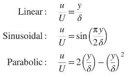
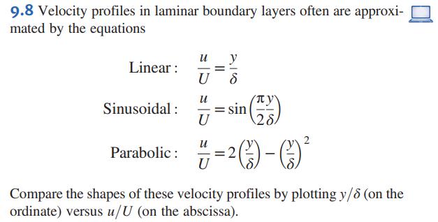
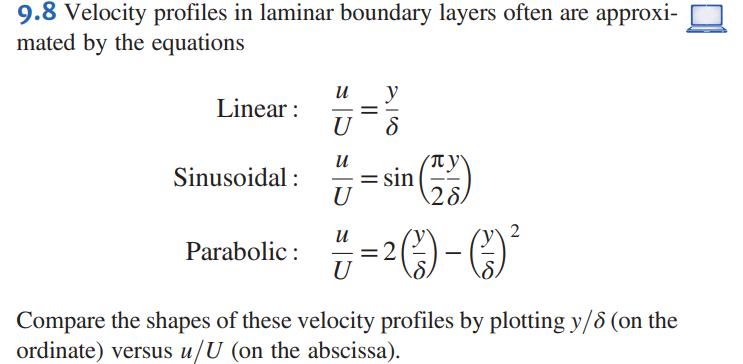
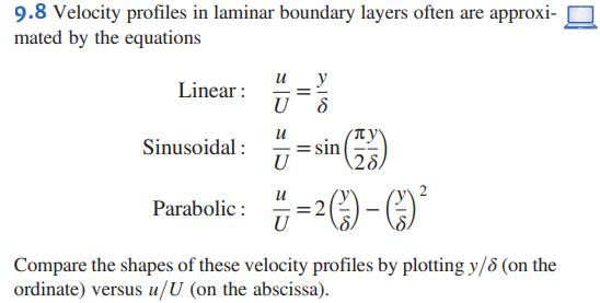
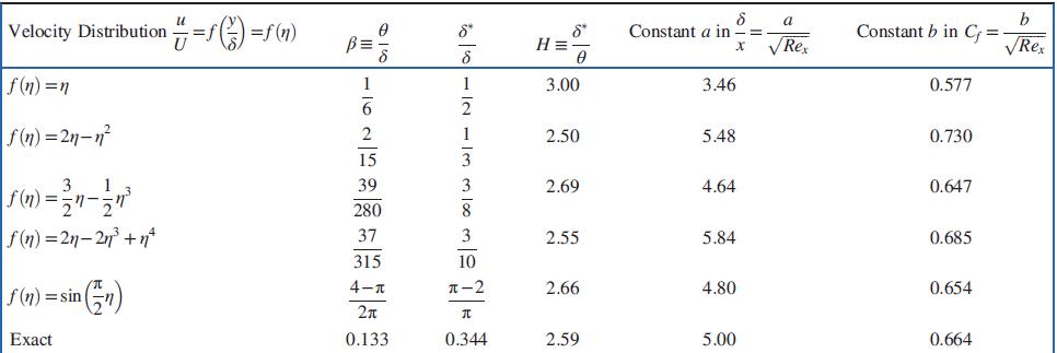
Velocity profiles in laminar boundary layers often are approximated by the equationsCompare the shapes of these velocity profiles by plotting \(y / \delta\) (on the ordinate) versus \(u / U\) (on the abscissa). Linear: u U u y = sin (128) Sinusoidal: "=sin(**) U u Parabolic: =2)-( U
An approximation for the velocity profile in a laminar boundary layer isDoes this expression satisfy boundary conditions applicable to the laminar boundary-layer velocity profile? Evaluate \(\delta^{*} / \delta\) and \(\theta / \delta\). n 4 + U
Evaluate \(\theta / \delta\) for each of the laminar boundary-layer velocity profiles given in Problem 9.8.Data From Problem 9.8 9.8 Velocity profiles in laminar boundary layers often are approxi- mated by the equations Linear: 97 U u Sinusoidal: = sin U 28 u Parabolic: -2- U Compare the shapes of
Evaluate the displacement thickness \(\delta^{*}\) and the momentum thickness \(\theta\) for a velocity profile given by \(\frac{u}{U}=\frac{y}{\delta}\). Plot the nondimensional velocity profile and show the thicknesses \(\frac{\delta^{*}}{y}\) and \(\frac{\theta}{y}\) on the plot. Does this
Evaluate the displacement thickness \(\delta^{*}\) and the momentum thickness \(\theta\) for a power law velocity profile given by \(\frac{u}{U}=\left(\frac{y}{\delta}\right)^{1 / 7}\). Plot the nondimensional velocity profile and show the thicknesses \(\frac{\delta^{*}}{y}\) and
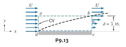
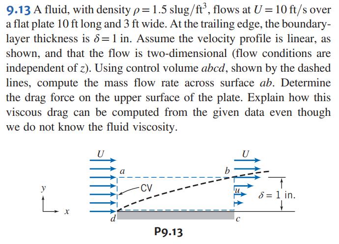
A fluid, with density \(ho=1.5 \mathrm{slug} / \mathrm{ft}^{3}\), flows at \(U=10 \mathrm{ft} / \mathrm{s}\) over a flat plate \(10 \mathrm{ft}\) long and \(3 \mathrm{ft}\) wide. At the trailing edge, the boundarylayer thickness is \(\delta=1 \mathrm{in}\). Assume the velocity profile is linear, as
Solve Problem 9.13 with the velocity profile at section \(b c\) given by the parabolic expression from Problem 9.8.Data From Problem 9.13Data From Problem 9.8 9.13 A fluid, with density p = 1.5 slug/ft, flows at U = 10 ft/s over a flat plate 10 ft long and 3 ft wide. At the trailing edge, the
Air flows in a horizontal cylindrical duct of diameter \(D=100 \mathrm{~mm}\). At a section a few meters from the entrance, the turbulent boundary layer is of thickness \(\delta_{1}=5.25 \mathrm{~mm}\), and the velocity in the inviscid central core is \(U_{1}=12.5 \mathrm{~m} / \mathrm{s}\).
Evaluate the displacement thickness \(\delta^{*}\) and the momentum thickness \(\theta\) for the profile given by \(\frac{u}{U}=2\left(\frac{y}{\delta}\right)-\left(\frac{y}{\delta}\right)^{2}\). Plot the nondimensional velocity profile and show the thicknesses \(\frac{\delta^{*}}{y}\) and
Evaluate the displacement thickness \(\delta^{*}\) and the momentum thickness \(\theta\) for a velocity profile given by \(\frac{u}{U}=\sin \left(\frac{\pi y}{2 \delta}\right)\). Plot the nondimensional velocity profile and show the thicknesses \(\frac{\delta^{*}}{y}\) and \(\frac{\theta}{y}\) on
A laboratory wind tunnel has a test section \(25 \mathrm{~cm}\) square and \(50 \mathrm{~cm}\) long. With nominal air speed \(U_{1}=25 \mathrm{~m} / \mathrm{s}\) at the test section inlet, turbulent boundary layers form on the top, bottom, and side walls of the tunnel. The boundary-layer thickness
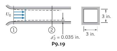
Air flows in the entrance region of a square duct, as shown. The velocity is uniform, \(U_{0}=100 \mathrm{ft} / \mathrm{s}\), and the duct is \(3 \mathrm{in}\). square. At a section \(1 \mathrm{ft}\) downstream from the entrance, the displacement thickness, \(\delta^{*}\), on each wall measures
A flow of \(68^{\circ} \mathrm{F}\) air develops in a flat horizontal duct following a well-rounded entrance section. The duct height is \(H=1 \mathrm{ft}\). Turbulent boundary layers grow on the duct walls, but the flow is not yet fully developed. Assume that the velocity profile in each boundary
A flow of air develops in a horizontal cylindrical duct, of diameter \(D=15\) in., following a well-rounded entrance. A turbulent boundary grows on the duct wall, but the flow is not yet fully developed. Assume that the velocity profile in the boundary layer is \(u / U=(y / \delta)^{1 / 7}\). The
Using numerical results for the Blasius exact solution for laminar boundary-layer flow on a flat plate, plot the dimensionless velocity profile, \(u / U\) (on the abscissa), versus dimensionless distance from the surface, \(y / \delta\) (on the ordinate). Compare with the approximate parabolic
Using numerical results obtained by Blasius (Table 9.1, on the web), evaluate the distribution of shear stress in a laminar boundary layer on a flat plate. Plot \(\tau / \tau_{w}\) versus \(y / \delta\). Compare with results derived from the approximate parabolic velocity profile given in Problem
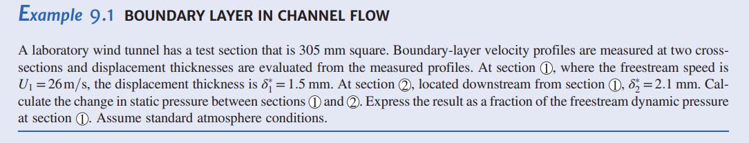
Using numerical results obtained by Blasius (Table 9.1, on the web), evaluate the vertical component of velocity in a laminar boundary layer on a flat plate. Plot \(v / U\) versus \(y / \delta\) for \(R e_{x}=10^{5}\).Data From Table 9.1 Example 9.1 BOUNDARY LAYER IN CHANNEL FLOW A laboratory wind
Consider flow of air over a flat plate. On one graph, plot the laminar boundary-layer thickness as a function of distance along the plate (up to transition) for freestream speeds \(U=1 \mathrm{~m} / \mathrm{s}, 2 \mathrm{~m} / \mathrm{s}\), \(3 \mathrm{~m} / \mathrm{s}, 4 \mathrm{~m} / \mathrm{s},
A thin flat plate, \(L=9 \mathrm{in}\). long and \(b=3 \mathrm{ft}\) wide, is installed in a water tunnel as a splitter. The freestream speed is \(U=5 \mathrm{ft} / \mathrm{s}\), and the velocity profile in the boundary layer is approximated as parabolic. Plot \(\delta, \delta^{*}\), and
For a laminar boundary layer on a flat plate, evaluate the kinetic energy lost between the free stream and any point in the boundary layer. Assume that the boundary layer is linear (see Problem 9.8) and use a control volume so that the flow rate for the oncoming flow and boundary layer are equal.
Air at atmospheric pressure and \(20^{\circ} \mathrm{C}\) flows over both sides of a flat plate that is \(0.8 \mathrm{~m}\) long and \(0.3 \mathrm{~m}\) wide at a velocity of \(5 \mathrm{~m} / \mathrm{s}\). Determine the total drag force on the plate. If the single plate is replaced by two plates
A thin flat plate is installed in a water tunnel as a splitter. The plate is \(0.3 \mathrm{~m}\) long and \(1 \mathrm{~m}\) wide. The freestream speed is \(1.6 \mathrm{~m} / \mathrm{s}\). Laminar boundary layers form on both sides of the plate. The boundary-layer velocity profile is approximated as
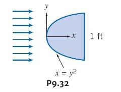
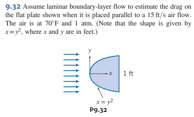
Assume laminar boundary-layer flow to estimate the drag on the flat plate shown when it is placed parallel to a \(15 \mathrm{ft} / \mathrm{s}\) air flow. The air is at \(70^{\circ} \mathrm{F}\) and \(1 \mathrm{~atm}\). (Note that the shape is given by \(x=y^{2}\), where \(x\) and \(y\) are in
A horizontal surface, with length \(L=1.8 \mathrm{~m}\) and width \(b=0.9 \mathrm{~m}\), is immersed in a stream of standard air flowing at \(U=3.2 \mathrm{~m} / \mathrm{s}\). Assume a laminar boundary layer forms and approximate the velocity profile as sinusoidal. Plot \(\delta, \delta^{*}\), and
Use the momentum integral equation to derive expressions for the displacement thickness \(\delta^{*}\), the momentum thickness \(\theta\), and the friction coefficient \(C_{f}\) for a linear velocity profile. Compare your results to those in Table 9.2. What is the percent error in the total drag on
A horizontal surface, with length \(L=0.8 \mathrm{~m}\) and width \(b=1.9 \mathrm{~m}\), is immersed in a stream of standard air flowing at \(U=5.3 \mathrm{~m} / \mathrm{s}\). Assume a laminar boundary layer forms and approximate the velocity profile as linear. Plot \(\delta, \delta^{*}\), and
Assume the flow conditions given in Example 9.3. Plot \(\delta, \delta^{*}\), and \(\tau_{w}\) versus \(x / L\) for the plate.Data From Example 9.3 Example 9.3 TURBULENT BOUNDARY LAYER ON A FLAT PLATE: APPROXIMATE SOLUTION USING -POWER VELOCITY PROFILE Water flows at U=1 m/s past a flat plate with
European InterCity Express trains operate at speeds of up to \(280 \mathrm{~km} / \mathrm{hr}\). Suppose that a train is \(120 \mathrm{~m}\) long. Treat the sides and top of the train as a smooth flat plate \(9 \mathrm{~m}\) wide. When the train moves through still air at sea level, calculate the
Repeat Problem 9.32, for an air flow at \(80 \mathrm{ft} / \mathrm{s}\), assuming a turbulent boundary layer.Data From Problem 9.32 9.32 Assume laminar boundary-layer flow to estimate the drag on the flat plate shown when it is placed parallel to a 15 ft/s air flow. The air is at 70F and 1 atm.
The U.S. Navy has built the Sea Shadow, which is a small waterplane twin-hull (SWATH) ship whose object is to achieve the same reduced radar profile as the STEALTH aircraft. This catamaran is \(160 \mathrm{ft}\) long and its twin hulls have a draft of \(14 \mathrm{ft}\). Assume that the ocean
The two rectangular smooth flat plates are to have the same drag in the same fluid stream. Calculate the required value of \(x\). If the two plates are combined into the \(\mathrm{T}\)-shape indicated, what ratio exists between the drag of the combination and that of either one? Assume laminar
Standard air flows over a horizontal smooth flat plate at freestream speed \(U=20 \mathrm{~m} / \mathrm{s}\). The plate length is \(L=1.5 \mathrm{~m}\) and its width is \(b=0.8 \mathrm{~m}\). The pressure gradient is zero. The boundary layer is tripped so that it is turbulent from the leading edge;
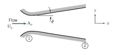
A uniform flow of standard air at \(60 \mathrm{~m} / \mathrm{s}\) enters a plane-wall diffuser with negligible boundary-layer thickness. The inlet width is \(75 \mathrm{~mm}\). The diffuser walls diverge slightly to accommodate the boundary-layer growth so that the pressure gradient is negligible.
Air flows in a cylindrical duct of diameter \(D=6\) in. At section (1), the turbulent boundary layer is of thickness \(\delta_{1}=0.4 \mathrm{in}\). and the velocity in the inviscid central core is \(U_{1}=80 \mathrm{ft} / \mathrm{s}\). Further downstream, at section (2), the boundary layer is of
Table 9.1 (on the web) shows the numerical results obtained from Blasius exact solution of the laminar boundary-layer equations. Plot the velocity distribution. On the same graph, plot the turbulent velocity distribution given by the \(\frac{1}{7}\)-power expression of Eq. 9.24. Which is most
A fluid flow enters the plane-wall diffuser that has an entrance area of \(A_{o}\) at a velocity of \(U_{o}\). (a) Assuming the fluid is inviscid, determine the velocity gradient \(\frac{d U}{d x}\) in terms of \(U_{o}\) and \(A_{o}\) for a value of \(\phi=0^{\circ}\) and \(\phi=20^{\circ}\). (b)
Boundary-layer separation occurs when the shear stress at the surface becomes zero. Assume a polynomial representation for the laminar boundary layer of the form, \(u / U=a+b \lambda+c \lambda^{2}+d \lambda^{3}\), where \(\lambda=y / \delta\). Specify boundary conditions on the velocity profile at
For flow over a flat plate with zero pressure gradient, will the shear stress increase, decrease, or remain constant along the plate? Justify your answer. Does the momentum flux increase, decrease, or remain constant as the flow proceeds along the plate? Justify your answer. Compare the behavior of
A laboratory wind tunnel has a test section that is square in cross section, with inlet width \(W_{1}\) and height \(H_{1}\), each equal to \(1 \mathrm{ft}\). At freestream speed \(U_{1}=80 \mathrm{ft} / \mathrm{s}\), measurements show the boundary-layer thickness is \(\delta_{1}=0.4\) in. with a
A flat-bottomed barge, \(80 \mathrm{ft}\) long and \(35 \mathrm{ft}\) wide, submerged to a depth of \(5 \mathrm{ft}\), is to be pushed up a river at \(60^{\circ} \mathrm{F}\). Estimate and plot the power required to overcome skin friction for speeds ranging up to \(15 \mathrm{mph}\).
A towboat for river barges is tested in a towing tank. The towboat model is built at a scale ratio of 1:13.5. Dimensions of the model are overall length \(3.5 \mathrm{~m}\), beam \(1 \mathrm{~m}\), and draft \(0.2 \mathrm{~m}\). The model displacement in fresh water is \(5500 \mathrm{~N}\).
Plot the local friction coefficient \(c_{f}\), the boundary layer thickness ratio \(\delta / x\), and the drag coefficient \(C_{f}\), for both laminar and turbulent boundary layers on a flat plate for \(\mathbf{R}_{x}\), from 0 to 500,000 , assuming in the turbulent case that the layer is tripped
A smooth plate \(3 \mathrm{~m}\) long and \(0.9 \mathrm{~m}\) wide moves through still sea level air at \(4.5 \mathrm{~m} / \mathrm{s}\). Assuming the boundary layer to be wholly laminar, calculate (a) the thickness of the layer at \(0.5,1.0,1.5,2.0\), 2.5 , and \(3.0 \mathrm{~m}\) from the leading
A nuclear submarine cruises fully submerged at 27 knots. The hull is approximately a circular cylinder with diameter \(D=11.0 \mathrm{~m}\) and length \(L=107 \mathrm{~m}\). Estimate the percentage of the hull length for which the boundary layer is laminar. Calculate the skin friction drag on the
The drag coefficient of a circular disk when placed normal to the flow is 1.12. Calculate the force and power necessary to drive a 12 in. \((0.3 \mathrm{~m})\) disk at \(48 \mathrm{~km} / \mathrm{h}\) through (a) standard air at sea level, and (b) water.
A steel sphere \((\mathrm{SG}=7.8)\) of \(13 \mathrm{~mm}\) diameter falls at a constant velocity of \(0.06 \mathrm{~m} / \mathrm{s}\) through an oil \((\mathrm{SG}=0.90)\). Calculate the viscosity of the oil, assuming that the fall occurs in a large tank.
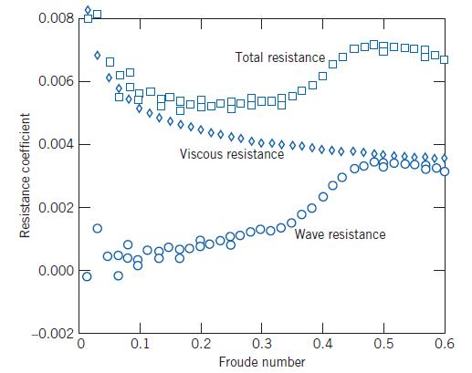
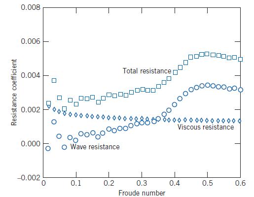
The wave resistance and viscous resistance on a model and prototype ship were discussed. For the prototype, \(L=130 \mathrm{~m}\) and \(A=1800 \mathrm{~m}^{2}\). From the data of Figs 7.2 and 7.3, plot on one graph the wave, viscous, and total resistance ( \(\mathrm{N}\) ) experienced by the
What constant speed will be attained by a lead \((\mathrm{SG}=1.4)\) sphere of \(0.5 \mathrm{in}\). diameter falling freely through an oil of kinematic viscosity \(0.12 \mathrm{ft}^{2} / \mathrm{s}\) and \(\mathrm{SG} 0.95\), if the fall occurs in a large tank?
Glass spheres of 0.1 in. diameter fall at constant velocities of 0.1 and \(0.05 \mathrm{ft} / \mathrm{s}\) through two different oils of the same specific gravity in very large tanks. If the viscosity of the first oil is \(0.002 \mathrm{lbf} \cdot \mathrm{s} / \mathrm{ft}^{2}\), what is the
As a design engineer you are asked to design an emergency braking parachute system for use with a military aircraft of mass \(9500 \mathrm{~kg}\). The plane lands at \(350 \mathrm{~km} / \mathrm{hr}\), and the parachute system alone must slow the airplane to \(100 \mathrm{~km} / \mathrm{hr}\) in
Calculate the drag of a smooth sphere of \(0.3 \mathrm{~m}\) diameter in a stream of standard sea level air at Reynolds numbers of 1,10,100, and 1000 .
A cylindrical chimney \(0.9 \mathrm{~m}\) in diameter and \(22.5 \mathrm{~m}\) high is exposed to a \(56 \mathrm{~km} / \mathrm{h}\) wind \(\left(15^{\circ} \mathrm{C}\right.\) and \(\left.101.3 \mathrm{kPa}\right)\). Estimate the bending moment at the bottom of the chimney. Neglect end effects.
Ballistic data obtained on a firing range show that aerodynamic drag reduces the speed of a .44 magnum revolver bullet from \(250 \mathrm{~m} / \mathrm{s}\) to \(210 \mathrm{~m} / \mathrm{s}\) as it travels over a horizontal distance of \(150 \mathrm{~m}\). The diameter and mass of the bullet are
A standard marine torpedo is \(0.533 \mathrm{~m}\) in diameter and about \(7.2 \mathrm{~m}\) long. Make an engineering estimate of the power required to drive this torpedo at \(80 \mathrm{~km} / \mathrm{h}\) through freshwater at \(20^{\circ} \mathrm{C}\). Assume hemispherical nose, cylindrical
A large truck has an essentially boxlike body that causes flow separation at the front edges of the cab at any speed. The drag is mostly profile drag and \(C_{D}=0.75\). If the projected frontal area of the truck is \(9 \mathrm{~m}^{2}\), determine and plot as a function of speed between zero and
At a surprise party for a friend you've tied a series of \(20-\mathrm{cm}-\) diameter helium balloons to a flagpole, each tied with a short string. The first one is tied \(1 \mathrm{~m}\) above the ground, and the other eight are tied at \(1 \mathrm{~m}\) spacings, so that the last is tied at a
Showing 200 - 300
of 1127
1
2
3
4
5
6
7
8
9
10
11
12
Step by Step Answers