New Semester
Started
Get
50% OFF
Study Help!
--h --m --s
Claim Now
Question Answers
Textbooks
Find textbooks, questions and answers
Oops, something went wrong!
Change your search query and then try again
S
Books
FREE
Study Help
Expert Questions
Accounting
General Management
Mathematics
Finance
Organizational Behaviour
Law
Physics
Operating System
Management Leadership
Sociology
Programming
Marketing
Database
Computer Network
Economics
Textbooks Solutions
Accounting
Managerial Accounting
Management Leadership
Cost Accounting
Statistics
Business Law
Corporate Finance
Finance
Economics
Auditing
Tutors
Online Tutors
Find a Tutor
Hire a Tutor
Become a Tutor
AI Tutor
AI Study Planner
NEW
Sell Books
Search
Search
Sign In
Register
study help
engineering
mechanical vibration analysis
Mechanical Vibrations 6th Edition Singiresu S Rao - Solutions
The central difference approximation of \(d x / d t\) at \(t_{i}\) is given bya. \(\frac{1}{2 h}\left(x_{i+1}-x_{i}\right)\)b. \(\frac{1}{2 h}\left(x_{i}-x_{i-1}\right)\)c. \(\frac{1}{2 h}\left(x_{i+1}-x_{i-1}\right)\)
The central difference approximation of \(d^{2} x / d t^{2}\) at \(t_{i}\) is given bya. \(\frac{1}{h^{2}}\left(x_{i+1}-2 x_{i}+x_{i-1}\right)\)b. \(\frac{1}{h^{2}}\left(x_{i+1}-x_{i-1}\right)\)c. \(\frac{1}{h^{2}}\left(x_{i}-x_{i-1}\right)\)
An integration method in which the computation of \(x_{i+1}\) is based on the equilibrium equation at \(t_{i}\) is known asa. explicit methodb. implicit methodc. regular method
In a non-self-starting method, we need to generate the value of the following quantity using the finite difference approximations of \(\dot{x}_{i}\) and \(\ddot{x}_{i}\) :a. \(\dot{x}_{-1}\)b. \(\ddot{x}_{-1}\)c. \(x_{-1}\)
Runge-Kutta methods find the approximate solutions ofa. algebraic equationsb. differential equationsc. matrix equations
The finite difference approximation of \(d^{2} U / d x^{2}+\alpha^{2} U=0\) at \(x_{i}\) is given bya. \(U_{i+1}-\left(2-h^{2} \alpha^{2}\right) U_{i}+U_{i-1}=0\)b. \(U_{i+1}-2 U_{i}+U_{i+1}=0\)c. \(U_{i+1}-\left(2-\alpha^{2}\right) U_{i}+U_{i-1}=0\)
The forward difference formulas make use of the values of the function to the right of the base grid point. Thus the first derivative at point \(i\left(t=t_{i}\right)\) is defined as\[\frac{d x}{d t}=\frac{x(t+\Delta t)-x(t)}{\Delta t}=\frac{x_{i+1}-x_{i}}{\Delta t}\]Derive the forward difference
The backward difference formulas make use of the values of the function to the left of the base grid point. Accordingly, the first derivative at point \(i\left(t=t_{i}\right)\) is defined as\[\frac{d x}{d t}=\frac{x(t)-x(t-\Delta t)}{\Delta t}=\frac{x_{i}-x_{i-1}}{\Delta t}\]Derive the backward
Derive the formula for the fourth derivative, \(\left(d^{4} x\right) /\left(d t^{4}\right)\), according to the central difference method.
Find the free vibratory response of an undamped single-degree-of-freedom system with \(m=1\) and \(k=1\), using the central difference method. Assume \(x_{0}=0\) and \(\dot{x}_{0}=1\). Compare the results obtained with \(\Delta t=1\) and \(\Delta t=0.5\) with the exact solution \(x(t)=\sin t\).
Integrate the differential equation\[-\frac{d^{2} x}{d t^{2}}+0.1 x=0 \quad \text { for } \quad 0 \leq t \leq 10\]using the backward difference formula with \(\Delta t=1\). Assume the initial conditions as \(x_{0}=1\) and \(\dot{x}_{0}=0\).
Find the free-vibration response of a viscously damped single-degree-of-freedom system with \(m=k=c=1\), using the central difference method. Assume that \(x_{0}=0, \dot{x}_{0}=1\), and \(\Delta t=0.5\).
Solve Problem 11.6 by changing \(c\) to 2 .Data From Problem 11.6:-Find the free-vibration response of a viscously damped single-degree-of-freedom system with \(m=k=c=1\), using the central difference method. Assume that \(x_{0}=0, \dot{x}_{0}=1\), and \(\Delta t=0.5
How do you solve a finite element problem having symmetry in geometry and loading by modeling only half of the problem?
Why is the finite element approach presented in this chapter called the displacement method?
What is a consistent-mass matrix?
What is a lumped-mass matrix?
What is the difference between the finite element method and the Rayleigh-Ritz method?
How is the distributed load converted into an equivalent joint force vector in the finite element method?
True or False.The lumped-mass matrices are always diagonal.
True or False.The coordinate transformation of element matrices is required for all systems.
True or False.The element stiffness matrix in the global coordinate system, \([\bar{k}]\), can be expressed in terms of the local matrix \([k]\) and the coordinate transformation matrix \([\lambda]\) as \([\lambda]^{T}[k][\lambda]\).
True or False.The derivation of system matrices involves the assembly of element matrices.
True or False.Boundary conditions are to be imposed to avoid rigid-body motion of the system.
Fill in the Blank.For a thin beam element, the shape functions are assumed to be polynomials of degree _________ .
Fill in the Blank.In the displacement method, the ___________ of elements is directly approximated.
Fill in the Blank.If the displacement model used in the derivation of the element stiffness matrices is also used to derive the element mass matrices, the resulting mass matrix is called ____________ mass matrix.
Fill in the Blank.If the mass matrix is derived by assuming point masses at node points, the resulting mass matrix is called ___________ mass matrix.
Fill in the Blank.The lumped-mass matrices do not consider _____________ the coupling between the various displacement degrees of freedom of the element.
Fill in the Blank.Different orientations of finite elements require ____________ of element matrices.
The finite element method is similar toa. Rayleigh's methodb. the Rayleigh-Ritz methodc. the Lagrange method
The lumped-mass matrix of a bar element is given bya. \(ho A l\left[\begin{array}{ll}1 & 0 \\ 0 & 1\end{array}\right]\)b. \(\frac{ho A l}{6}\left[\begin{array}{ll}2 & 1 \\ 1 & 2\end{array}\right]\)c. \(\frac{ho A l}{2}\left[\begin{array}{ll}1 & 0 \\ 0 & 1\end{array}\right]\)
The element mass matrix in the global coordinate system, \([\bar{m}]\), can be expressed in terms of the element mass matrix in local coordinate system \([\mathrm{m}]\) and the coordinate transformation matrix \([\lambda]\) asa. \([\bar{m}]=[\lambda]^{T}[m]\)b. \([\bar{m}]=[m][\lambda]\)c.
Natural frequency of steel bar given bya. \(58554 \mathrm{rad} / \mathrm{s}\) lumped-mass matricesb. \(33806 \mathrm{rad} / \mathrm{s}\) consistent-mass matricesc. \(33758 \mathrm{rad} / \mathrm{s}\)d. \(58471 \mathrm{rad} / \mathrm{s}\)Assume a fixed-fixed bar with one middle node:Element
Natural frequency of aluminum bar given by consistent-mass matricesa. \(58554 \mathrm{rad} / \mathrm{s}\) lumped-mass matricesb. \(33806 \mathrm{rad} / \mathrm{s}\) consistent-mass matricesc. \(33758 \mathrm{rad} / \mathrm{s}\)d. \(58471 \mathrm{rad} / \mathrm{s}\)Assume a fixed-fixed bar with one
Natural frequency of steel bar given bya. \(58554 \mathrm{rad} / \mathrm{s}\) lumped-mass matricesb. \(33806 \mathrm{rad} / \mathrm{s}\) consistent-mass matricesc. \(33758 \mathrm{rad} / \mathrm{s}\)d. \(58471 \mathrm{rad} / \mathrm{s}\)Assume a fixed-fixed bar with one middle node:Element
Natural frequency of aluminum bar givena. \(58554 \mathrm{rad} / \mathrm{s}\) lumped-mass matricesb. \(33806 \mathrm{rad} / \mathrm{s}\) consistent-mass matricesc. \(33758 \mathrm{rad} / \mathrm{s}\)d. \(58471 \mathrm{rad} / \mathrm{s}\)Assume a fixed-fixed bar with one middle node:Element
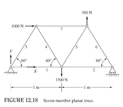
A seven-member planar truss (with pin joints) is shown in Fig. 12.18. Each of the seven members has an area of cross section of \(4 \mathrm{~cm}^{2}\) and a Young's modulus of \(207 \mathrm{GPa}\).a. Label the complete set of local and global nodal displacement degrees of freedom of the truss.
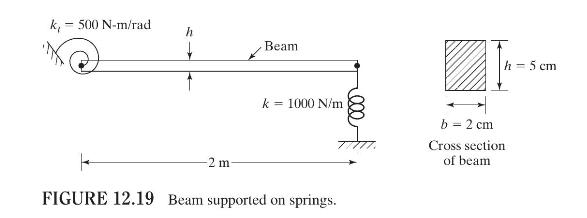
Find the stiffness and mass matrices of the beam supported on springs as shown in Fig. 12.19. Model the beam using one finite element. Assume the material of the beam as steel with a Young's modulus of \(207 \mathrm{GPa}\) and weight density of \(7650 \mathrm{~N} / \mathrm{m}^{3}\). Neglect the
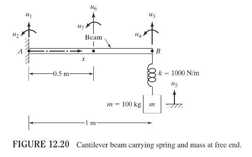
For the beam shown in Fig. 12.20, one end (point \(A\) ) is fixed and a spring-mass system is attached to the other end (point \(B\) ). Assume the cross section of the beam to be circular with radius \(2 \mathrm{~cm}\) and the material of the beam to be steel with Young's modulus of \(207
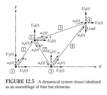
Find the global stiffness matrix of each of the four bar elements of the truss shown in Fig. 12.5 using the following data:Nodal coordinates: \(\left(X_{1}, Y_{1}\right)=(0,0) \mathrm{m},\left(X_{2}, Y_{2}\right)=(1.25,2.5) \mathrm{m},\left(X_{3}, Y_{3}\right)=(2.5,0) \mathrm{m}\), \(\left(X_{4},
For the seven-member planar truss considered in Problem 12.6 (Fig. 12.18), determine the assembled stiffness matrix of the system before applying the boundary conditions.Data From Problem 12.6:-A seven-member planar truss (with pin joints) is shown in Fig. 12.18. Each of the seven members has an
Using the result of Problem 12.9, find the assembled stiffness matrix of the truss and formulate the equilibrium equations if the vertical downward load applied at node 4 is \(5 \mathrm{kN}\).Data From Problem 12.9:-Find the global stiffness matrix of each of the four bar elements of the truss
For the beam considered in Problem 12.8 (Fig. 12.20), derive the assembled stiffness and mass matrices of the system.Data From Problem 12.8:-For the beam shown in Fig. 12.20, one end (point \(A\) ) is fixed and a spring-mass system is attached to the other end (point \(B\) ). Assume the cross
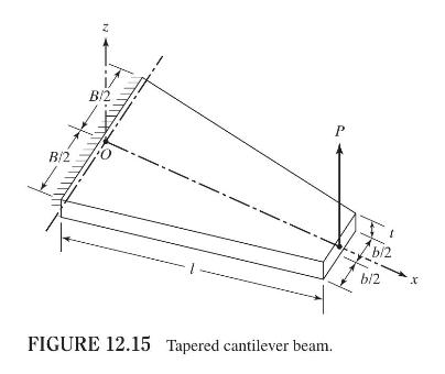
For the tapered beam considered in Problem 12.3 (Fig. 12.15), find the stress induced in the beam using a one-element idealization.Data From Problem 12.3:-The tapered cantilever beam shown in Fig. 12.15 is used as a spring to carry a load \(P\). Derive the stiffness matrix of the beam using a
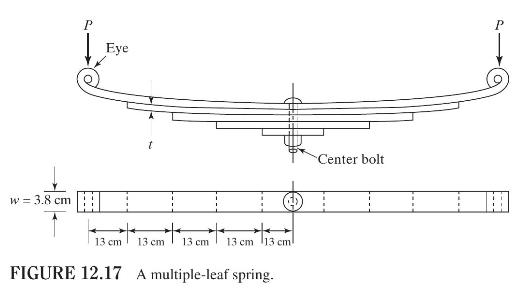
For the multiple-leaf spring described in Problem 12.5 (Fig. 12.17), consider only one-half of the spring for modeling using five beam elements of equal length and derive the stiffness and mass matrices of each of the five beam elements. The Young's modulus is \(200 \mathrm{GPa}\) and the density
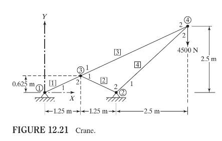
Find the nodal displacements of the crane shown in Fig. 12.21 when a vertically downward load of \(4500 \mathrm{~N}\) is applied at node 4 . The Young's modulus is \(200 \mathrm{GPa}\) and the cross- sectional area is \(13 \times 10^{-4} \mathrm{~m}^{2}\) for elements 1 and 2 and \(6.5 \times
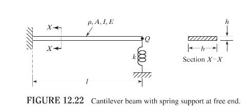
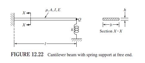
Find the tip deflection of the cantilever beam shown in Fig. 12.22 when a vertical load of \(P=500 \mathrm{~N}\) is applied at point \(Q\) using (a) a one-element approximation and (b) a two-element approximation. Assume \(l=0.25 \mathrm{~m}, h=25 \mathrm{~mm}, b=50 \mathrm{~mm}, E=2.07 \times
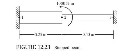
Find the stresses in the stepped beam shown in Fig. 12.23 when a moment of \(1000 \mathrm{~N}-\mathrm{m}\) is applied at node 2 using a two-element idealization. The beam has a square cross section \(50 \mathrm{~mm} \times 50 \mathrm{~mm}\) between nodes 1 and 2 and \(25 \mathrm{~mm} \times 25
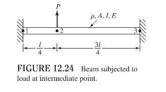
Find the transverse deflection and slope of node 2 of the beam shown in Fig. 12.24 using a two-element idealization. Compare the solution with that of simple beam theory. P 2 P.A.I.E 31 3 FIGURE 12.24 Beam subjected to load at intermediate point.
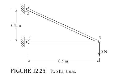
Find the displacement of node 3 and the stresses in the two members of the truss shown in Fig. 12.25. Assume that the Young's modulus and the cross-sectional areas of the two members are the same with \(E=200 \mathrm{GPa}\) and \(A=0.5 \times 10^{-3} \mathrm{~m}^{2}\). 0.2 m NY 3 0.5 m FIGURE 12.25
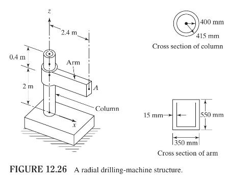
A simplified model of a radial drilling machine is shown in Fig. 12.26. If a vertical force of \(5000 \mathrm{~N}\) along the \(z\)-direction and a bending moment of \(500 \mathrm{~N}-\mathrm{m}\) in the \(x z\)-plane are developed at point \(A\) during a metal cutting operation, find the stresses
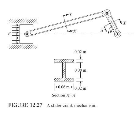
The crank in the slider-crank mechanism shown in Fig. 12.27 rotates at a constant clockwise angular speed of \(1000 \mathrm{rpm}\). Find the stresses in the connecting rod and the crank when the pressure acting on the piston is \(1 \mathrm{MPa}\) and \(\theta=30^{\circ}\). The diameter of the
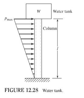
A water tank of mass \(W\) is supported by a hollow circular steel column of inner diameter \(d\), wall thickness \(t\), and height \(l\). The wind pressure acting on the column can be assumed to vary linearly from 0 to \(p_{\max }\) as shown in Fig. 12.28. Find the bending stress induced in the
For the seven-member planar truss considered in Problem 12.6 (Fig. 12.18), determine the following:a. The system stiffness matrix after applying the boundary conditions.b. The nodal displacements of the truss under the loads indicated in Fig. 12.18.Data From Problem 12.6:-A seven-member planar
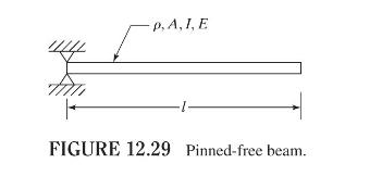
Using one beam element, find the natural frequencies of the uniform pinned-free beam shown in Fig. 12.29. p. A, I, E FIGURE 12.29 Pinned-free beam.
Using one beam element and one spring element, find the natural frequencies of the uniform, spring-supported cantilever beam shown in Fig. 12.22.Figure 12.22:- p. A,I,E X X+ 7777 b Section X-X h FIGURE 12.22 Cantilever beam with spring support at free end.
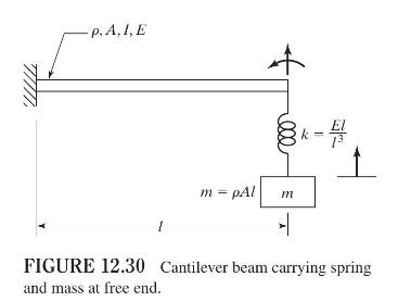
Using one beam element and one spring element, find the natural frequencies of the system shown in Fig. 12.30. p. A,I,E 8k - El m = pAl m FIGURE 12.30 Cantilever beam carrying spring and mass at free end.
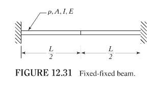
Using two beam elements, find the natural frequencies and mode shapes of the uniform fixedfixed beam shown in Fig. 12.31. p. A, I, E L 2 L 2 FIGURE 12.31 Fixed-fixed beam.
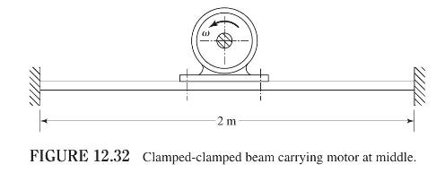
An electric motor, of mass \(m=100 \mathrm{~kg}\) and operating speed \(=1800 \mathrm{rpm}\), is fixed at the middle of a clamped-clamped steel beam of rectangular cross section, as shown in Fig. 12.32. Design the beam such that the natural frequency of the system exceeds the operating speed of the
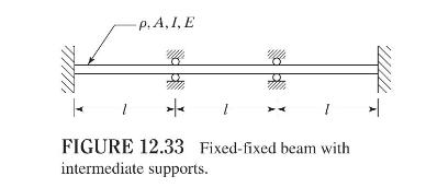
Find the natural frequencies of the beam shown in Fig. 12.33, using three finite elements of length \(l\) each. p. A, I, E + FIGURE 12.33 Fixed-fixed beam with intermediate supports.
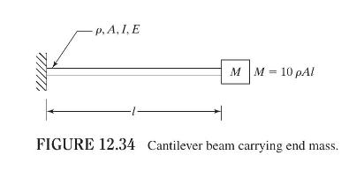
Find the natural frequencies of the cantilever beam carrying an end mass \(M\) shown in Fig. 12.34, using a one-beam element idealization. p. A, I. E MM 10 pAl FIGURE 12.34 Cantilever beam carrying end mass.
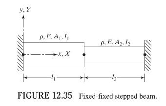
Find the natural frequencies of vibration of the beam shown in Fig. 12.35, using two beam elements. Also find the load vector if a uniformly distributed transverse load \(p\) is applied to element 1. y. Y p. E. A p. E, A2, 12 x. X FIGURE 12.35 Fixed-fixed stepped beam.
Find the natural frequencies of a beam of length \(l\), which is pin connected at \(x=0\) and fixed at \(x=l\), using one beam element.
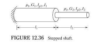
Find the natural frequencies of torsional vibration of the stepped shaft shown in Fig. 12.36. Assume that \(ho_{1}=ho_{2}=ho, G_{1}=G_{2}=G, I_{p 1}=2 I_{p 2}=2 I_{p}, J_{1}=2 J_{2}=2 J\), and \(l_{1}=l_{2}=l\). P1. G.11 P2, G2, 1p2:12 + -h FIGURE 12.36 Stepped shaft.
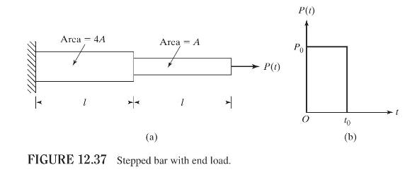
Find the dynamic response of the stepped bar shown in Fig. 12.37(a) when its free end is subjected to the load given in Fig. 12.37(b). P(t) Arca - 4A Area A Po P(1) (a) FIGURE 12.37 Stepped bar with end load. (b) 1+
Find the natural frequencies of a cantilever beam of length \(l\), cross-sectional area \(A\), moment of inertia \(I\), Young's modulus \(E\), and density \(ho\), using one finite element.
Find the natural frequencies of vibration of the radial drilling machine considered in Problem 12.20 (Fig. 12.26).Data From Problem 12.20:-A simplified model of a radial drilling machine is shown in Fig. 12.26. If a vertical force of \(5000 \mathrm{~N}\) along the \(z\)-direction and a bending
Find the natural frequencies of the water tank considered in Problem 12.22 (Fig. 12.28) using a one-beam element idealization.Data From Problem 12.22:-A water tank of mass \(W\) is supported by a hollow circular steel column of inner diameter \(d\), wall thickness \(t\), and height \(l\). The wind
Find the natural frequencies of vibration of the beam considered in Problem 12.7 using one finite element (Fig. 12.19).Data From Problem 12.7:-Find the stiffness and mass matrices of the beam supported on springs as shown in Fig. 12.19. Model the beam using one finite element. Assume the material
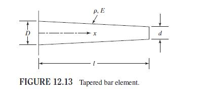
Derive the consistent- and lumped-mass matrices of the tapered bar element (which deforms in the axial direction) shown in Fig. 12.13. The diameter of the bar decreases from \(D\) to \(d\) over its length.Figure 12.13:- P.E D x d FIGURE 12.13 Tapered bar element.
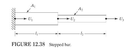
Find the natural frequencies of the stepped bar shown in Fig. 12.38 with the following data using consistent- and lumped-mass matrices: \(A_{1}=0.001 \mathrm{~m}^{2}, A_{2}=0.0006 \mathrm{~m}^{2}\), \(E=200 \mathrm{GPa}, ho_{w}=7750 \mathrm{~kg} / \mathrm{m}^{3}\), and \(l_{1}=l_{2}=1
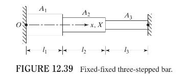
Find the undamped natural frequencies of longitudinal vibration of the stepped bar shown in Fig. 12.39 with the following data using consistent- and lumped-mass matrices: \(l_{1}=l_{2}=l_{3}=0.2 \mathrm{~m}, \quad A_{1}=2 A_{2}=4 A_{3}=0.4 \times 10^{-3} \mathrm{~m}^{2}, E=2.1 \times 10^{11}
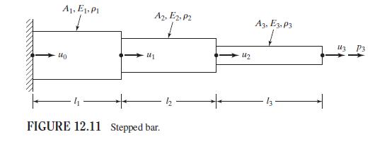
Consider the stepped bar shown in Fig. 12.11 with the following data: \(A_{1}=25 \times 10^{-4} \mathrm{~m}^{2}\), \(A_{2}=16 \times 10^{-4} \mathrm{~m}^{2}, A_{3}=9 \times 10^{-4} \mathrm{~m}^{2}, E_{i}=2 \times 10^{11} \mathrm{~Pa}, i=1,2,3, ho_{i}=7.8 \times 10^{3} \mathrm{~kg} /
Using MATLAB, find the natural frequencies and mode shapes of the stepped bar described in Problem 12.42.Data From Problem 12.42:-Consider the stepped bar shown in Fig. 12.11 with the following data: \(A_{1}=25 \times 10^{-4} \mathrm{~m}^{2}\), \(A_{2}=16 \times 10^{-4} \mathrm{~m}^{2}, A_{3}=9
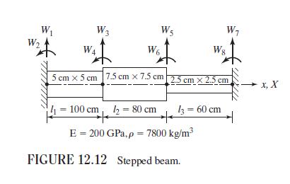
Use Program17.m to find the natural frequencies of a fixed-fixed stepped beam, similar to the one shown in Fig. 12.12, with the following data:Cross sections of elements: \(1,2,3: 0.1 \mathrm{~m} \times 0.1 \mathrm{~m}, 0.08 \mathrm{~m} \times 0.08 \mathrm{~m}, 0.05 \mathrm{~m} \times 0.05
Write a computer program for finding the assembled stiffness matrix of a general planar truss.
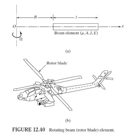
Derive the stiffness and mass matrices of a uniform beam element in transverse vibration rotating at an angular velocity of \(\Omega \mathrm{rad} / \mathrm{s}\) about a vertical axis as shown in Fig. 12.40(a). Using these matrices, find the natural frequencies of transverse vibration of the rotor
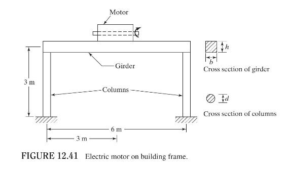
An electric motor of mass \(500 \mathrm{~kg}\) operates on the first floor of a building frame that can be modeled by a steel girder supported by two reinforced concrete columns, as shown in Fig. 12.41. If the operating speed of the motor is \(1500 \mathrm{rpm}\), design the girder and the columns
How do you recognize a nonlinear vibration problem?
What are the various sources of nonlinearity in a vibration problem?
What is the source of nonlinearity in Duffing's equation?
How is the frequency of the solution of Duffing's equation affected by the nature of the spring?
What are subharmonic oscillations?
Explain the jump phenomenon.
What principle is used in the Ritz-Galerkin method?
Define these terms: phase plane, trajectory, singular point, phase velocity.
What is the method of isoclines?
What is the difference between a hard spring and a soft spring?
Explain the difference between subharmonic and superharmonic oscillations.
What is a secular term?
Give an example of a system that leads to an equation of motion with time-dependent coefficients.
Explain the significance of the following: stable node, unstable node, saddle point, focus, and center.
What is a limit cycle?
Give two examples of physical phenomena that can be represented by van der Pol's equation.
True or False.Nonlinearity can be introduced into the governing differential equation through mass, springs, and/or dampers.
True or False.Nonlinear analysis of a system can reveal several unexpected phenomena.
True or False.The Mathieu equation is an autonomous equation.
True or False.A singular point corresponds to a state of equilibrium of the system.
True or False.The jump phenomenon is exhibited by both linear and nonlinear systems.
Showing 600 - 700
of 2655
1
2
3
4
5
6
7
8
9
10
11
12
13
14
15
Last
Step by Step Answers