New Semester
Started
Get
50% OFF
Study Help!
--h --m --s
Claim Now
Question Answers
Textbooks
Find textbooks, questions and answers
Oops, something went wrong!
Change your search query and then try again
S
Books
FREE
Study Help
Expert Questions
Accounting
General Management
Mathematics
Finance
Organizational Behaviour
Law
Physics
Operating System
Management Leadership
Sociology
Programming
Marketing
Database
Computer Network
Economics
Textbooks Solutions
Accounting
Managerial Accounting
Management Leadership
Cost Accounting
Statistics
Business Law
Corporate Finance
Finance
Economics
Auditing
Tutors
Online Tutors
Find a Tutor
Hire a Tutor
Become a Tutor
AI Tutor
AI Study Planner
NEW
Sell Books
Search
Search
Sign In
Register
study help
engineering
mechanical vibration analysis
Mechanical Vibrations 6th Edition Singiresu S Rao - Solutions
Fill in the Blank.Vibration neutralizer is also known as dynamic vibration ____________.
Control natural frequencya. Introduce dampingb. Use vibration isolatorc. Add vibration absorberd. Avoid resonance
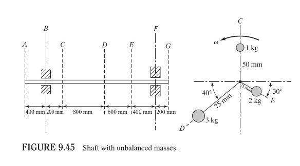
Masses of \(1 \mathrm{~kg}, 3 \mathrm{~kg}\), and \(2 \mathrm{~kg}\) are located at radii \(50 \mathrm{~mm}, 75 \mathrm{~mm}\), and \(25 \mathrm{~mm}\) in the planes \(C, D\), and \(E\), respectively, on a shaft supported at the bearings \(B\) and \(F\), as shown in Fig. 9.45. Find the masses and
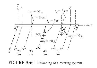
Figure 9.46 shows a rotating system in which the shaft is supported in bearings at \(A\) and \(B\). The three masses \(m_{1}, m_{2}\), and \(m_{3}\) are connected to the shaft as indicated in the figure.(a) Find the bearing reactions at \(A\) and \(B\) if the speed of the shaft is \(1000
Reduce transmission of excitation force from one part to anothera. Introduce dampingb. Use vibration isolatorc. Add vibration absorberd. Avoid resonance
Is the shaking force proportional to the square of the speed of a machine? Does the vibratory force transmitted to the foundation increase with the speed of the machine?
Fill in the Blank.Phase marks are used in ____________ plane balancing using a vibration analyzer.
Reduce response of the systema. Introduce dampingb. Use vibration isolatorc. Add vibration absorberd. Avoid resonance
A flywheel, with a mass of \(50 \mathrm{~kg}\) and an eccentricity of \(12 \mathrm{~mm}\), is mounted at the center of a steel shaft of diameter \(25 \mathrm{~mm}\). If the length of the shaft between the bearings is \(0.75 \mathrm{~m}\) and the rotational speed of the flywheel is \(1200
Derive the expression for the stress induced in a shaft with an unbalanced concentrated mass located midway between two bearings.
Fill in the Blank.Machine errors can cause ____________ in rotating machines.
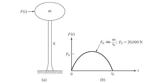
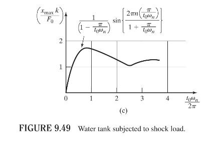
A water tank of mass \(10^{5} \mathrm{~kg}\) is supported on a reinforced cement concrete column, as shown in Fig. 9.49(a). When a projectile hits the tank, it causes a shock, in the form of a step force, asshown in Fig. 9.49(b). Determine the stiffness of the column if the maximum deflection of
An electronic instrument of mass \(20 \mathrm{~kg}\) is to be isolated from engine vibrations with frequencies ranging from \(1000 \mathrm{rpm}\) to \(3000 \mathrm{rpm}\). Find the stiffness of the undamped isolator to be used to achieve a 90 percent isolation.
In the PCB described in Problem 9.63, it is desired to reduce the displacement transmissibility to a value of 0.25. If the chassis mass is 50 percent of the mass of the PCB, determine the necessary stiffness \((k)\) and damping constant \((c)\) of the isolator if the damping ratio of the isolator
A machine with a natural frequency of \(4.2 \mathrm{~Hz}\) is subjected to a rotating unbalance force of amplitude \((F)\) of \(20 \mathrm{~N}\) at a frequency of \(4 \mathrm{~Hz}\). Design a suitable dynamic absorber for the machine assuming that the available clearance for the motion of the
Derive an expression for the displacement transmissibility of a damped single-degree-offreedom system whose base is subjected to a general periodic displacement.
An electronic instrument is to be isolated from a panel that vibrates at frequencies ranging from \(25 \mathrm{~Hz}\) to \(35 \mathrm{~Hz}\). It is estimated that at least 80 percent vibration isolation must be achieved to prevent damage to the instrument. If the instrument weights \(85
An exhaust fan, having a small unbalance, weights \(800 \mathrm{~N}\) and operates at a speed of \(600 \mathrm{rpm}\). It is desired to limit the response to a transmissibility of 2.5 as the fan passes through resonance during start-up. In addition, an isolation of 90 percent is to be achieved at
An air compressor of mass \(500 \mathrm{~kg}\) has an eccentricity of \(50 \mathrm{~kg}-\mathrm{cm}\) and operates at a speed of \(300 \mathrm{rpm}\). The compressor is to be mounted on one of the following mountings:(a) an isolator consisting of a spring with negligible damping, and(b) a shock
The armature of a variable-speed electric motor, of mass \(200 \mathrm{~kg}\), has an unbalance due to manufacturing errors. The motor is mounted on an isolator having a stiffness of \(10 \mathrm{kN} / \mathrm{m}\) and a dashpot having a damping ratio of 0.15.(a) Find the speed range over which the
A dishwashing machine weighing \(75 \mathrm{~kg}\) operates at \(300 \mathrm{rpm}\). Find the minimum static deflection of an isolator that provides 60 percent isolation. Assume that the damping in the isolator is negligible.
It is found that an exhaust fan, of mass \(80 \mathrm{~kg}\) and operating speed \(1000 \mathrm{rpm}\), produces a repeating force of \(10,000 \mathrm{~N}\) on its rigid base. If the maximum force transmitted to the base is to be limited to \(2000 \mathrm{~N}\) using an undamped isolator,
A compressor of mass \(120 \mathrm{~kg}\) has a rotating unbalance of \(0.2 \mathrm{~kg}-\mathrm{m}\). If an isolator of stiffness \(0.5 \mathrm{MN} / \mathrm{m}\) and damping ratio 0.06 is used, find the range of operating speeds of the compressor over which the force transmitted to the foundation
An internal combustion engine has a rotating unbalance of \(1.0 \mathrm{~kg}-\mathrm{m}\) and operates between \(800 \mathrm{rpm}\) and \(2000 \mathrm{rpm}\). When attached directly to the floor, it transmitted a force of \(7018 \mathrm{~N}\) at \(800 \mathrm{rpm}\) and 43,865 \(\mathrm{N}\) at
A small machine tool of mass \(100 \mathrm{~kg}\) operates at \(600 \mathrm{rpm}\). Find the static deflection of an undamped isolator that provides 90 percent isolation.
Design the suspension of a car such that the maximum vertical acceleration felt by the driver is less than \(2 g\) at all speeds between \(70 \mathrm{~km} / \mathrm{h}\) and \(140 \mathrm{~km} / \mathrm{h}\) while traveling on a road whose surface varies sinusoidally as \(y(u)=0.5 \sin 2 u
Consider a single-degree-of-freedom system with Coulomb damping (which offers a constant friction force, \(F_{c}\) ). Derive an expression for the force transmissibility when the mass is subjected to a harmonic force, \(F(t)=F_{0} \sin \omega t\).
Consider a single-degree-of-freedom system with Coulomb damping (which offers a constant friction force, \(F_{c}\) ). Derive expressions for the absolute and relative displacement transmissibilities when the base is subjected to a harmonic displacement, \(y(t)=Y \sin \omega t\).
When a washing machine, of mass \(200 \mathrm{~kg}\) and an unbalance \(0.02 \mathrm{~kg}\) - \(\mathrm{m}\), is mounted on an isolator, the isolator deflects by \(5 \mathrm{~mm}\) under the static load. Find (a) the amplitude of the washing machine and (b) the force transmitted to the foundation
An electric motor, of mass \(60 \mathrm{~kg}\), rated speed \(3000 \mathrm{rpm}\), and an unbalance \(0.002 \mathrm{~kg}\)-m, is to be mounted on an isolator to achieve a force transmissibility of less than 0.25. Determine (a) the stiffness of the isolator, (b) the dynamic amplitude of the motor,
An engine is mounted on a rigid foundation through four springs. During operation, the engine produces an excitation force at a frequency of \(3000 \mathrm{rpm}\). If the weight of the engine causes the springs to deflect by \(10 \mathrm{~mm}\), determine the reduction in the force transmitted to
A printed circuit board of mass \(1 \mathrm{~kg}\) is supported to the base through an undamped isolator. During shipping, the base is subjected to a harmonic disturbance (motion) of amplitude \(2 \mathrm{~mm}\) and frequency \(2 \mathrm{~Hz}\). Design the isolator so that the displacement
An electronic instrument of mass \(10 \mathrm{~kg}\) is mounted on an isolation pad. If the base of the isolation pad is subjected to a shock in the form of a step velocity of \(10 \mathrm{~mm} / \mathrm{s}\), find the stiffness of the isolation pad if the maximum permissible values of deflection
A viscously damped single-degree-of-freedom system has a body of mass \(25 \mathrm{~kg}\) with a spring constant of \(70 \mathrm{kN} / \mathrm{m}\). Its base is subjected to harmonic vibration.(a) When the base vibrates with an amplitude of \(50 \mathrm{~mm}\) at resonance, the steady-state
A single-degree-of-freedom system is used to represent an automobile, of mass \(m\), damping constant \(c\), and stiffness \(k\), which travels on a rough road that is in the form of a sinusoidal surface with an amplitude \(Y\) and wavelength \(l\). If the automobile travels at a velocity \(v\),
A sensitive instrument of mass \(100 \mathrm{~kg}\) is installed at a location that is subjected to harmonic motion with frequency \(20 \mathrm{~Hz}\) and acceleration \(0.5 \mathrm{~m} / \mathrm{s}^{2}\). If the instrument is supported on an isolator having a stiffness \(k=25 \times 10^{4}
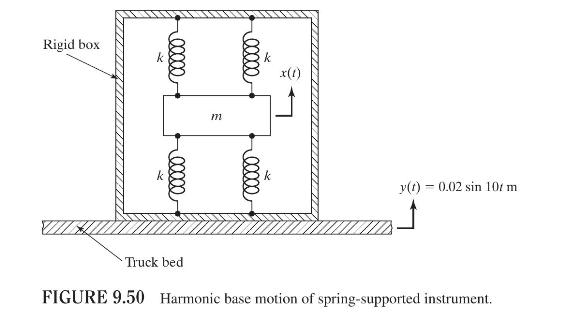
A delicate instrument weighing \(200 \mathrm{~N}\) is suspended by four identical springs, each with stiffness \(50,000 \mathrm{~N} / \mathrm{m}\), in a rigid box as shown in Fig. 9.50. The box is transported by a truck. If the truck is subjected to a vertical harmonic motion given by \(y(t)=0.02
A damped torsional system is composed of a shaft and a rotor (disk). The torsional stiffness and the torsional damping constant of the shaft are given by \(k_{t}=6000 \mathrm{~N}-\mathrm{m} / \mathrm{rad}\) and \(c_{t}=100 \mathrm{~N}-\mathrm{m}-\mathrm{s} / \mathrm{rad}\). The mass moment of
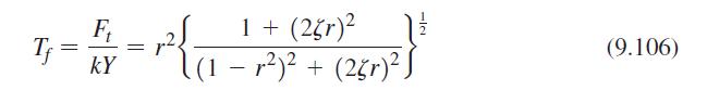
The force transmissibility of a damped single-degree-of-freedom system with base motion is given by Eq. (9.106):\[T_{f}=\frac{F_{t}}{k Y}=r^{2}\left\{\frac{1+(2 \zeta r)^{2}}{\left(1-r^{2}\right)^{2}+(2 \zeta r)^{2}}\right\}^{\frac{1}{2}}\]where \(F_{t}\) is the magnitude of the force transmitted
Derive an expression for the relative displacement transmissibility, \(\frac{Z}{Y}\), where \(Z=X-Y\), for a damped single-degree-of-freedom system subjected to the base motion, \(y(t)=Y \sin \omega t\).
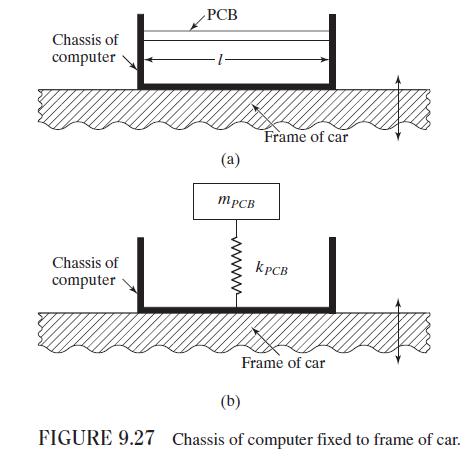
A printed circuit board (PCB), made of fiber reinforced plastic composite material, is attached to a chassis that is attached to a motor vibrating at a speed of \(3000 \mathrm{rpm}\). The PCB can be modeled as a fixed-fixed beam, similar to the one shown in Fig. 9.27, with a length (l) \(20
An air compressor of mass \(200 \mathrm{~kg}\), with an unbalance of \(0.01 \mathrm{~kg}-\mathrm{m}\), is found to have a large amplitude of vibration while running at \(1200 \mathrm{rpm}\). Determine the mass and spring constant of the absorber to be added if the natural frequencies of the system
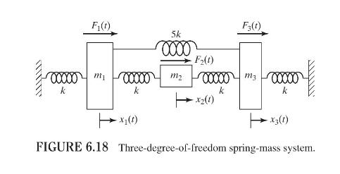
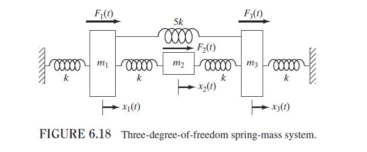
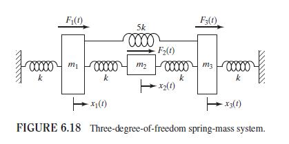
Derive the equations of motion, using Newton's second law of motion, for each of the systems shown in Figs. 6.18. F(t) 5k 00000 mi k F3(1) F2(t) 00000 m2 m3 00000 k k X2(1) k x(1) (1)Ex FIGURE 6.18 Three-degree-of-freedom spring-mass system.
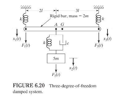
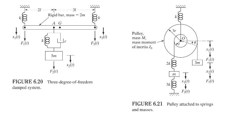
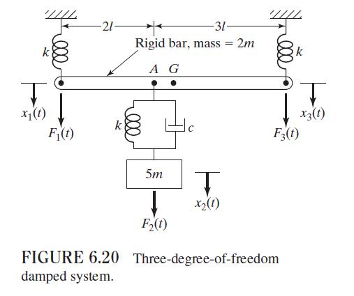
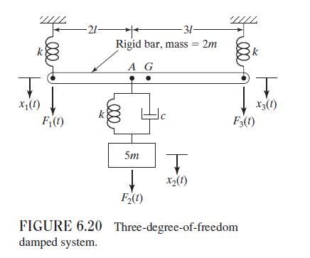
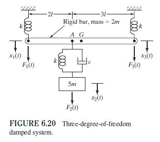
Derive the equations of motion, using Newton's second law of motion, for each of the systems shown in Figs. 6.20. 000 x(t) F(t) 21 31 Rigid bar, mass - 2m A G k X3(1) F3(1) 5m x2(1) F2(t) FIGURE 6.20 Three-degree-of-freedom damped system.
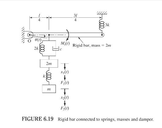
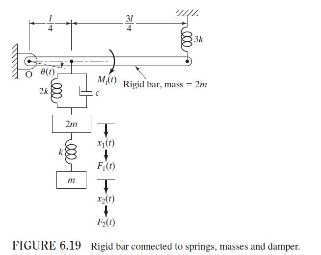
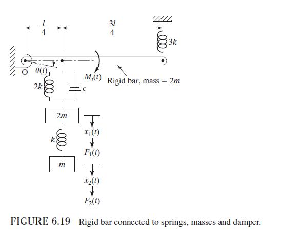
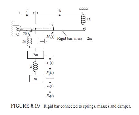
Derive the equations of motion, using Newton's second law of motion, for each of the systems shown in Figs. 6.19. 8(t) 2k 2m k 4 M,(t) 000 3k Free Rigid bar, mass = 2m T x(1) F(t) m I X2(1) t F(1) FIGURE 6.19 Rigid bar connected to springs, masses and damper.
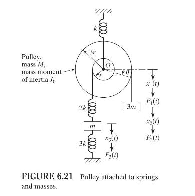
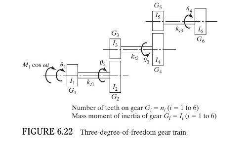
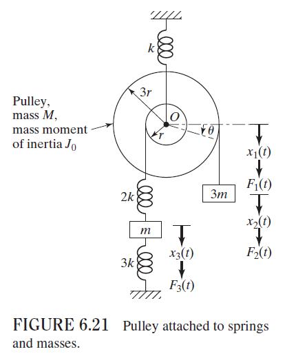
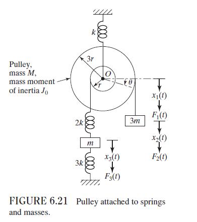
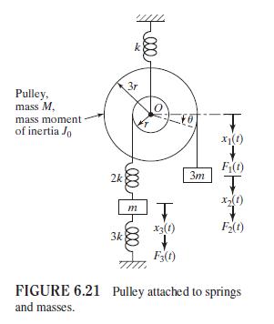
Derive the equations of motion, using Newton's second law of motion, for each of the systems shown in Figs. 6.21. Pulley, mass M, mass moment of inertia Jo 3r 3m T x(1) F(t) 2k 000 T x2(1) m T X3(1) F2(1) 3k F3(t) FIGURE 6.21 Pulley attached to springs and masses.
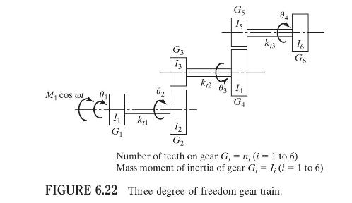
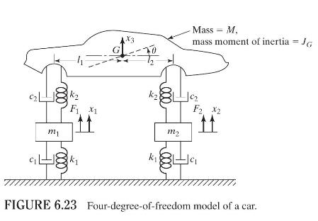
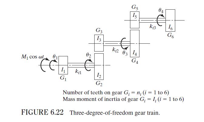
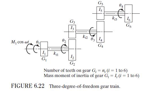
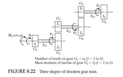
Derive the equations of motion, using Newton's second law of motion, for each of the systems shown in Figs. 6.22. M, cos wt G 15 G3 13 ka 03 4 kn 12 G k3 16 G6 G Number of teeth on gear G, n, (i = 1 to 6) Mass moment of inertia of gear G = 1, (i = 1 to 6) FIGURE 6.22 Three-degree-of-freedom gear
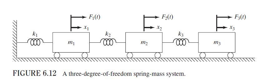
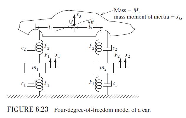
A car is modeled as shown in Fig. 6.23. Derive the equations of motion using Newton's second law of motion.Figure 6.23:- x(t) F(t) 21 31 Rigid bar, mass- 2m A G X3(1) F3(t) 5m x2(1) F(t) FIGURE 6.20 Three-degree-of-freedom damped system. Pulley, mass M, mass moment of inertia Jo 2k -000 3r k 3m T
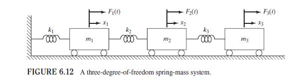
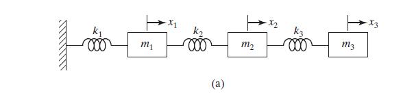
The equations of motion derived using the displacements of the masses, \(x_{1}, x_{2}\), and \(x_{3}\) as degrees of freedom in Fig. 6.12 (Example 6.10) lead to symmetric mass and stiffness matrices in Eq. (E.3) of Example 6.10. Express the equations of motion, (E.3) of Example 6.10, using \(x_{1},
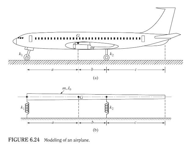
A simplified vibration analysis of an airplane considers bounce and pitch motions (Fig. 6.24(a)). For this, a model consisting of a rigid bar (corresponding to the body of the airplane) supported on two springs (corresponding to the stiffnesses of the main and nose landing gears) as shown in Fig.
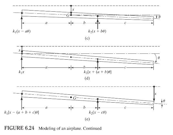
Consider the two-degree-of-freedom system shown in Fig. 6.25 with \(m_{1}=m_{2}=1\) and \(k_{1}=k_{2}=4\). The masses \(m_{1}\) and \(m_{2}\) move on a rough surface for which the equivalent viscous damping constants can be assumed as \(c_{1}=c_{2}=2\).a. Derive the equations of motion of the
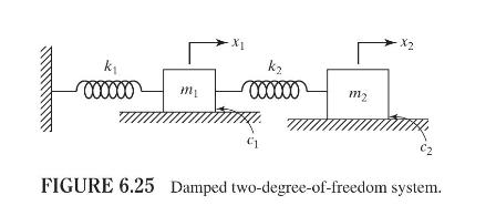
A simplified model of the main landing gear system of a small airplane is shown in Fig. 6.27 with \(m_{1}=100 \mathrm{~kg}, m_{2}=5000 \mathrm{~kg}, k_{1}=10^{4} \mathrm{~N} / \mathrm{m}\), and \(k_{2}=10^{6} \mathrm{~N} / \mathrm{m}\).a. Find the equations of motion of the system.b. Find the
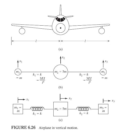
For a simplified analysis of the vibration of an airplane in the vertical direction, a threedegree-of-freedom model, as shown in Fig. 6.26, can be used. The three masses indicate the masses of the two wings \(\left(m_{1}=m_{3}=m\right)\) and the fuselage \(\left(m_{2}=5 m\right)\). The
Derive the stiffness matrix of each of the systems shown in Figs. 6.18 using the indicated coordinates. F(t) 5k 0000 m2 F2(t) m1 k k x1(t) F3(t) 00000 m3 k k x(1) X3(1) FIGURE 6.18 Three-degree-of-freedom spring-mass system.
Derive the stiffness matrix of each of the systems shown in Figs. 6.19 using the indicated coordinates. 31 4 4 3k O 8(t) 2k M,(t) Rigid bar, mass= 2m C 2m x1(t) F(t) m T x2(t) F2(t) FIGURE 6.19 Rigid bar connected to springs, masses and damper.
Derive the stiffness matrix of each of the systems shown in Figs. 6.20 using the indicated coordinates. k x1(t) -21- 31 Rigid bar, mass = 2m A G k F(t) k F3(t) 5m T x2(t) F2(t) FIGURE 6.20 Three-degree-of-freedom damped system. X3(1)
Derive the stiffness matrix of each of the systems shown in Figs.6.21 using the indicated coordinates. Pulley, mass M, mass moment of inertia Jo 2k k 3r 000 0 3m x1(t) F(t) I x2(t) m T x3(t) F2(t) 3k F3(1) FIGURE 6.21 Pulley attached to springs and masses.
Derive the stiffness matrix of each of the systems shown in Figs. 6.22 using the indicated coordinates. G5 04 15 16 G3 G6 13 k12 03. 14 02 M cos wot G4 11 12 G G2 Number of teeth on gear G = n; (i = 1 to 6) Mass moment of inertia of gear G = I (i = 1 to 6) FIGURE 6.22 Three-degree-of-freedom gear
Derive the stiffness matrix of each of the systems shown in Figs. 6.23 using the indicated coordinates. 4 G X3 Mass = M, mass moment of inertia = JG m1 k2 F1 X1 11 k F2 X2 11 m2 k C1 C1 k FIGURE 6.23 Four-degree-of-freedom model of a car.
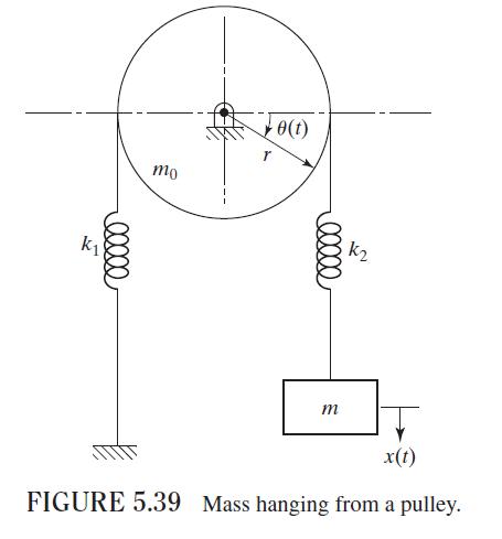
Derive the flexibility matrix of the system shown in Fig. 5.39. mo e(t) ellee k1 k2 lllll m x(t) FIGURE 5.39 Mass hanging from a pulley.
Derive the stiffness matrix of the system shown in Fig. 5.39. mo e(t) ellee k1 k2 lllll m x(t) FIGURE 5.39 Mass hanging from a pulley.
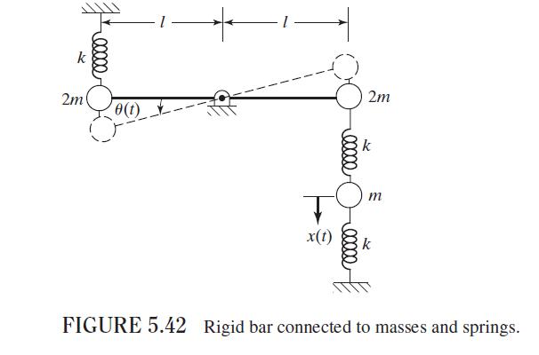
Derive the flexibility matrix of the system shown in Fig. 5.42. 00000 2m 8(t) * 2m ellee x(t) m 00000 FIGURE 5.42 Rigid bar connected to masses and springs.
Derive the stiffness matrix of the system shown in Fig. 5.42. 00000 2m 8(t) * 2m ellee x(t) m 00000 FIGURE 5.42 Rigid bar connected to masses and springs.
Derive the mass matrix of the system shown in Fig. 5.42. 00000 2m 8(t) * 2m ellee x(t) m 00000 FIGURE 5.42 Rigid bar connected to masses and springs.
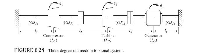
Find the flexibility and stiffness influence coefficients of the torsional system shown in Fig. 6.28. Also write the equations of motion of the system. (GJ)1 01 Compressor (GJ)2 (Jan) Turbine (142) (GJ)3 FIGURE 6.28 Three-degree-of-freedom torsional system. (GJ)4 Generator (43)
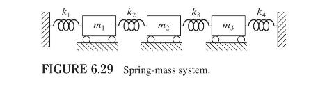
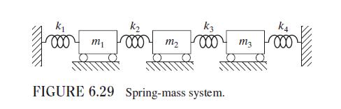
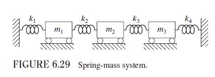
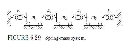
Find the flexibility and stiffness influence coefficients of the system shown in Fig. 6.29. Also, derive the equations of motion of the system. k1 k3 k4 000 /711 000 m2 000 my 000 FIGURE 6.29 Spring-mass system.
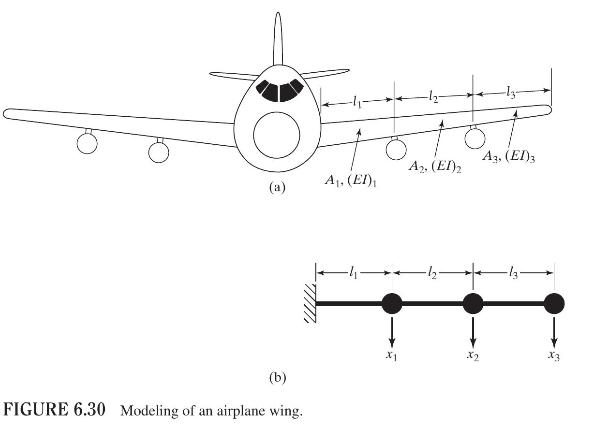
An airplane wing, Fig. 6.30(a), is modeled as a three-degree-of-freedom lumped-mass system, as shown in Fig. 6.30(b). Derive the flexibility matrix and the equations of motion of the wing by assuming that all \(A_{i}=A,(E I)_{i}=E I, l_{i}=l\) and that the root is fixed. A3, (EI)3 A2, (EI)2 (a) A,
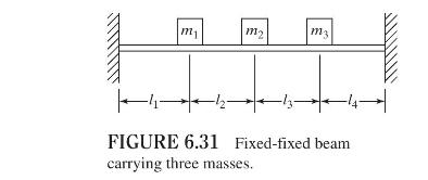
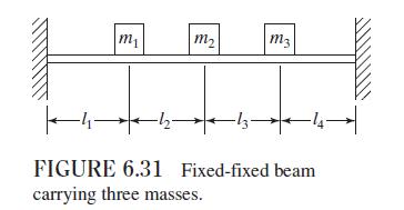
Determine the flexibility matrix of the uniform beam shown in Fig. 6.31. Disregard the mass of the beam compared to the concentrated masses placed on the beam and assume all \(l_{i}=l\). m m m3 FIGURE 6.31 Fixed-fixed beam carrying three masses. 47
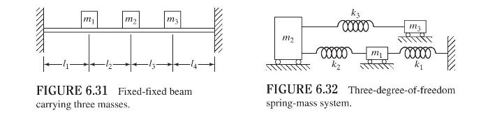
Derive the flexibility and stiffness matrices of the spring-mass system shown in Fig. 6.32 assuming that all the contacting surfaces are frictionless. m m2 m3 00000 m3 m2 00000 m1 k k FIGURE 6.31 Fixed-fixed beam carrying three masses. FIGURE 6.32 Three-degree-of-freedom spring-mass system.
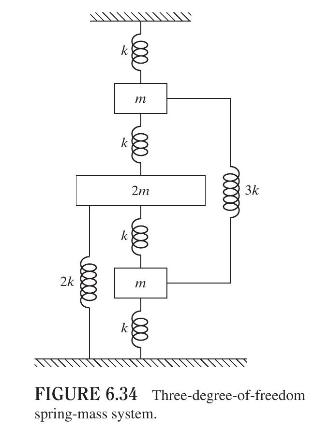
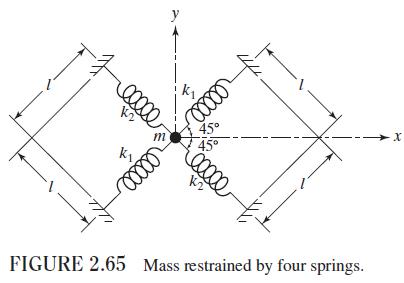
Derive the equations of motion of the system shown in Fig. 6.34. 000 m 00000 m 2m k 000000 2k 000 3k FIGURE 6.34 Three-degree-of-freedom spring-mass system.
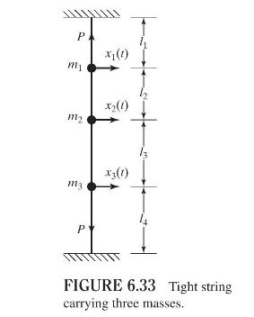
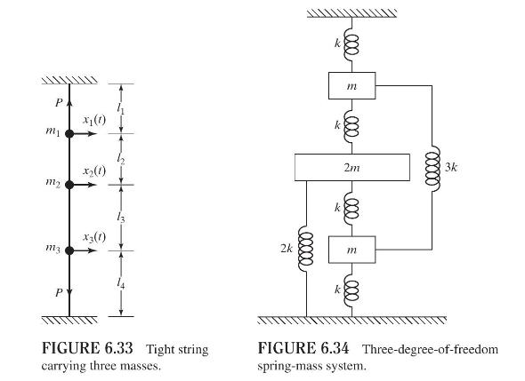
Derive the equations of motion for the tightly stretched string carrying three masses, as shown in Fig. 6.33. Assume the ends of the string to be fixed. P m1 m2 x1(1) X2(1) m3 X3(1) P FIGURE 6.33 Tight string carrying three masses.
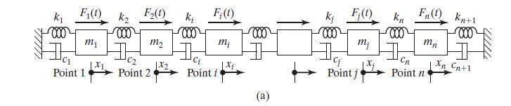
Four identical springs, each having a stiffness \(k\), are arranged symmetrically at \(90^{\circ}\) from each other, as shown in Fig. 2.65. Find the influence coefficient of the junction point in an arbitrary direction.Figure 2.65:- P mi x1 (1) m x2(1) m3 X3(1) P 2k 26 00000 000 m 2m m M -000 00000
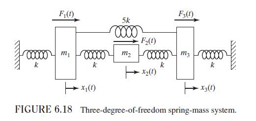
Show that the stiffness matrix of the spring-mass system shown in Fig. 6.3(a) is a band matrix along the diagonal.Figure 6.3(a):- F(t) F2(t) Fi(t) kj F(t) kn Fn(t) kn+1 000 000 000 000 000 000 m m m mj mn C Ci cj Cn 1x2 | Xi Xn Cn+1 Point 1 Point 2 Point i Point j Point n (a)
Derive the mass matrix of each of the systems shown in Figs. 6.18 using the indicated coordinates. F(1) 5k F2(t) 0.0 m 00000 m2 00000 k k F3(1) m3 00000 m 00000 k k -x(1) -x(1) -X3(1) FIGURE 6.18 Three-degree-of-freedom spring-mass system.
Derive the mass matrix of each of the systems shown in Figs. 6.19 using the indicated coordinates. 31 774 3k Freee 8(t) 2k C M,(t) Rigid bar, mass = 2m k 2m T x(1) F(t) m X(1) F2(t) FIGURE 6.19 Rigid bar connected to springs, masses and damper.
Derive the mass matrix of each of the systems shown in Figs. 6.20 using the indicated coordinates. R x(1) -21- 31- Rigid bar, mass = 2m A G k F(t) 5m X2(1) F(t) X3(1) F3(1) FIGURE 6.20 Three-degree-of-freedom damped system.
Derive the mass matrix of each of the systems shown in Figs. 6.21 using the indicated coordinates. k Pulley, mass M, mass moment of inertia Jo 2k 3r 3m T X1(1) F(t) T x2(1) m T X3(1) F2(t) 3k F3(t) FIGURE 6.21 Pulley attached to springs and masses.
Derive the mass matrix of each of the systems shown in Figs. 6.22 using the indicated coordinates. G3 G5 15 13 k2 04 Mcos wt 01 02 4 kn 12 G G4 16 G6 G Number of teeth on gear G = n, (i = 1 to 6) Mass moment of inertia of gear G = I, (i = 1 to 6) FIGURE 6.22 Three-degree-of-freedom gear train.
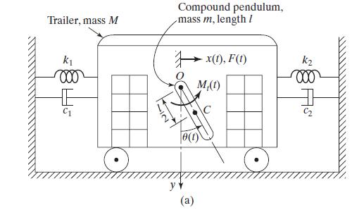
The inverse mass influence coefficient \(b_{i j}\) is defined as the velocity induced at point \(i\) due to a unit impulse applied at point \(j\). Using this definition, derive the inverse mass matrix of the system shown in Fig. 6.4(a).Figure 6.4(a):- Trailer, mass M Compound pendulum, mass m,
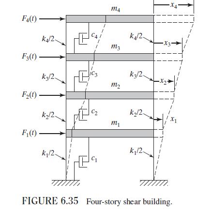
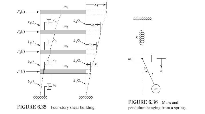
For the four-story shear building shown in Fig. 6.35, there is no rotation of the horizontal section at the level of floors. Assuming that the floors are rigid and the total mass is concentrated at the levels of the floors, derive the equations of motion of the building using(a) Newton's second law
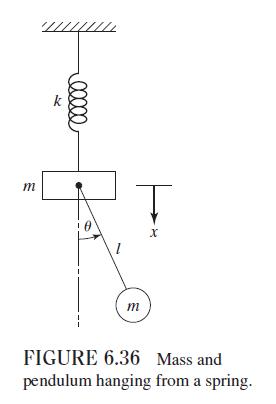
Derive the equations of motion of the system shown in Fig. 6.36 by using Lagrange's equations with \(x\) and \(\theta\) as generalized coordinates.Figure 6.36:- m k 00000 m T x FIGURE 6.36 Mass and pendulum hanging from a spring.
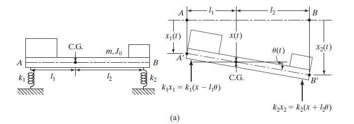
Derive the equations of motion of the system shown in Fig. 5.12(a), using Lagrange's equations with (a) \(x_{1}\) and \(x_{2}\) as generalized coordinates and (b) \(x\) and \(\theta\) as generalized coordinates.Figure 5.12(a):- A k C.G. m,Jo B 4 h 22 k2 T x(1) A' kx = k(x-40) (a) B x(t) e(t) X2(1)
Derive the equations of motion of the system shown in Fig. 6.29 using Lagrange's equations. k k k3 k4 000 m 000 m2 000 m3 000 FIGURE 6.29 Spring-mass system.
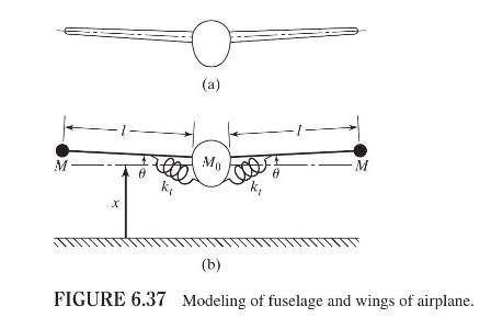
When an airplane (see Fig. 6.37(a)) undergoes symmetric vibrations, the fuselage can be idealized as a concentrated central mass \(M_{0}\) and the wings can be modeled as rigid bars carrying end masses \(M\), as shown in Fig. 6.37(b). The flexibility between the wings and the fuselage can be
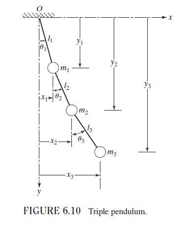
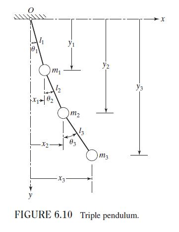
Derive the equations of motion of the triple pendulum shown in Fig. 6.10 using Lagrange's equations.Figure 6.10:- F(1) m4 F3(1) F(1) F(1) k/2 kz/2 k/2 k/2. m3 1112 m1 k/2 k/2 m 00000 m FIGURE 6.35 Four-story shear building. FIGURE 6.36 Mass and pendulum hanging from a spring.
Use Lagrange's equations to derive the equations of motion of each of the systems shown in Figs. 6.18. F(t) 5k F(1) F3(1) m m 00000 m 00000 k k k k x2(1) -x1 (1) X3(1) FIGURE 6.18 Three-degree-of-freedom spring-mass system.
Use Lagrange's equations to derive the equations of motion of each of the systems shown in Figs. 6.19. 7+ + CE 0(1) 2k 000 2m 3k Mt) Rigid bar, mass = 2m T x1(1) F(t) m x2(1) F2(t) FIGURE 6.19 Rigid bar connected to springs, masses and damper.
Use Lagrange's equations to derive the equations of motion of each of the systems shown in Figs. 6.20. 000 k Free -21- -31- Rigid bar, mass 2m A G T x(1) F(t) X3(1) F3(1) 5m x2(1) F(1) FIGURE 6.20 Three-degree-of-freedom damped system.
Use Lagrange's equations to derive the equations of motion of each of the systems shown in Figs. 6.21. Pulley, mass M, mass moment of inertia Jo 3r 2k 3m m T x1(1) F(t) I x2(1) 7 X3(1) F2(t) 3k F3(1) FIGURE 6.21 Pulley attached to springs and masses.
Use Lagrange's equations to derive the equations of motion of each of the systems shown in Figs. 6.22. G5 15 16 G3 G6 13 kp 03 14 02 G4 Mcos at 4 kn G 12 G Number of teeth on gear G = n, (i = 1 to 6) Mass moment of inertia of gear G = 1, (i = 1 to 6) FIGURE 6.22 Three-degree-of-freedom gear train.
Set up the eigenvalue problem of Example 6.11 in terms of the coordinates \(q_{1}=x_{1}, q_{2}=\) \(x_{2}-x_{1}\), and \(q_{3}=x_{3}-x_{2}\), and solve the resulting problem. Compare the results obtained with those of Example 6.11 and draw conclusions.Data From Example 6.11:-Figure 6.12:- Find the
Derive the frequency equation of the system shown in Fig. 6.29. k k k3 KA 000 m 000 m2 000 m3 000 FIGURE 6.29 Spring-mass system.
Find the natural frequencies and mode shapes of the system shown in Fig. 6.6 (a) when \(k_{1}=k, k_{2}=2 k, k_{3}=3 k, m_{1}=m, m_{2}=2 m\), and \(m_{3}=3 m\). Plot the mode shapes.Figure 6.6(a):- k 000 m x1 k m2 a x2 15 k3 m3
Set up the matrix equation of motion and determine the three principal modes of vibration for the system shown in Fig. 6.6(a) with \(k_{1}=3 k, k_{2}=k_{3}=k, m_{1}=3 m\), and \(m_{2}=m_{3}=m\). Check the orthogonality of the modes found.Figure 6.6(a):- k 000 m x1 k m2 a x2 15 k3 m3
Find the natural frequencies of the system shown in Fig. 6.10 with \(l_{1}=20 \mathrm{~cm}, l_{2}=30 \mathrm{~cm}\), \(l_{3}=40 \mathrm{~cm}, m_{1}=1 \mathrm{~kg}, m_{2}=2 \mathrm{~kg}\), and \(m_{3}=3 \mathrm{~kg}\).Figure 6.10:- 41 x102 m 2 m Y2 83 13 Om3 y FIGURE 6.10 Triple pendulum. x+
(a) Find the natural frequencies of the system shown in Fig. 6.31 with \(m_{1}=m_{2}=m_{3}=m\) and \(l_{1}=l_{2}=l_{3}=l_{4}=l / 4\).(b) Find the natural frequencies of the beam when \(m=10 \mathrm{~kg}, l=0.5 \mathrm{~m}\), the cross section is a solid circular section with diameter \(2.5
Determine the eigenvalues and eigenvectors of the system shown in Fig. 6.29, taking \(k_{1}=k_{2}=k_{3}=k_{4}=k\) and \(m_{1}=m_{2}=m_{3}=m\). k k k3 KA 000 m 000 mmy 000 FIGURE 6.29 Spring-mass system.
The frequency equation of a three-degree-of-freedom system is given by\[\left|\begin{array}{rrr}\lambda-5 & -3 & -2 \\-3 & \lambda-6 & -4 \\-1 & -2 & \lambda-6\end{array}\right|=0\]Find the roots of this equation.
Find the natural frequencies and principal modes of the triple pendulum shown in Fig. 6.10, assuming that \(l_{1}=l_{2}=l_{3}=l\) and \(m_{1}=m_{2}=m_{3}=m\). 4 m y2 102 m2 3 03 -x2 -X3- m3 FIGURE 6.10 Triple pendulum. x
Find the natural frequencies and mode shapes of the system shown in Fig. 6.29 for \(k_{1}=k_{2}=k_{3}=k_{4}=k, m_{1}=2 m, m_{2}=3 m\), and \(m_{3}=2 m\). k k k3 KA 000 m 000 mmy 000 FIGURE 6.29 Spring-mass system.
Showing 1200 - 1300
of 2655
First
6
7
8
9
10
11
12
13
14
15
16
17
18
19
20
Last
Step by Step Answers