

Question: Consider the block diagram of a feedback control system in Fig. 11.8, where K m = 1, G p = 1 / s + 1,
Figure 11.8
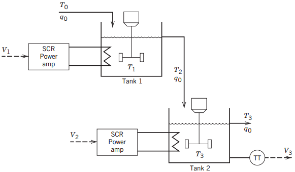
To 90 SCR V Power amp T1 T2 90 Tank 1 90 SCR V2 Power V3 TT ---> amp Tank 2
Step by Step Solution
★★★★★
3.52 Rating (165 Votes )
There are 3 Steps involved in it
1 Expert Approved Answer
Step: 1 Unlock

Substituting the transfer functions into ... View full answer
Question Has Been Solved by an Expert!
Get step-by-step solutions from verified subject matter experts
Step: 2 Unlock
Step: 3 Unlock
Document Format (2 attachments)
1602_606321ef17c94_680261.pdf
180 KBs PDF File
1602_606321ef17c94_680261.docx
120 KBs Word File