New Semester
Started
Get
50% OFF
Study Help!
--h --m --s
Claim Now
Question Answers
Textbooks
Find textbooks, questions and answers
Oops, something went wrong!
Change your search query and then try again
S
Books
FREE
Study Help
Expert Questions
Accounting
General Management
Mathematics
Finance
Organizational Behaviour
Law
Physics
Operating System
Management Leadership
Sociology
Programming
Marketing
Database
Computer Network
Economics
Textbooks Solutions
Accounting
Managerial Accounting
Management Leadership
Cost Accounting
Statistics
Business Law
Corporate Finance
Finance
Economics
Auditing
Tutors
Online Tutors
Find a Tutor
Hire a Tutor
Become a Tutor
AI Tutor
AI Study Planner
NEW
Sell Books
Search
Search
Sign In
Register
study help
engineering
materials science engineering
Fundamentals of Materials Science and Engineering An Integrated Approach 4th Edition David G. Rethwisch - Solutions
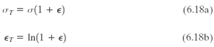
Show that Equations 6.18a and 6.18b are valid when there is no volume change during deformation.
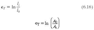
Demonstrate that Equation 6.16, the expression defining true strain, may also be represented by when specimen volume remains constant during deformation. Which of these two expressions is more valid during necking? Why?
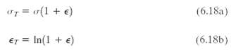
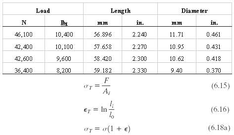
Using the data in Problem 6.28 and Equations 6.15, 6.16, and 6.18a, generate a true stress?true strain plot for aluminum. Equation 6.18a becomes invalid past the point at which necking begins; therefore, measured diameters are given below for the last four data points, which should be used in true
A tensile test is performed on a metal specimen, and it is found that a true plastic strain of 0.20 is produced when a true stress of 575MPa (83,500psi) is applied; for the same metal, the value of K in Equation 6.19 is 860MPa (125,000psi). Calculate the true strain that results from the
For some metal alloy, a true stress of 415MPa (60,175psi) produces a plastic true strain of 0.475. How much will a specimen of this material elongate when a true stress of 325MPa (46,125psi) is applied if the original length is 300 mm (11.8 in.)? Assume a value of 0.25 for the strain-hardening
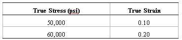
The following true stresses produce the corresponding true plastic strains for a brass alloy: What true stress is necessary to produce a true plastic strain of 0.25?
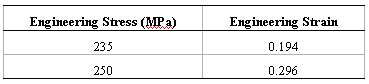
For a brass alloy, the following engineering stresses produce the corresponding plastic engineering strains, prior to necking: On the basis of this information, compute the engineering stress necessary to produce an engineering strain of 0.25.
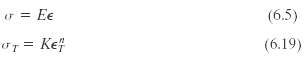
Find the toughness (or energy to cause fracture) for a metal that experiences both elastic and plastic deformation. Assume Equation 6.5 for elastic deformation, that the modulus of elasticity is 172GPa (25 ( 106psi), and that elastic deformation terminates at a strain of 0.01. For plastic
For a tensile test, it can be demonstrated that necking begins when Using Equation 6.19, determine the value of the true strain at this onset of necking.
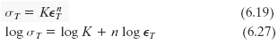
Taking the logarithm of both sides of Equation 6.19 yieldsThus, a plot of log σT versus log ∈T in the plastic region to the point of necking should yield a straight line having a slope of n and an intercept (at log σT = 0) of log K.Using the appropriate data tabulated in Problem 6.29, make
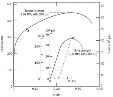
A cylindrical specimen of a brass alloy 7.5 mm (0.30 in.) in diameter and 90.0 mm (3.54 in.) long is pulled in tension with a force of 6000 N (1350lbf); the force is subsequently released. (a) Compute the final length of the specimen at this time. The tensile stress?strain behavior for this alloy
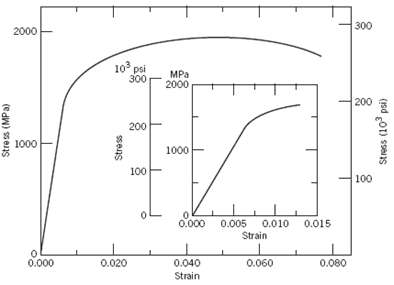
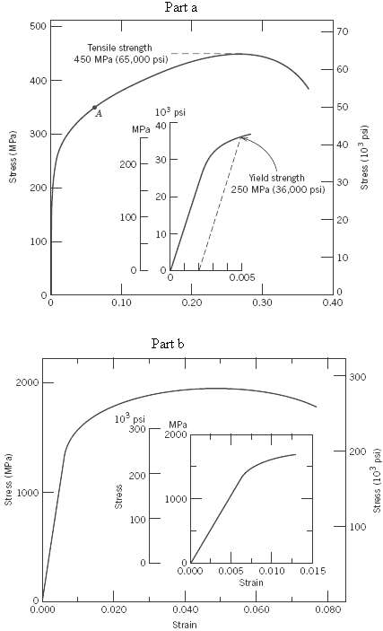
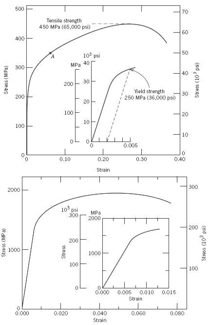
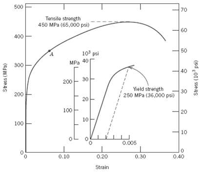
A steel alloy specimen having a rectangular cross section of dimensions 12.7 mm ? 6.4 mm (0.5 in. ? 0.25 in.) has the stress?strain behavior shown in figure. If this specimen is subjected to a tensile force of 38,000 N (8540lbf) then (a) Determine the elastic and plastic strain values. (b) If its
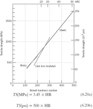
(a) A 10-mm-diameter Brinell hardness indenter produced an indentation 1.62 mm in diameter in a steel alloy when a load of 500 kg was used. Compute the HB of this material.(b) What will be the diameter of an indentation to yield a hardness of 450 HB when a 500 kg load is used?
Estimate the Brinell and Rockwell hardnesses for the following: (a) The naval brass for which the stress?strain behavior is shown in Figure 6.12. (b) The steel alloy for which the stress?strain behavior is shown in Figure 6.21.
Using the data represented in figure, specify equations relating tensile strength and Brinell hardness for brass and nodular cast iron, similar to Equations 6.20a and 6.20b for steels.
Cite five factors that lead to scatter in measured material properties.
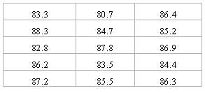
Below are tabulated a number of Rockwell B hardness values that were measured on a single steel specimen. Compute average and standard deviation hardness values
Upon what three criteria are factors of safety based?
Determine working stresses for the two alloys that have the stress?strain behaviors shown in Figures 6.12 and 6.21.
A large tower is to be supported by a series of steel wires. It is estimated that the load on each wire will be 11,100 N (2500lbf). Determine the minimum required wire diameter assuming a factor of safety of 2 and a yield strength of 1030MPa (150,000psi).
(a)?Gaseous hydrogen at a constant pressure of 1.013MPa (10atm) is to flow within the inside of a thin-walled cylindrical tube of nickel that has a radius of 0.1 m. The temperature of the tube is to be 300?C and the pressure of hydrogen outside of the tube will be maintained at 0.01013MPa (0.1atm).
Consider the steady-state diffusion of hydrogen through the walls of a cylindrical nickel tube as described in Problem 6.D2. One design calls for a diffusion flux of 5 × 10⁻⁸ mol/m2-s, a tube radius of 0.125 m, and inside and outside pressures of 2.026MPa (20atm) and 0.0203MPa (0.2atm),
To provide some perspective on the dimensions of atomic defects, consider a metal specimen that has a dislocation density of 104 mm-2. Suppose that all the dislocations in 1000 mm3 (1 cm3) were somehow removed and linked end to end. How far (in miles) would this chain extend? Now suppose
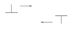
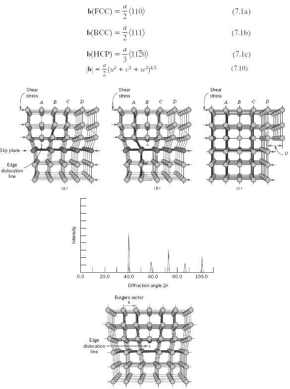
Consider two edge dislocations of opposite sign and having slip planes that are separated by several atomic distances as indicated in the diagram. Briefly describe the defect that results when these two dislocations become aligned with each other.
Is it possible for two screw dislocations of opposite sign to annihilate each other? Explain your answer.
For each of edge, screw, and mixed dislocations, cite the relationship between the direction of the applied shear stress and the direction of dislocation line motion.
(a) Define a slip system.(b) Do all metals have the same slip system? Why or why not?
(a) Compare planar densities (Section 3.11 and Problem 3.54) for the (100), (110), and (111) planes for FCC.(b) Compare planar densities (Problem 3.55) for the (100), (110), and (111) planes for BCC.
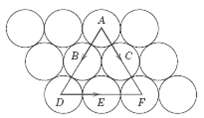
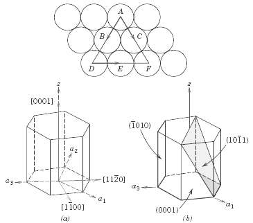
One slip system for the BCC crystal structure is {110}. In a manner similar to Figure, sketch a {110}-type plane for the BCC structure, representing atom positions with circles. Now, using arrows, indicate two different slip directions within this plane.
One slip system for the HCP crystal structure is {0001}. In a manner similar to Figure, sketch a {0001}-type plane for the HCP structure and, using arrows, indicate three different slip directions within this plane. You might find Figure helpful.
Equations 7.1a and 7.1b, expressions for Burgers vectors for FCC and BCC crystal structures, are of the form where a is the unit cell edge length. Also, since the magnitudes of these Burgers vectors may be determined from the following equation: determine values of |b| for aluminum and
(a) In the manner of Equations 7.1a, 7.1b, and 7.1c, specify the Burgers vector for the simple cubic crystal structure. Its unit cell is shown in Figure. Also, simple cubic is the crystal structure for the edge dislocation of Figure, and for its motion as presented in Figure. You may also want to
Sometimes cos ( cos ( in Equation 7.2 is termed the Schmid factor. Determine the magnitude of the Schmid factor for an FCC single crystal oriented with its [100] direction parallel to the loading axis.
Consider a metal single crystal oriented such that the normal to the slip plane and the slip direction are at angles of 43.1° and 47.9°, respectively, with the tensile axis. If the critical resolved shear stress is 20.7MPa (3000psi), will an applied stress of 45MPa (650psi) cause the single
A single crystal of aluminum is oriented for a tensile test such that its slip plane normal makes an angle of 28.1° with the tensile axis. Three possible slip directions make angles of 62.4°, 72.0°, and 81.1° with the same tensile axis.(a) Which of these three slip directions is most
Consider a single crystal of silver oriented such that a tensile stress is applied along a [001] direction. If slip occurs on a (111) plane and in a [101] direction, and is initiated at an applied tensile stress of 1.1MPa (160psi), compute the critical resolved shear stress.
A single crystal of a metal that has the FCC crystal structure is oriented such that a tensile stress is applied parallel to the [110] direction. If the critical resolved shear stress for this material is 1.75MPa, calculate the magnitude(s) of applied stress(es) necessary to cause slip to occur on
(a) A single crystal of a metal that has the BCC crystal structure is oriented such that a tensile stress is applied in the [010] direction. If the magnitude of this stress is 2.75MPa, compute the resolved shear stress in the [111] direction on each of the (110) and (101) planes.(b) On the basis of
Consider a single crystal of some hypothetical metal that has the FCC crystal structure and is oriented such that a tensile stress is applied along a [102] direction. If slip occurs on a (111) plane and in a [101] direction, compute the stress at which the crystal yields if its critical resolved
The critical resolved shear stress for iron is 27MPa (4000psi). Determine the maximum possible yield strength for a single crystal of Fe pulled in tension.
List four major differences between deformation by twinning and deformation by slip relative to mechanism, conditions of occurrence, and final result.
Briefly explain why small-angle grain boundaries are not as effective in interfering with the slip process as are high-angle grain boundaries.
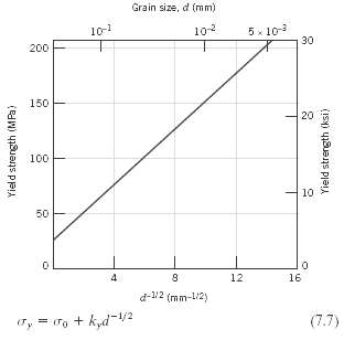
(a) From the plot of yield strength versus (grain diameter)?1/2 for a 70 Cu?30 Zn cartridge brass, Figure, determine values for the constants ?0 and ky in Equation 7.7. (b) Now predict the yield strength of this alloy when the average grain diameter is 1.0 x 10⁻³ mm.
The lower yield point for an iron that has an average grain diameter of 5 × 10⁻² mm is 135MPa (19,500psi). At a grain diameter of 8 × 10⁻³ mm, the yield point increases to 260MPa (37,500psi). At what grain diameter will the lower yield point be 205MPa (30,000psi)?
If it is assumed that the plot in figure is for noncold-worked brass, determine the grain size of the alloy in Figure 7.19; assume its composition is the same as the alloy in Figure 7.15.
In the manner of Figures 7.17b and 7.18b, indicate the location in the vicinity of an edge dislocation at which an interstitial impurity atom would be expected to be situated. Now briefly explain in terms of lattice strains why it would be situated at this position.
(a) Show, for a tensile test, that if there is no change in specimen volume during the deformation process (i.e., A0l0 = Adld). (b) Using the result of part (a), compute the percent cold work experienced by naval brass (the stress-strain behavior of which is shown in Figure 6.12) when a stress of
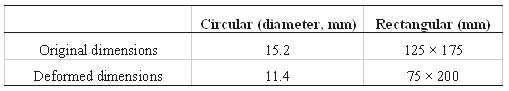
Two previously undeformed cylindrical specimens of an alloy are to be strain hardened by reducing their cross-sectional areas (while maintaining their circular cross sections). For one specimen, the initial and deformed radii are 16 mm and 11 mm, respectively. The second specimen, with an initial
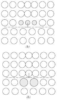
Two previously undeformed specimens of the same metal are to be plastically deformed by reducing their cross-sectional areas. One has a circular cross section, and the other is rectangular; during deformation the circular cross section is to remain circular, and the rectangular is to remain as
A cylindrical specimen of cold-worked copper has a ductility (%EL) of 25%. If its cold-worked radius is 10 mm (0.40 in.), what was its radius before deformation?
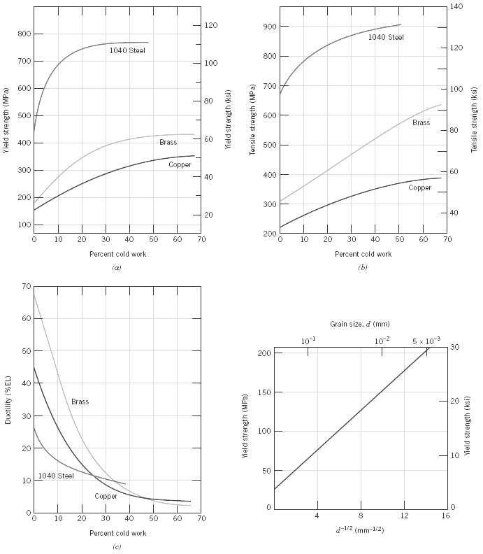
(a) What is the approximate ductility (%EL) of a brass that has a yield strength of 275MPa (40,000psi)?(b) What is the approximate Brinell hardness of a 1040 steel having a yield strength of 690MPa (100,000psi)?
Experimentally, it has been observed for single crystals of a number of metals that the critical resolved shear stress τcrss is a function of the dislocation density ρD aswhere τ0 and A are constants. For copper, the critical resolved shear stress is 2.10MPa (305psi) at a dislocation density of
Briefly cite the differences between recovery and recrystallization processes.
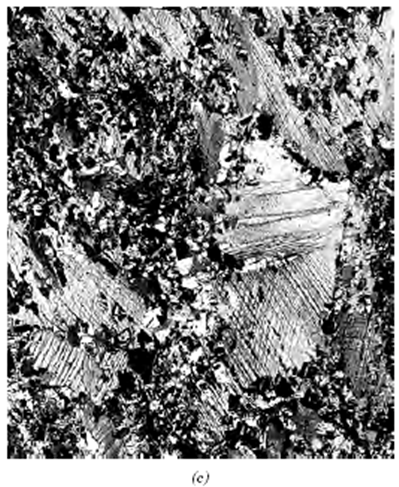
Estimate the fraction of recrystallization from the photomicrograph in Figure 7.21c.
Explain the differences in grain structure for a metal that has been cold worked and one that has been cold worked and then recrystallized.
(a) What is the driving force for recrystallization?(b) For grain growth?
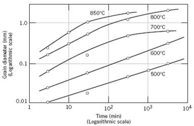
(a) From Figure, compute the length of time required for the average grain diameter to increase from 0.01 to 0.1 mm at 500?C for this brass material. (b) Repeat the calculation at 600?C.
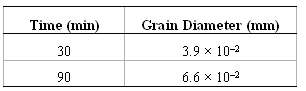
The average grain diameter for a brass material was measured as a function of time at 650?C, which is tabulated below at two different times: (a) What was the original grain diameter? (b) What grain diameter would you predict after 150 min at 650?C?
An undeformed specimen of some alloy has an average grain diameter of 0.040 mm. You are asked to reduce its average grain diameter to 0.010 mm. Is this possible? If so, explain the procedures you would use and name the processes involved. If it is not possible, explain why.
Grain growth is strongly dependent on temperature (i.e., rate of grain growth increases with increasing temperature), yet temperature is not explicitly given as a part of Equation 7.9.(a) Into which of the parameters in this expression would you expect temperature to be included?(b) On the basis of
An uncold-worked brass specimen of average grain size 0.008 mm has a yield strength of 160MPa (23,500psi). Estimate the yield strength of this alloy after it has been heated to 600°C for 1000 s, if it is known that the value of ky is 12.0 MPa-mm1/2 (1740 psi-mm1/2).
Determine whether or not it is possible to cold work steel so as to give a minimum Brinell hardness of 225, and at the same time have a ductility of at least 12%EL. Justify your decision.
Determine whether or not it is possible to cold work brass so as to give a minimum Brinell hardness of 120 and at the same time have a ductility of at least 20%EL. Justify your decision.
A cylindrical specimen of cold-worked steel has a Brinell hardness of 250.(a) Estimate its ductility in percent elongation.(b) If the specimen remained cylindrical during deformation and its original radius was 5 mm (0.20 in.), determine its radius after deformation.
It is necessary to select a metal alloy for an application that requires a yield strength of at least 345MPa (50,000psi) while maintaining a minimum ductility (%EL) of 20%. If the metal may be cold worked, decide which of the following are candidates: copper, brass, and a 1040 steel. Why?
A cylindrical rod of 1040 steel originally 15.2 mm (0.60 in.) in diameter is to be cold worked by drawing; the circular cross section will be maintained during deformation. A cold-worked tensile strength in excess of 840MPa (122,000psi) and a ductility of at least 12%EL are desired. Furthermore,
A cylindrical rod of copper originally 16.0 mm (0.625 in.) in diameter is to be cold worked by drawing; the circular cross section will be maintained during deformation. A cold-worked yield strength in excess of 250MPa (36,250psi) and a ductility of at least 12%EL are desired. Furthermore, the
A cylindrical 1040 steel rod having a minimum tensile strength of 865MPa (125,000psi), a ductility of at least 10%EL, and a final diameter of 6.0 mm (0.25 in.) is desired. Some 7.94 mm (0.313 in.) diameter 1040 steel stock, which has been cold worked 20% is available. Describe the procedure you
What is the magnitude of the maximum stress that exists at the tip of an internal crack having a radius of curvature of 2.5 × 10⁻⁴ mm (10-5 in.) and a crack length of 2.5 × 10⁻² mm (10-3 in.) when a tensile stress of 170MPa (25,000psi) is applied?
Estimate the theoretical fracture strength of a brittle material if it is known that fracture occurs by the propagation of an elliptically shaped surface crack of length 0.25 mm (0.01 in.) and having a tip radius of curvature of 1.2 ×10⁻³ mm (4.7 × 10⁻⁵ in.) when a stress of 1200MPa (174,000psi)
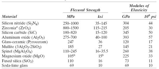
If the specific surface energy for soda-lime glass is 0.30 J/m2, using data contained in Table 12.5, compute the critical stress required for the propagation of a surface crack of length 0.05 mm.
A polystyrene component must not fail when a tensile stress of 1.25MPa (180psi) is applied. Determine the maximum allowable surface crack length if the surface energy of polystyrene is 0.50 J/m2 (2.86 × 10⁻³ in.-lbf/in.2). Assume a modulus of elasticity of 3.0GPa (0.435 × 10⁶psi).
A specimen of a 4340 steel alloy having a plane strain fracture toughness of 45MPα√m (41ksi√in) is exposed to a stress of 1000MPa (145,000psi). Will this specimen experience fracture if it is known that the largest surface crack is 0.75 mm (0.03 in.) long? Why or why not? Assume that the
Some aircraft component is fabricated from an aluminum alloy that has a plane strain fracture toughness of 35MPα√m (31.9 ksi√in). It has been determined that fracture results at a stress of 250MPa (36,250psi) when the maximum (or critical) internal crack length is 2.0 mm (0.08 in.). For this
Suppose that a wing component on an aircraft is fabricated from an aluminum alloy that has a plane strain fracture toughness of 40MPα√m (36.4ksi√in). It has been determined that fracture results at a stress of 365MPa (53,000psi) when the maximum internal crack length is 2.5 mm (0.10 in.). For
A large plate is fabricated from a steel alloy that has a plane strain fracture toughness of 55MPα√m (50ksi√in) If, during service use, the plate is exposed to a tensile stress of 200MPa (29,000psi), determine the minimum length of a surface crack that will lead to fracture. Assume a value of
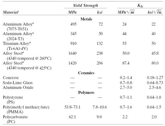
Calculate the maximum internal crack length allowable for a 7075-T651 aluminum alloy (Table 8.1) component that is loaded to a stress one half of its yield strength. Assume that the value of Y is 1.35.
A structural component in the form of a wide plate is to be fabricated from a steel alloy that has a plane strain fracture toughness of 77.0MPα√m (70.1ksi√in) and a yield strength of 1400MPa (205,000psi). The flaw size resolution limit of the flaw detection apparatus is 4.0 mm (0.16 in.). If
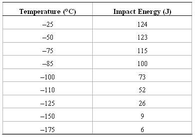
Following is tabulated data that were gathered from a series of Charpy impact tests on a ductile cast iron. (a) Plot the data as impact energy versus temperature. (b) Determine a ductile-to-brittle transition temperature as that temperature corresponding to the average of the maximum and minimum
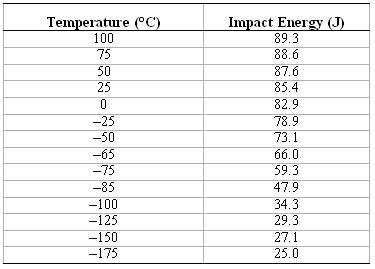
Following is tabulated data that were gathered from a series of Charpy impact tests on a tempered 4140 steel alloy. (a) Plot the data as impact energy versus temperature. (b) Determine a ductile-to-brittle transition temperature as that temperature corresponding to the average of the maximum and
A fatigue test was conducted in which the mean stress was 50MPa (7250psi) and the stress amplitude was 225MPa (32,625psi).(a) Compute the maximum and minimum stress levels.(b) Compute the stress ratio.(c) Compute the magnitude of the stress range.
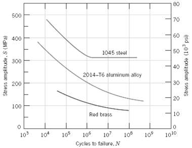
A cylindrical 1045 steel bar (Figure) is subjected to repeated compression-tension stress cycling along its axis.?If the load amplitude is 22,000 N (4950lbf), compute the minimum allowable bar diameter to ensure that fatigue failure will not occur. Assume a factor of safety of 2.0.
An 8.0 mm (0.31 in.) diameter cylindrical rod fabricated from a red brass alloy (Figure) is subjected to reversed tension-compression load cycling along its axis. If the maximum tensile and compressive loads are +7500 N (1700lbf) and -7500 N (-1700lbf), respectively, determine its fatigue life.
A 12.5 mm (0.50 in.) diameter cylindrical rod fabricated from a 2014-T6 alloy (Figure) is subjected to a repeated tension-compression load cycling along its axis. Compute the maximum and minimum loads that will be applied to yield a fatigue life of 1.0 ? 107 cycles. Assume that the stress plotted
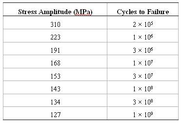
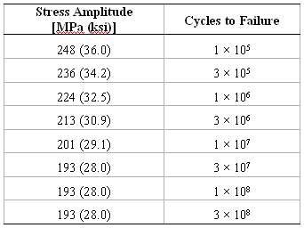
The fatigue data for a brass alloy are given as follows: (a) Make an S?N plot (stress amplitude versus logarithm cycles to failure) using these data. (b) Determine the fatigue strength at 5 ? 105 cycles. (c) Determine the fatigue life for 200MPa.
Suppose that the fatigue data for the brass alloy in Problem 8.18 were taken from torsional tests, and that a shaft of this alloy is to be used for a coupling that is attached to an electric motor operating at 1500 rpm. Give the maximum torsional stress amplitude possible for each of the following
The fatigue data for a ductile cast iron are given as follows: (a) Make an S?N plot (stress amplitude versus logarithm cycles to failure) using these data. (b) What is the fatigue limit for this alloy? (c) Determine fatigue lifetimes at stress amplitudes of 230MPa (33,500psi) and 175MPa
Suppose that the fatigue data for the cast iron in Problem 8.20 were taken for bending-rotating tests, and that a rod of this alloy is to be used for an automobile axle that rotates at an average rotational velocity of 750 revolutions per minute. Give maximum lifetimes of continuous driving that
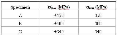
Three identical fatigue specimens (denoted A, B, and C) are fabricated from a nonferrous alloy. Each is subjected to one of the maximum-minimum stress cycles listed below; the frequency is the same for all three tests. (a) Rank the fatigue lifetimes of these three specimens from the longest to the
Cite five factors that may lead to scatter in fatigue life data.
Briefly explain the difference between fatigue striations and beachmarks both in terms of(a) Size and(b) Origin.
List four measures that may be taken to increase the resistance to fatigue of a metal alloy.
Give the approximate temperature at which creep deformation becomes an important consideration for each of the following metals: nickel, copper, iron, tungsten, lead, and aluminum.
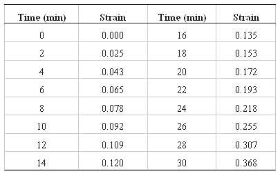
The following creep data were taken on an aluminum alloy at 400?C (750?F) and a constant stress of 25MPa (3660psi). Plot the data as strain versus time, then determine the steady-state or minimum creep rate.
A specimen 750 mm (30 in.) long of an S-590 alloy (Figure) is to be exposed to a tensile stress of 80MPa (11,600psi) at 815?C (1500?F). Determine its elongation after 5000 h. Assume that the total of both instantaneous and primary creep elongations is 1.5 mm (0.06 in.).
For a cylindrical S-590 alloy specimen (Figure) originally 10 mm (0.40 in.) in diameter and 500 mm (20 in.) long, what tensile load is necessary to produce a total elongation of 145 mm (5.7 in.) after 2,000 h at 730(C (1350(F)? Assume that the sum of instantaneous and primary creep elongations is
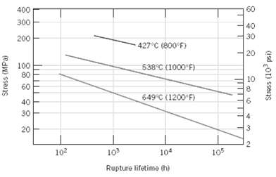
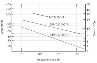
If a component fabricated from an s-590 alloy (figure 8.30) is to be exposed to a tensile stress of 300mpa (43,500psi) at 650(c (1200(f), estimate its rupture lifetime.
A cylindrical component constructed from an S-590 alloy (Figure) has a diameter of 12 mm (0.50 in.). Determine the maximum load that may be applied for it to survive 500 h at 925(C(1700(F).
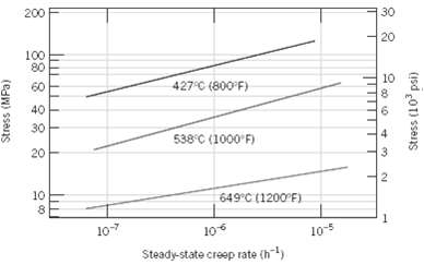
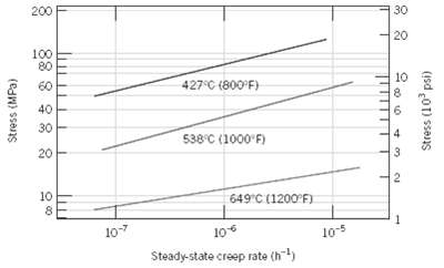
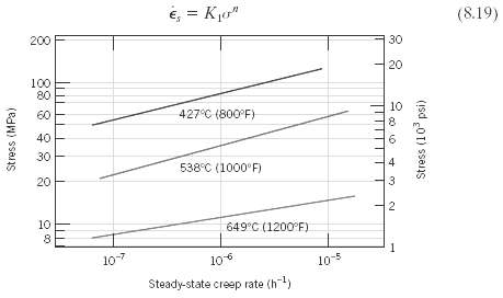
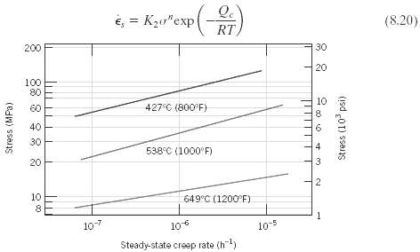
From Equation 8.19, if the logarithm of is plotted versus the logarithm of ?, then a straight line should result, the slope of which is the stress exponent n. Using Figure 8.31, determine the value of n for the S-590 alloy at 925?C, and for the initial (i.e., lower-temperature) straight line
(a) Estimate the activation energy for creep (i.e., Qc in Equation 8.20) for the S-590 alloy having the steady-state creep behavior shown in figure. Use data taken at a stress level of 300MPa (43,500psi) and temperatures of 650°C and 730°C. Assume that the stress exponent n is independent of
Showing 200 - 300
of 2249
1
2
3
4
5
6
7
8
9
10
11
12
13
14
15
Last
Step by Step Answers