New Semester
Started
Get
50% OFF
Study Help!
--h --m --s
Claim Now
Question Answers
Textbooks
Find textbooks, questions and answers
Oops, something went wrong!
Change your search query and then try again
S
Books
FREE
Study Help
Expert Questions
Accounting
General Management
Mathematics
Finance
Organizational Behaviour
Law
Physics
Operating System
Management Leadership
Sociology
Programming
Marketing
Database
Computer Network
Economics
Textbooks Solutions
Accounting
Managerial Accounting
Management Leadership
Cost Accounting
Statistics
Business Law
Corporate Finance
Finance
Economics
Auditing
Tutors
Online Tutors
Find a Tutor
Hire a Tutor
Become a Tutor
AI Tutor
AI Study Planner
NEW
Sell Books
Search
Search
Sign In
Register
study help
physics
electricity and magnetism
Physics 2nd edition Alan Giambattista, Betty Richardson, Robert Richardson - Solutions
Determine the potential difference φA €“ φB between points A and B of the circuit shown in Fig. 3.23. Under what condition is it equal to zero?
A capacitor of capacitance C1 = 1.0μF charged up to a voltage V = 110 V is connected in parallel to the terminals of a circuit consisting of two uncharged capacitors connected in series and possessing the capacitances C2 = 2.0μF and C3 = 3.0μF. What charge will flow through the
What charges will flow after the shorting of the switch Sw in the circuit illustrated in Fig. 3.24 through sections 1 and 2 in the directions indicated by the arrows?
In the circuit shown in Fig. 3.25 the emf of each battery is equal to ε = 60 V, and the capacitor capacitances are equal to C1 = 2.0μF and C2 = 3.0μF. Find the charges which will flow after the shorting of the switch Sw through section 1, 2 and 3 in the directions indicated by the
Find the potential difference φA €“ φB between points A and B of the circuit shown in Fig. 3.26.
Determine the potential at point 1 of the circuit shown in Fig. 3.27, assuming the potential at the point O to be equal to zero. Using the symmetry of the formula obtained, write the expressions for the potentials, at points 2 and 3.
Find the capacitance of the circuit shown in Fig. 3.28 between points A and B.
Determine the interaction energy of the point charges located at the corners of a square with the side a in the circuits shown in Fig. 3.29.
There is an infinite straight chain of alternating charges q and – q. The distance between the neighbouring charges is equal to a. Find the interaction energy of each charge with all the others. Make use of the expansion of in (l + a) in a power series in a
A point charge q is located at a distance l from an infinite conducting plane. Find the interaction energy 6f that charge with chose induced on the plane.
Calculate the interaction energy of two balls whose charges ql and q2 are spherically symmetrical. The distance between the centers of the balls is equal to l. Instruction. Start with finding the interaction energy of a ball and a thin spherical layer.
A capacitor of capacitance C1 = 1.0μF carrying initially a voltage V = 300 V is connected in parallel with an uncharged capacitor of capacitance C2: = 2.0μF. Find the increment of the electric energy of this system by the moment equilibrium is reached. Explain the result obtained.
What amount of heat will be generated in the circuit shown in Fig. 3.30 after the switch Sw is shifted from position I to position 2?
What amount of heat will be generated in the circuit shown in Fig. 3.31 after the switch Sw is shifted from position 1 to position 2?
A system consists of two thin concentric metal shells of radii R1 and R2 with corresponding charges ql and q2. Find the self-energy values W1 and W2 of each shell, the interaction energy of the shells W12, and the total electric energy of the system.
A charge q is distributed uniformly over the volume of a ball of radius R. Assuming the permittivity to be equal to unity, find: (a) The electrostatic self-energy of the ball; (b) The ratio of the energy W1 stored in the ball to the energy W pervading the surrounding space.
A point charge q = 3.0μC is located at the centre of a spherical layer of uniform isotropic dielectric with permittivity e = 3.0. The inside radius of the layer is equal to a = 250 ram, the outside radius is b – 500 ram. Find the electrostatic energy inside the dielectric layer.
A spherical shell of radius R1 with uniform charge q is expanded to a radius R21. Find the work performed by the electric forces in this process.
A spherical shell of radius R12 with a uniform charge q has a point charge q0 at its centre. Find the work performed by the electric forces during the shell expansion from radius R1 to radius R2.
A spherical shell is uniformly charged with the surface density σ, using the energy conservation law find the magnitude of the electric force acting on a unit area of the shell.
A point charge q is located at the centre O of a spherical uncharged conducting layer provided with a small orifice (Fig. 3.32). The inside and outside radii of the layer are equal to a and b respectively. What amount of work has to be performed to slowly transfer the charge q from the point O
Each plate of a parallel-plate air capacitor has an area S. What amount of work has to be performed to slowly increase the distance between the plates from xl to x2 if? (a) The capacitance of the capacitor, which is equal to q, or (b) The voltage across the capacitor, which is equal to V, is kept
Inside a parallel-plate capacitor there is a plate parallel to the outer plates, whose thickness is equal to η = 0.60 of the gap width. When the plate is absent the capacitor capacitance equals c – 20 nF. First, the capacitor was connected in parallel to a constant voltage source producing V
A parallel-plate capacitor was lowered into water in a horizontal position, with water filling up the gap between the plates d = t.0 mm wide. Then a constant voltage V = 500 V was applied to the capacitor. Find the water pressure increment in the gap.
A parallel-plate capacitor is located horizontally so that one of its plates is submerged into liquid while the other is over its surface (Fig. 3.33). The permittivity of the liquid is equal to e, its density is equal to p. To what height will the level of the liquid in the capacitor rise after its
A cylindrical layer of dielectric with permittivity e is inserted into a cylindrical capacitor to fill up all the space between the electrodes. The mean radius of the electrode a equals R, the gap between them is equal to d, with d
A capacitor consists of two stationary plates shaped as a semi-circle of radius R and a movable plate made of dielectric with permittivity e and capable of rotating about an axis O between the stationary plates (Fig. 3.34). The thickness of the movable plate is equal to d which is practically the
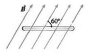
A flat, rectangular coil consisting of 50 turns measures 25.0 cm by 30.0 cm. It is in a uniform, 1.20-T, magnetic field, with the plane of the coil parallel to the field. In 0.222 s, it is rotated so that the plane of the coil is perpendicular to the field. (a) What is the change in the magnetic
In a physics laboratory experiment, a coil with 200 turns enclosing an area of 12 cm2 is rotated in 0.040 s from a position where its plane is perpendicular to the earth's magnetic field to a position where its plane is parallel to the field. The earth's magnetic field at the lab location is 6.0 X
In a physics laboratory experiment, a coil with 200 turns enclosing an area of 12 cm2 is rotated in 0.040 s from a position where its plane is perpendicular to the earth's magnetic field to a position where its plane is parallel to the field. The earth's magnetic field at the lab location is 6.0 X
A closely wound search coil (Exercise 29.3) has an area of 3.20 cm2, 120 turns, and a resistance of 60.0 Ω. It is connected to a charge-measuring instrument whose resistance is 45.0 Ω. When the coil is rotated quickly from a position parallel to a uniform magnetic field to a position
A circular loop of wire with a radius of 12.0 cm and oriented in the horizontal xy-plane is located in a region of uniform magnetic field. A field of 1.5 T is directed along the positive z-direction, which is upward. (a) If the loop is removed from the field region in a time interval of 2.0 ms,
A coil 4.00 cm in radius, containing 500 turns, is placed in a uniform magnetic field that varies with time according to B = (0.0120 T/s)t + (3.00 x 10⁻⁵ T/s4)t4. The coil is connected to a 600-0 resistor, and its plane is perpendicular to the magnetic field. You can ignore the resistance of the
A coil 4.00 cm in radius, containing 500 turns, is placed in a uniform magnetic field that varies with time according to B = (0.0120 T/s)t + (3.00 x 10⁻⁵ T/s4)t4. The coil is connected to a 600-0 resistor, and its plane is perpendicular to the magnetic field. You can ignore the resistance of the
A flat, circular, steel loop of radius 75 cm is at rest in a uniform magnetic field, as shown in an edge-on view in Fig. 29.28. The field is changing with time, according to B (t) = (1.4T)e -(0?057 B-1)t.(a) Find the emf induced in the loop as a function of time.(b) When is the induced emf equal to
Shrinking Loop A circular loop of flexible iron wire has an initial circumference of 165.0 cm, but its circumference is decreasing at a constant rate of 12.0 cm/s due to a tangential pull on the wire. The loop is in a constant, uniform magnetic field oriented perpendicular to the plane of the loop
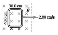
A rectangle measuring 30.0 cm by 40.0 cm is located inside a region of a spatially uniform magnetic field of 1.25 T, with the field perpendicular to the plane of the coil (Fig. 29.29). The coil is pulled out at a steady rate of 2.00 cm/s traveling perpendicular to the field lines. The region of the
In a region of space, a magnetic field points in the + x-direction (toward the right). Its magnitude varies with position according to the formula Bx = B0 + bx, where Bo and b are positive constants, for x > 0. A flat coil of area A moves with uniform speed v from right to left with the plane of
A motor with a brush-and-commutators arrangement, as described in Example 29.5 has a circular coil with radius 2.5 cm and 150 turns of wire. The magnetic field has magnitude 0.060 T, and the coil rotates at 440rev/min(a) What is the maximum emf induced in the coil? (b) What is the average back emf?
The armature of a small generator consists of a flat, square coil with 120 turns and sides with a length of 1.60 cm. The coil rotates in a magnetic field of 0.0750 T. What is the angular speed of the coil if the maximum emf produced is 24.0 m V?
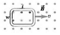
A flat, rectangular coil of dimensions l and w is pulled with uniform speed v through a uniform magnetic field B with the plane of its area perpendicular to the field (Fig. 29.30).(a) Find the emf induced in this coil(b) If the speed and magnetic field are both tripled, what is the inducedemf?
A circular loop of wire is in a region of spatially uniform magnetic field, as shown in Fig. 29.31. The magnetic field is directed into the plane of the figure. Determine the direction (clockwise or counterclockwise) of the induced current in the loop when(a) B is increasing;(b) B is decreasing;(c)
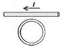
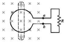
The current in Fig. 29.32 obeys the equation I(t) = I0e??bt, where b > O. Find the direction (clockwise or counterclockwise) of the current induced in the round coil fort >O.
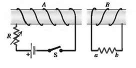
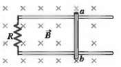
Using Lenz's law, determine the direction of the current in resistor ab of Fig. 29.33 when(a) Switch S is opened after having been closed for several minutes;(b) Coil B is brought closer to coil A with the switch closed;(c) The resistance of R is decreased while the switch remainsclosed.
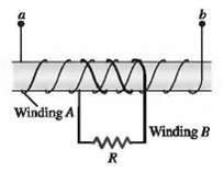
A cardboard tube is wrapped with two windings of a insulated wire wound in opposite directions, as shown in Fig. 29.34. Terminals a and b of winding A may be connected to a battery through a reversing switch. State whether the induced current in the resistor R is from left to right R or from right
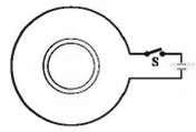
A sma1l, circular ring is inside a larger loop that is connected to a battery and a switch, as shown in Fig. 29.35. Use Lenz's law to find the direction of the current induced in the small ring(a) Just after switch S is closed;(b) After S has been closed a long time;(c) Just after S has been
A 1.50-m-Iong metal bar is pulled to the right at a steady 5.0 m/s perpendicular to a uniform, 0.750-T magnetic field. The bar rides on parallel metal rails connected through a 25.0-n resistor, as shown in Fig. 29.36, so the apparatus makes a complete circuit. You can ignore the resistance of the
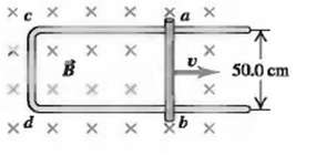
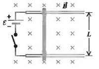
In Fig. 29.37 a conducting rod of length L = 30.0 cm moves in a magnetic field B of magnitude 0.450 T directed into the plane of the figure. The rod moves with speed v = 5.00 m/s in the direction shown. (a) What is the potential difference between the ends of the rod? (b) Which point a to b, is at
For the situation in Exercise 29.20, find (a) The motional emf in the bar and (b) The current through the resistor.
Are Motional emfs a Practical Source of Electricity? How fast (in m/s and mph) would a 5.00-cm copper bar have to move at right angles to a 0.650-T magnetic field to generate 1.50 V (the same as a AA battery) across its ends? Does this seem like a practical way to generate electricity?
Motional emfs in Transportation Airplanes and trains move through the earth's magnetic field at rather high speeds, so it is reasonable to wonder whether this field can have a substantial effect on them. We shall use a typical value of 0.50 G for the earth's field (a) The French TGV train and the
The conducting rod ab shown in Fig. 29.38 makes contact with metal rails ca and db. The apparatus is in a uniform magnetic field of 0.800 T, perpendicular to the plane of the figure(a) Find the magnitude of the emf induced in the rod when it is moving toward the right with a speed 7.50 m/s.(b) In
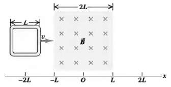
A square loop of wire with side length L and resistance R is moved at constant speed v across a uniform magnetic field confined to a square region whose sides are twice the length of those of the square loop (Fig. 29.39).(a) Graph the external force F needed to move the loop at constant speed as a
A1.41-m bar moves through a uniform, 1.20-T magnetic field with a speed of 2.50 m/s (Fig. 29.40). In each case, find the emf induced between the ends of this bar and identify which, if any, end (a or b) is at the higher potential. The bar moves in the direction of(a) The + x-axis;(b) The ??
A long, thin solenoid has 900 turns per meter and radius 250 cm. The current in the solenoid is increasing at a uniform rate of 60.0 A/s. What is the magnitude of the induced electric field at a point near the center of the solenoid and (a) 0.500 cm from the axis of the solenoid; (b) 1.00 cm from
The magnetic field within a long, straight solenoid with a circular cross section and radius R is increasing at a rate of dB/dt.(a) What is the rate of change of flux through a circle with radius r1 inside the solenoid, normal to the axis of the solenoid, and with center on the solenoid axis? (b)
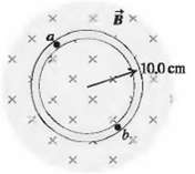
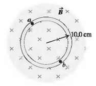
The magnetic field B at all points within the colored circle shown in Fig. 29.31 has an initial magnitude of 0.750 T. (The circle could represent approximately the space inside a long, thin solenoid.) The magnetic field is directed into the plane of the diagram and is decreasing at the rate of
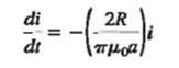
A long, thin solenoid has 400 turns per meter and radius 1.10 cm. The current in the solenoid is increasing at a uniform rate di/dt. The induced electric field at a point near the center of the solenoid and 3.50 cm from its axis is 8.00 X l0-6 V /m. Calculate di/dt.
A metal ring 4.50 cm in diameter is placed between the north and south poles of large magnets with the plane of its area perpendicular to the magnetic field. These magnets produce an initial uniform field of 1.12 T between them but are gradually pulled apart, causing this field to remain uniform
A long, straight solenoid with a cross-sectional area of 8.00 cm2 is wound with 90 turns of wire per centimeter, and the windings carry a current of 0.350 A. A second winding of 12 turns encircles the solenoid at its center. The current in the solenoid is turned off such that the magnetic field of
A dielectric of permittivity 3.5 x l0-l1 F/m completely fills the volume between two capacitor plates. For t > 0 the electric flux through the dielectric is {8.0 x 10³ V· m/s3) t3. The dielectric is ideal and nonmagnetic; the conduction current in the dielectric is zero. At what time does the
The electric flux through a certain area of a dielectric is (8.76 x l03 V · m/s4)t4. The displacement current through that area is 12.9 pA at time t = 26.1 ms. Calculate the dielectric constant for the dielectric.
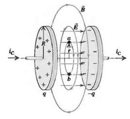
A parallel-plate, air-filled capacitor is being charged as in Fig. 29.23. The circular plates have radius 4.00 cm, and at a particular instant the conduction current in the wires is 0.280 A. (a) What is the displacement current density jD in the air space between the plates? (b) What is the rate at
Displacement Current in a Dielectric Suppose that the parallel plates in Fig. 29.23 have an area of 3.00 cm2 and are separated by a 2.50-mm-thick sheet of dielectric that completely fills the volume between the plates, the dielectric has dielectric constant 4.70. (You can ignore fringing effects.)
In Fig. 29.23 the capacitor plates have area 5.00 cm2 and separation 2.00 mm. The plates are in vacuum. The charging current ic has a constant value of 1.80mA. At t = 0 the charge on the plates is zero.(a) Calculate the charge on the plates, the electric field between the plates, and the potential
Displacement Current in a Wire A long, straight, copper wire with a circular cross-sectional area of 2.1 mm2 carries a current of16 A. The resistivity of the material is 2.0 X 10⁻⁸Ω ∙ m. (a) What is the uniform electric field in the material? (b) If the current is changing at the
A long, straight wire made of a type-I superconductor carries a constant current I along its length. Show that the current cannot be uniformly spread over the wire's cross section but instead must all be at the surface.
A type-II superconductor in an external field between Be1 and Bc2 has regions that contain magnetic flux and have resistance, and also has superconducting regions. What is the resistance of a long, thin cylinder of such material?
At temperatures near absolute zero, Bc approaches 0.142 T for vanadium, a type-I superconductor. The normal phase of vanadium has a magnetic susceptibility close to zero. Consider a long, thin vanadium cylinder with its axis parallel to an external magnetic field B0 m the + x-direction. At points
The compound SiV3, is a type-II superconductor At temperatures near absolute zero the two critical fields are Be1 = 55.0 mT and Bc2 = 15.0 T. The normal phase of SiV3 has a magnetic susceptibility close to zero. A long, thin SiV3 cylinder has its axis parallel to an external magnetic field Bo in
A Changing Magnetic Field you are testing a new data acquisition system. This system allows you to record a graph of the current in a circuit as a function of time. As part of the test, you are using a circuit made up of a 4.00-cm-radius, 500-turn coil of copper wire connected in series to a 600-0
(a) Find the current in the large circuit 200?s after S is closed.(c) Find the direction of the current in the small circuit.(d) Justify why we can ignore the magnetic field from all the wires of the large circuit except for the wire closest to the smallcircuit.
A flat coil is oriented with the plane of its area at right angles to a spatially uniform magnetic field. The magnitude of this field varies with time according to the graph in Fig. 29.42. Sketch a qualitative (but accurate!) graph of the emf induced in the coil as a function of time. Be sure to
A circular wire loop of radius a and resistance R initially bas a magnetic flux through it due to an external magnetic field. The external field then decreases to zero. A current is induced in the loop while the external field is changing; however this current does not stop at the instant that the
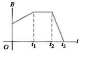
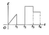
A coil is stationary in a spatially uniform, external, time-varying magnetic field. The emf induced in this coil as a function of time is shown if Fig. 29.43. Sketch a clear qualitative graph of the external magnetic field as a function of time given that it started from zero. Include the point t1,
In Fig. 29.44 the loop is being pulled to the right at constant speed v. A constant current I flows in the long wire in the direction shown.(a) Calculate the magnitude of the net emf ? induced in the loop. Do these two ways: (i) by using Faraday's law of induction and (ii) by looking at the emf
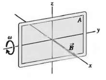
Suppose the loop in Fig. 29.45 is(a) Rotated about the y-axis;(b) Rotated about the x-axis;(c) Rotated about an edge parallel to the z-axis. What is the maximum induced emf in each case if A = 600 cm2, w = 35.0 rad/s, and B = 0.450T?
As a new electrical engineer for the local power company, you are assigned the project of designing a generator of sinusoidal ac voltage with a maximum voltage of 120 V. Besides plenty of wire, you have two strong magnets that can produce a constant uniform magnetic field of 1.5 T over a square
Make a Generator? You are shipwrecked on a deserted tropical island. You have some electrical devices that you could operate using a generator but you have no magnets. The earth's magnetic field at your location is horizontal and has magnitude 8.0 X 10⁻⁵ T, and you decide to try to use this field
A flexible circular loop 6.50 cm in diameter lies in a magnetic field with magnitude 0.950 T, directed into the plane of the page as shown in Fig. 29.46. The loop is pulled at the points indicated by the arrows, forming a loop of zero area in 0.250 s.(a) Find the average induced emf in the
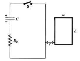
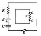
A Circuit within a Circuit Fig. 29.47 shows a small circuit within a larger one, both lying on the surface of a table. The switch is closed at t = 0 with the capacitor initially uncharged. Assume that the small circuit has no appreciable effect on the larger one.(a) What is the direction (a to b or
Terminal Speed A conducting rod with length L, mass m, and resistance R moves without friction on metal rails. A uniform magnetic field B is directed into the plane of the figure. The rod starts from rest and is acted on by a constant force F directed to the right. The rails are infinitely long and
Terminal Speed A bar of length L = 0.8 m is free to slide without friction on horizontal rails, as shown in Fig. 29.48. There is a uniform magnetic field B = 1.5 T directed into the plane of the figure. At one end of the rails there is a battery with emf ? = 12 V and a switch. The bar has mass 0.90
Antenna emf A satellite, orbiting the earth at the equator at an altitude of 400 km. has an antenna that can be modeled as a 2.0-m-long rod. The antenna is oriented perpendicular to the earth's surface. At the equator, the earth's magnetic field is essentially horizontal and has a value of 8.0 X
At the equator, the earth's magnetic field is approximately horizontal, is directed toward the north, and has a value of 8 X 10⁻⁵ T. (a) Estimate the emf induced between the top and bottom of a bullet shot horizontally at a target on the equator if the bullet is shot toward the east. Assume the
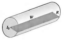
A very long, cylindrical wire of radius R carries a current 10 uniformly distributed across the cross section of the wire. Calculate the magnetic flux through a rectangle that has one side of length W running down the center of the wire and another side of length R, as shown in Fig. 29.49 (see
(c) Because of the internal resistance of the ring, the current through R at the time given in part (b) is only 3.00mA. Determine the internal resistance of the ring. (d) Determine the emf in the ring at a time t = 1.21 X 10⁻² s. What is the polarity of the emf? (e) Determine the time at which the
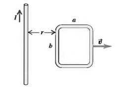
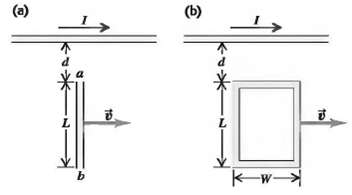
The long, straight wire shown in Fig. 29.51a carries constant current 1. A metal bar with length L is moving at constant velocity V, as shown in the figure. Point a is a distance d from the wire.(a) Calculate the emf induced in the bar.(b) Which point, a or b, is at higher potential?(c) If the bar
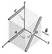
The cube shown in Fig. 29.52, 50.0 cm on a side, is in a uniform magnetic field of 0.120 T, directed along the positive y-axis. Wires A, C, and D move in the directions indicated, each with a speed of 0.350 m/s. (Wire A moves parallel to the xy-plane, C moves at an angle of 45.0" below the
A slender rod, 0.240 m long, rotates with an angular speed of 8.80 rad/s about an axis through one end and perpendicular to the rod. The plane of rotation of the rod is perpendicular to a uniform magnetic field with a magnitude of 0.650 T. (a) What is the induced emf in the rod? (b) What is the
A Magnetic Exercise Machine you have designed a new type of exercise machine with an extremely simple mechanism (Fig. 29.36). A vertical bar of silver (chosen for its low resistivity and because it makes the machine look cool) with length L = 3.0 m is free to move left or right without friction on
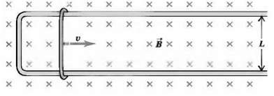
A rectangular loop with width L and a slide wire with mass m are as shown in Fig. 29.53. A uniform magnetic field B is directed perpendicular to the plane of the loop into the plane of the figure. The slide wire is given an initial speed of Vo and then released. There is no friction between the
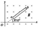
A 25.0-cm-long metal rod lies in the xy-plane and makes an angle of 36.90 with the positive x-axis and an angle of 53.10 with the positive y-axis. The rod is moving in the + x- direction with a speed of 4.20mfs. The rod is in a uniform magnetic field B = (0.120T) i (0.220 T)j - (0.0900 T)k. (a)
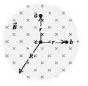
The magnetic field B, at all points within a circular region of radius R, is uniform in space and directed into the plane of the page as shown in Fig. 29.54. (The region could be a cross section inside the windings of a long, straight solenoid.) If the magnetic field is increasing at a rate dB/dt,
An airplane propeller of total length L rotates around its center with angular speed '" in a magnetic field that is perpendicular to the plane of rotation Modeling the propeller as a thin, uniform bar, find the potential difference between (a) The center and either end of the propeller and (b) The
It is impossible to have a uniform electric field that abruptly drops to zero in a region of space in which the magnetic field is constant and in which there are no electric charges. To prove this statement, use the method of contradiction: Assume that such a case is possible and then show that
Falling Square Loop A vertically oriented, square loop of copper wire falls from a region where the field B is horizontal, uniform, and perpendicular to 1he plane of 1he loop, into a region where 1he field is zero. The loop is released from rest and initially is entirely within the magnetic-field
In a region of space where there are no conduction or displacement currents. it is impossible to have a uniform magnetic field that abruptly drops to zero. To prove this statement, use the method of contradiction: Assume that such a case is possible, and then show 1hat your assumption contradicts a
A capacitor has two parallel plates with area A separated by a distance d. The space between plates is filled with a material having dielectric constant K. The material is not a perfect insulator but has resistivity p. The capacitor is initially charged with charge of magnitude Qo on each plate
(b) Assuming E = EO, find the maximum displacement current density in the wire, and compare with 1he result of part (a). (c) At what frequency f would the maximum conduction and displacement densities become equal if E = EO (which is not actually the case)? (d) At the frequency determined in part
Showing 2900 - 3000
of 8940
First
23
24
25
26
27
28
29
30
31
32
33
34
35
36
37
Last
Step by Step Answers
.PNG)
.PNG)
.PNG)
.PNG)
.PNG)
.PNG)
.PNG)
.PNG)
.PNG)
.PNG)
.PNG)
.PNG)