New Semester
Started
Get
50% OFF
Study Help!
--h --m --s
Claim Now
Question Answers
Textbooks
Find textbooks, questions and answers
Oops, something went wrong!
Change your search query and then try again
S
Books
FREE
Study Help
Expert Questions
Accounting
General Management
Mathematics
Finance
Organizational Behaviour
Law
Physics
Operating System
Management Leadership
Sociology
Programming
Marketing
Database
Computer Network
Economics
Textbooks Solutions
Accounting
Managerial Accounting
Management Leadership
Cost Accounting
Statistics
Business Law
Corporate Finance
Finance
Economics
Auditing
Tutors
Online Tutors
Find a Tutor
Hire a Tutor
Become a Tutor
AI Tutor
AI Study Planner
NEW
Sell Books
Search
Search
Sign In
Register
study help
physics
mechanics
An Introduction to Geotechnical Engineering 2nd edition Robert D. Holtz, William D. Kovacs, Thomas C. Sheahan - Solutions
The liquid limit of a soil is 68. Estimate the value of the modified secondary compression index.
For the soil and loading conditions of Examples 9.1 and 9.2, estimate how long it would take for 0.2, 0.35, and 0.45 m of settlement to occur. Consider both single and double drainage.?
By evaluation of the series expression [Eq. (B.2.23) in Appendix B.2] for the solution to the consolidation equation, determine the average degree of consolidation U to the nearest 0.001 for time factors 0.15, 0.6, 0.8 and infinity. Verify your computations by referring to Table 9.1 and Fig.
How much difference would there be in the(a) Computed ultimate settlement(b) The time required for 90% consolidation for the soil conditions of Example 9.7 if the clay layer were doubly drained?
A deposit of Swedish clay is 11 m thick, on the average, and apparently drained on the bottom. The coefficient of consolidation for the clay was estimated to be 1.7 x 10⁻⁴ cm2/s from laboratory tests. A settlement analysis based on consolidation tests predicted an ultimate consolidation settlement
A conventional laboratory consolidation test on a 25 mm thick sample gave a time for 90% consolidation equal to 9.5 min. Compute cv in cm2/s, m2/s, and ft2/d.
A conventional laboratory consolidation test on a 25 mm thick sample gave a time for 90% consolidation equal to 9.5 min. Calculate cv in cm2/s, m2/s, and ft2/d. Discuss.
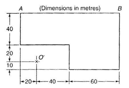
Given the data of Example 10.6. Instead of a load on the surface, compute the depth of an excavation to cause a reduction in stress at the bottom of the excavation of 200 kPa if ρ = 2.1 Mg/m3. The excavation plan area is shown in Fig. Ex. 10.6a.?
For the excavation of Problem 10.10, estimate the stress change at a depth of 50 m below the bottom of the excavation at point O'.qo = -200 kPa, z = 50 mDetermine the stress decrease using Fig. 10.4 (or Eq. 10.6) for the vertical stress under the corner of a uniformly loaded rectangular area. Use
A strip footing 2.5 m wide is loaded on the ground surface with a pressure equal to 175 kPa. Calculate the stress distribution at depths of 2.5, 7.5 and 12.5 m under the center of the footing. If the footing rested on a normally consolidated cohesive layer whose LL was 78 and whose PL was 47,
A large oil storage tank 90 m in diameter is to be constructed on the soil profile shown in Fig. P10.16. Average depth of the oil in the tank is 18 m, and the specific gravity of the oil is 0.92. Consolidation tests from the clay layer are similar to those given in Problem 8.18. Estimate the
Estimate the ultimate consolidation settlement under the centerline of a 17 x 17 m mat foundation. The mat is 1.2 m thick reinforced concrete, and the average stress on the surface of the slab is 80 kPa. The soil profile is shown in Fig. P10.17. Oedometer tests on samples of the clay provide these
Three uniformly distributed loads of 100 kPa each are applied to 10 x 10 m square areas on the soil profile shown in Fig. P10.18. Undisturbed samples of the clay were taken prior to construction, and consolidation tests indicated that the average preconsolidation stress is about 110 kPa, the
A series of oil storage tanks are to be constructed near Mystic River power station in Boston, MA. The typical tank is 22 m in diameter, and it exerts an average foundation stress of about 125 kPa. The soil profile at the site is very similar to that shown in Fig. 8.19 (a), see next page. Estimate
If you used the Boussinesq (or Westergaard) theory for Problem 10.1, do the problem again but use the Westergaard (or Boussinesq) theory instead. Comment on the differences between the two theories.?
A new highway to Siracha, Thailand, is to be constructed east of Bangkok, across a region of deep deposits of very soft marine clay. A typical soil profile is shown in Fig. 8.21(a). The average Cc = 0.8 below the drying crust. The proposed embankment is 17 m wide at the top, has three horizontal to
Figure P10.21 shows a proposed foundation site, with 10 ft of sand overlying 15 ft of clay with consolidation properties shown. The clay is normally consolidated. Assume 1-D conditions.(a) Compute the initial σ’v at the middle of the clay layer prior to excavation and construction.(b) After
As part of a construction project, a 7.5 m thick layer of clay is to be loaded with a temporary 3 m thick sand layer. The figure below shows the water table location, soil unit weights, and the compression curve properties for the clay. Assume the sand layer remains dry.(a) Calculate the value of
The figure shows the 1-D compression curve for a clay.(a) Using log interpolation between 100 and 1000, determine the σ’v value at a vertical strain, σ’v = 20%.(b) If the initial void ratio, eo = 0.846, determine Cr and Cc for this soil. For Cc, use the portion of the curve between σ’v =
A large embankment is to be built on the surface of a 15-ft clay layer. Before the embankment is built, the initial σ'v at the middle of the clay layer is 480 psf. The results from a 1-D consolidation test on the clay from the middle of the layer are as follows: σ'p = 1800 psf, C rε = 0.0352, C
The figure shows a proposed site where an excavation will be made. The 10 ft layer of sand will be removed, so that the top of the 24 ft. normally consolidated clay layer will be exposed. Assume full capillarity in the clay only.(a) Assume that the water table location remains the same during
The figure shows the soil profile at a site where you plan to lower the water table. You have results from two consolidation tests, one from the upper 12 ft thick over-consolidated crust, and another from the lower 32 ft thick normally consolidated zone. You plan to lower the water table from its
When a consolidation test is performed on some soils, the virgin compression region is not linear, but bilinear. The figure shows such a compression curve from a 15 ft thick layer.(a) What vertical strain, εv, occurs when the soil is loaded from an initial σ’v1 = 560 psf to σ’v2 = 3000
The figure shows a soil profile where a clay layer will consolidate under an embankment loading of 150 kPa. There is no capillarity. Your firm performed two consolidation tests: i) one test indicated that the soil is over-consolidated, with σ’p = 110 kPa. ii) one test indicated that the
Compute the data and draw a curve of σ z/Q versus depth for points directly below a point load Q. On the same plot draw curves of σ z/Q versus depth for points directly below the center of square footings with breadths of 6.5 m and 20 m, respectively, each carrying a uniformly distributed load Q.
The center of a rectangular area at ground surface has Cartesian coordinates (0, 0), and the corners have coordinates (7, 18). All dimensions are in meters. The area carries a uniform pressure of 150 kPa. Estimate the stresses at a depth of 20 m below ground surface at each of the following
Compare the results of Problem 10.4 with those of the 2:1 method. Comments?
Calculate the stress distribution with depth at a point 3.5 m from the corner (along the longest side) of a rectangular loaded area 15 by 35 m with a uniform load of 75 kPa.qo = 75 kPa and z varies Determine the stress increase using Fig. 10.4 (or Eq. 10.6) for the vertical stress under the corner
How far apart must two 18 m diameter tanks be placed such that their stress overlap is not greater than 10% of the contact stress at depths of 10, 20, and 30 m?
Work Example 10.5, using superposition of the results of Figs. 10.7 and 10.4. How does your answer compare with the solution for Example 10.5?
Given an element with stresses as indicated in the figure, find:(a) The major and minor principal stresses and the planes on which they act.(b) The stresses on a plane inclined at 30° from the horizontal.(c) The max, shear stress and the inclination of the plane on which it acts.?
Given the element with stresses as shown in the figure:(a) Find the magnitude and direction of σH and σH.(b) Find the magnitude and direction of σ1 and σ3.?
Given the data of Example 11.5(a) Find the magnitude of the stresses on the horizontal plane.(b) Find the maximum shear stress, and determine the angle between the plane on which it acts and the major principal plane.
The state of stress on a small element is σ v = 21 kPa, σ h = 10 kPa, and the shear stress on the horizontal plane is +3 kPa. (a) Find the magnitude and directions of the major and minor principal stresses. (b) If the material is a loose sand, can you say whether the element is in a state of
Given the vertical and horizontal normal stresses of Problem 11.12 Find the maximum values of shear stress on the horizontal and vertical planes to cause failure in a medium dense sand. Assume the angle of internal friction for the sand is 32°.?
The state plane stress in a mass of dense cohesionless sand is described by the following stresses:Normal stress on horizontal plane = 296 kPaNormal stress on vertical plane = 160 kPaShear stress on horizontal and vertical planes = +/- 64 KPaDetermine by means of the Mohr circle the magnitude and
At a given point within a sand deposit the major, intermediate, and minor principal stresses are 10, 6, and 4 Mn/m2, respectively. Construct the Mohr diagram, and from it scale the normal and shearing stresses and the obliquity angles on planes at 35°, 50°, 65°, and 80° from the major principal
A 1-m cube within a mass of stressed soil has a stress of 200 kPa on its top and bottom faces, 100 kPa on one pair of vertical faces, and 60 kPa on the other pair of vertical faces. There is no shear stress on any face. Fill in the following table. (After Taylor, 1948.)?
In Problem 11.16 what is σ, assuming c = 0?
a) Draw the Mohr circle for this point, showing the pole location. (b) What are the stresses acting on a horizontal plane passing through this point? (c) The cohesion intercept for this soil is and the friction angle is if the major principal stress remains the same, what would the minor principal
Work Problem 11.1 with the element rotated 30° clockwise from the horizontal.
The figure shows an element of soil at the interface between two dry sand layers on a 28° slope. The interface is 10 ft below the ground surface, and for both sand layers the friction angle is 34° and Ko = 0.44. Assume that the shear stress is zero on both the vertical and horizontal
In a direct shear test on a specimen of cohesionless sand, the vertical normal stress on the specimen is 240 kN/m= and the horizontal shear stress at failure is 160 kN/m2.Assuming uniform stress distribution within the failure zone and a straight line failure envelope which goes through the origin,
A specimen of sand is tested in direct simple shear. The stress conditions are shown. Initial conditions: σ v = 3.12 kg/cm2, Ko = 0.5 At failure: σ v = 3.12 kg/cm=, t hv = 1.80 kg/cm2(a) Draw the Mohr circles for both initial and final stress conditions.(b) Show clearly the locations of the poles
Two conventional CD triaxial compression tests were conducted on a dense angular dry sand at the same void ratio. Test A had a confining pressure of 150 kPa, while in test B the confining pressure was 600 kPa; these stresses were held constant throughout the test. At failure, tests A and B had
Two consolidated-drained triaxial tests were performed on specimens of the same clay, with the following results at failure:Test 1: σ'1 = 73.4 psi, σ'3 = 26.6 psiTest 2: σ'1 = 48.0 psi, σ'3 = 12.0 psiDetermine the effective Mohr-Coulomb failure envelope (∅' and c) based on these test results.
With the element of Problem 11.1 rotated 40° clockwise from the horizontal, find the magnitude and direction of the stresses on the vertical plane.
A triaxial specimen of loose sand is first consolidated non-hydrostatically, with σ1 = 15 kPa and σ 3 = 10 kPa. The sample is then failed by holding the vertical stress constant and decreasing the horizontal stress (this is a lateral extension test). The angle of internal friction is 30° (c =
Another sample of the same sand tested in Problem 11.30 (consolidated non-hydrostatically, with σ1 = 15 kPa and σ 3 = 10 kPa) is tested by holding the vertical stress constant and increasing the horizontal stress (this is a lateral compression test). The angle of internal friction is 30° (c =
Work Example 11.3 with the element rotated 30° clockwise from the horizontal. In addition, find the stresses (magnitude and direction) on the horizontal plane.
The state of plane stress in a body is described by the following stresses: σ1 = 8500 kN/m2 compression, σ3 = 1500 kN/m2 tension. Determine by means of the Mohr circle the normal stress and shear stress on a plane inclined at 20° to the plane on which the minor principal stress acts. Check the
At a certain critical point in a steel beam, on a vertical plane the compressive stress is 115 MPa and the shearing stress is 31.5 MPa. There is no normal stress on the longitudinal (horizontal) plane. Find the stresses acting on the principal planes and the orientation of principal planes with the
A soil sample is under a biaxial state of stress. On plane 1, the stresses are (13, 4), while on plane 2, the stresses are (5.8, -2). Find the major and minor principal stresses
For the element shown in the figure:(a) Find the magnitude of the unknown stresses σh and σh on the horizontal plane.(b) Find the orientation of the principal stresses; clearly indicate their orientation in a small sketch.(c) Show the orientation of the planes of maximum as well as minimum
A granular material is observed being dumped from a conveyor belt. It forms a conical pile with about the same slope angle, 1.8 horizontal to 1 vertical. What is the angle of internal friction of this material?
Indicate the orientations of the major principal stress, the minor principal stress, and the failure plane of the tests in Problems 12.8 and 12.9.
A granular soil is tested in direct shear under a normal stress of 350 kPa. The size of the specimen is 7.62 cm in diameter. If the soil to be tested is a dense sand with an angle of internal friction of 38°, determine the size of the force transducer required to measure the shear force with a
The stresses induced by a surface load on a loose horizontal sand layer were found to be v = 5.13 kPa, t v = 1.47 kPa, t h = 3.2 kPa, t h = -1.47 kPa. By means of Mohr circles, determine if such a state of stress is safe. Use Eq. (11.11) for the definition of factor of safety.?
If the same stress conditions as in Problem 12.12 act on a very dense gravelly sand, is such a state safe against failure?
The effective normal stresses acting on the horizontal and vertical planes in a silty gravel soil are 1.77 MPa and 2.95 MPa, respectively. The shear stress on these planes is ±0.59 MPa. For these conditions, what are the magnitude and direction of the principal stresses? Is this a state of failure?
A specimen of dense sand tested in a triaxial CD test failed along a well-defined failure plane at an angle of 62° with the horizontal. Find the effective confining pressure of the test if the principal stress difference at failure was 115 kPa.
A dry loose sand is tested in a vacuum triaxial test in which the pore air pressure of the specimen is lowered below gage pressure to within about 95% of -1 atm. Estimate the principal stress difference and the major principal stress ratio at failure.?
For the data shown in Fig. 12.5(a), what is(a) The principal stress difference(b) The principal stress ratio at an axial strain of 12% for an effective confining pressure of 1.3 MPa?
For the conditions given in Problem 12.17, plot the Mohr circle.?
Do Problems 12.17 and 12.18 for the data shown in Fig. 12.6(a). Use σ c = 1.0 MPa.?
A drained trixial test is performed on al sand with σʹ 3c = σʹ 3f = 450 kPa. At failure, t max = 594 kPa. Find σʹ 1f, (σ1 - σ3)f, and ∅ʹ.?
Assume the sand of Problem 12.22 is Sacramento River sand at a void ratio of 0.6. If the initial volume of the specimen was 62 cm3, what change in volume would you expect during shear?
A silty sand is tested consolidated-drained in a triaxial cell where both principal stresses at the start of the test were 625 kPa. If the total axial stress at failure is 2.04 MPa while the horizontal pressure remains constant, compute the angle of shearing resistance and the theoretical
A specimen of sand failed when (σ1 - σ3) was 750 kPa. If the hydrostatic consolidation stress was 250 kPa, compute the angle of shearing resistance of the sand. What else can you say about the sand?
A specimen of sand at the field density is known to have a (σ1/ σ3) max of 3.8. If such a specimen is hydrostatically consolidated to 1180 kPa in a triaxial test apparatus, at what effective confining pressure will the specimen fail if the vertical stress is held constant? (This is a lateral
Two CD triaxial tests are conducted on identical specimens of the same sand. Both specimens are initially consolidated hydrostatically to 50 kPa; then each specimen is loaded as shown. Specimen A failed when the applied ∆σ1 was 180 kPa. Make the necessary calculations to(a) Plot the Mohr
Plot a graph of σʹ 1 / σʹ 3 versus ∅ʹ.?
Estimate the shear strength parameters of a fine (beach) sand (SP). Estimate the minimum and maximum void ratios?
A sub-rounded to sub-angular sand has a D10 of about 0.1 mm and a uniformity coefficient of 3. The angle of shearing resistance measured in the direct shear test was 47°. Is this reasonable? Why or why not?
Estimate the ∅' values for(a) A well-graded sandy gravel (GW) at a density of 1.9 Mg/m3.(b) A poorly graded silty sand with a field density of 1.70 Mg/m3.(c) An SW material at 100% relative density.(d) A poorly graded gravel with an in situ void ratio of 0.5.?
The results of a series of CD triaxial tests on a medium dense, cohesionless sand are summarized in the table below. The void ratios for all the test specimens were approximately the same at the start of the test. Plot the strength circles and draw the Mohr failure envelope for this series of
Estimate the values of the coefficient of earth pressure at rest, Ko, for the four soils of Problem 12-31.
If the sands of Problem 12.33 had been preloaded, would your estimate of be any different? If so, would it be higher or lower? Why?
Estimate Ko for sands 1, 4, 5, 6, 8, and 10 in Table 12.1 for relative densities of 40% and 85%.
A CD axial compression triaxial test on a normally consolidated clay failed along a clearly defined failure plane of 54°. The cell pressure during the test was 220 kPa. Estimate ∅', the maximum principal stress ratio and the principal stress difference at failure.
An unconfined compression test is performed on a dense silt. Previous drained triaxial tests on similar samples of the silt gave ∅' = 32o. If the unconfined compressive strength was 420 kPa, estimate the height of capillary rise in this soil above the ground water table. (Hint: Find the effective
A direct shear test was conducted on a fairly dense sample of Franklin Falls sand from New Hampshire. The initial void ratio was 0.668. The shear box was 76 mm square, and initially the height of the specimen was 11 mm. The tabulated data were collected during shear. Compute the data needed and
The results of unconfined compression tests on a sample of clay in both the undisturbed and remolded states are summarized below. Determine the compressive strength, the initial tangent modulus of deformation, and the secant modulus of deformation at 50% of the compressive strength for both the
For the data shown in Fig. 8.5, estimate the unconfined compressive strength and the sensitivity of this soil. Typical values for the clay are LL = 88, PL = 43, and PI = 45.?
A conventional triaxial compression test was conducted on a sample of dense sand fromFt. Peck Dam, Montana. The initial area of the test specimen was 10 cm2 and its initial height was 70 mm. Initial void ratio was 0.605. The following data were observed during shear. First, calculate the average
The results of two CD triaxial tests at different confining pressures on medium dense, cohesionless sand are summarized in the table below. The void ratios of both specimens were approximately the same at the start of the test. Plot on one set of axes the principal stress difference versus axial
For the two tests of Problem 12.6, determine the angle of internal friction of the sand at(a) Peak compressive strength(b) At ultimate compressive strength(c) At 5.5% axial strain.
A sand is hydrostatically consolidated in a triaxial test apparatus to 450 kPa and then sheared with the drainage valves open. At failure, (σ1 - σ3) is 1121 kPa. Determine the major and minor principal stresses at failure and the angle of shearing resistance. Plot the Mohr diagram. (This problem
The same sand as in Problem 12.8 is tested in a direct shear apparatus under a normal pressure of 390 kPa. The specimen fails when a shear stress of 260 kPa is reached. Determine the major and minor principal stresses at failure and the angle of shearing resistance. Plot the Mohr diagram.
Evaluate the and for the conditions shown in Fig. 13.6.?
The test of Problem 12.22 is conducted un-drained. An un-drained triaxial test is performed on a sand with σ'3c = σ'3f = 450 kPa. At failure, t max = 594 kPa. Find (σ 1 - σ 3)f, ∅', ∅ total, and the angle of the failure plane in the specimen. ∆uf = 100 kPa.?
If the test of Problem 13.12 were conducted at an initial confining pressure of 1000 kPa, estimate the principal stress difference and the induced pore water pressure at failure.
A silty sand is tested consolidated-drained in a triaxial cell where both principal stresses at the start of the test were 500 kPa. If the total axial stress at failure is 1.63 MPa while the horizontal pressure remains constant, compute the angle of shearing resistance and the theoretical
If the consolidation pressure in the CU test of Problem 13.14 were 1000 kPa instead of 500 kPa, estimate the pore pressure at failure.?
If the sample of Problem 13.15 was sheared un-drained and the induced pore pressure at failure was 200 kPa, estimate the principal stress difference at failure. What would be the angle of shearing resistance in terms of total stresses?
The data presented in Fig. 8.20(b) are for a black fissured organic silty clay or clayey silt. At a depth of 6 m, estimate the expected value or range of values of the un-drained modulus.?
The initial stress conditions in a soil sample are σ v = 10 MPa and σ h = 5 MPa, draw stress paths for σ v being held constant while (a) σ h increases to 10 MPa (b) σ h decreases to 0.?
The medium gray silty clay of Fig. 8.23(b) at a depth of 20 m had an LL of 38 and a PL of 23. Estimate the following parameters for this soil:(a) Coefficient of earth pressure at rest;(b) Effective angle of internal friction;(c) Ratio of t f / σ'vo;(d) Activity;(e) Sensitivity;(f) The un-drained
Suppose an identical specimen of the same clay as in Problem 12.38 was sheared un-drained, and the induced pore pressure at failure was 85 kPa. Determine the principal stress difference, total and effective principal stress ratios, ∅', ∅ total, A f, and α f for this test.?
A series of drained direct shear tests were performed on a saturated clay. The results, when plotted on a Mohr diagram, gave c' = 10 kPa and tan ∅' = 0.5. Another specimen of this clay was consolidated to an effective pressure of 100 kPa. An un-drained direct shear test was performed, and the
Showing 21700 - 21800
of 21795
First
204
205
206
207
208
209
210
211
212
213
214
215
216
217
218
Step by Step Answers
.png)
.png)
.png)
.png)
.png)
.png)
.png)
.png)
.png)
.png)
.png)
.png)
.png)
.png)
.png)
.png)
.png)
.png)
.png)
.png)
.png)
.png)
.png)
.png)
.png)
.png)
.png)
.png)
.png)

