

Question: Objective To implement a Verilog gate level model for ripple carry adder subtractor. Outcome Gate level implementation for the following components. FULL _ ADDER HALF
Objective
To implement a Verilog gate level model for ripple carry adder subtractor.
Outcome
Gate level implementation for the following components.
FULLADDER
HALFADDER
RCADDSUB
Instruction
Continue with your Modelsim Project as in Lab Assignment
Complete gate level description of following components
HALFADDER module in halfadder.v
FULLADDER module in fulladder.v
RCADDSUB module in rcaddsubv
Compile entire Project and simulate following testbenches in ModelSim simulator.
HALFADDERTB
FULLADDERTB
RCADDSUBTB
Observe result on waveform windows and fix any issue.
This will also generate following output files.
OUTPUThalfadder.out
OUTPUTfulladder.out
OUTPUTrcaddsubout
This should match with given golden file in CSProjectGOLDEN
halfadder.out.golden
fulladder.out.golden
rcaddsubout.golden
Add more testing in testbenches to make sure outcome is correct.
Name: fulladder.v
Module: FULLADDER
Output: S : Sum
CO : Carry Out
Input: A : Bit
B : Bit
CI : Carry In
Notes: bit full adder implementaiton.
include prjdefinition.v
module FULLADDERSCOAB CI;
output SCO;
input AB CI;
TBD
Endmodule;
Name: halfadder.v
Module: HALFADDER
Output: Y : Sum
C : Carry
Input: A : Bit
B : Bit
Notes: bit half adder implementaiton.
include prjdefinition.v
module HALFADDERY CAB;
output YC;
input AB;
TBD
Endmodule;
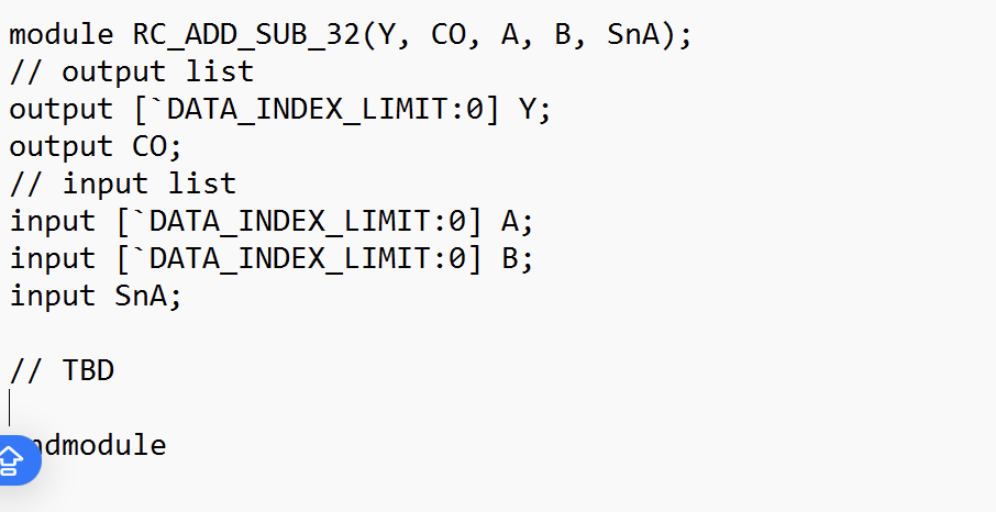
Name: rcaddsubv
Module: RCADDSUB
Output: Y : Output bit
CO : Carry Out
Input: A : bit input
B : bit input
SnA : if SnA it is add, subtraction otherwise
Notes: bit adder subtractor implementaiton.
include prjdefinition.v
module RCADDSUBY CO A B SnA;
output list
output : Y;
output CO;
input list
input : A;
input : B;
input SnA;
TBD
endmodule
module RCADDSUBY CO A B SnA;
output list
output DATAINDEXLIMIT: Y;
output CO;
input list
input DATAINDEXLIMIT: A;
input DATAINDEXLIMIT: B;
input SnA;
TBD
endmodule
Step by Step Solution
There are 3 Steps involved in it
1 Expert Approved Answer
Step: 1 Unlock

Question Has Been Solved by an Expert!
Get step-by-step solutions from verified subject matter experts
Step: 2 Unlock
Step: 3 Unlock