New Semester
Started
Get
50% OFF
Study Help!
--h --m --s
Claim Now
Question Answers
Textbooks
Find textbooks, questions and answers
Oops, something went wrong!
Change your search query and then try again
S
Books
FREE
Study Help
Expert Questions
Accounting
General Management
Mathematics
Finance
Organizational Behaviour
Law
Physics
Operating System
Management Leadership
Sociology
Programming
Marketing
Database
Computer Network
Economics
Textbooks Solutions
Accounting
Managerial Accounting
Management Leadership
Cost Accounting
Statistics
Business Law
Corporate Finance
Finance
Economics
Auditing
Tutors
Online Tutors
Find a Tutor
Hire a Tutor
Become a Tutor
AI Tutor
AI Study Planner
NEW
Sell Books
Search
Search
Sign In
Register
study help
engineering
mechanical engineering
Vector Mechanics For Engineers Statics And Dynamics 8th Edition Ferdinand Beer, E. Russell Johnston, Jr., Elliot Eisenberg, William Clausen, David Mazurek, Phillip Cornwell - Solutions
Using Mohr’s circle, determine for the area indicated the orientation of the principal centroidal axes and the corresponding values of the moments of inertia. Area of Problem 9.77
The moments and product of inertia for an L102 × 76 × 6.4-mm angle cross section with respect to two rectangular axes x and y through C are, respectively, Ix =0.166 × 106 mm4, Iy =0.453 × 106 mm4, and Ixy < 0, with the minimum value of the moment of inertia of the area with respect to any
Using Mohr’s circle, determine for the cross section of the rolled-steel angle shown the orientation of the principal centroidal axes and the corresponding values of the moments of inertia. (Properties of the cross sections are given in Fig. 9.13.)
Using Mohr’s circle, determine for the cross section of the rolled-steel angle shown the orientation of the principal centroidal axes and the corresponding values of the moments of inertia. (Properties of the cross sections are given in Fig. 9.13.)
For a given area the moments of inertia with respect to two rectangular centroidal x and y axes are Ix = 640 in4 and Iy = 280 in4, respectively. Knowing that after rotating the x and y axes about the centroid 60° clockwise the product of inertia relative to the rotated axes is −180 in4, use
It is known that for a given n area Iy = 300 in4 and Ixy = −125 in4, where the x and y axes are rectangular centroidal axes. If the axis corresponding to the maximum product of inertia is obtained by rotating the x axis 67.5o counterclockwise about C, use Mohr’s circle to determine(a) The
Using Mohr’s circle, show that for any regular polygon (such as a pentagon)(a) The moment of inertia with respect to every axis through the centroid is the same,(b) The product of inertia with respect to every pair of rectangular axes through the centroid is zero.
Using Mohr’s circle, prove that the expression Ix′ Iy′ −Ix′ y′ is independent of the orientation of the x′ and y′ axes, where Ix′, Iy′, and Ix′ y′ represent the moments and product of inertia, respectively, of a given area with respect to a pair of rectangular axes x′ and
Using the invariance property established in the preceding problem, express the product of inertia a Ixy of an area A with respect to a pair of rectangular axes through O in terms of the moments of inertia Ix and Iy of A and the principal moments of inertia I min and Imax of A about O. Use the
The quarter ring shown has a mass m and was cut from a thin, uniform plate. Knowing that r1 = ½ r2, determine the mass moment of inertia of the quarter ring with respect to (a) Axis AA′, (b) The centroidal axis CC′ that is perpendicular to the plane of the quarter ring.
A thin, semielliptical plate has a mass m. Determine the mass moment of inertia of the plate with respect to(a) The centroidal axis BB′,(b) The centroidal axis CC′ that is perpendicular to the plate.
The elliptical ring shown was cut from a thin, uniform plate. Denoting the mass of the ring by m, determine its moment of inertia with respect to(a) The centroidal axis BB′,(b) The centroidal axis CC′ that is perpendicular to the plane of the ring.
The machine component shown was cut from a thin, uniform plate. Denoting the mass of the component by m, determine its mass moment of inertia with respect to(a) The axis BB′,(b) The centroidal axis CC′ that is perpendicular to the plane of the component.
The rhombus shown has a mass m and was cut from a thin, uniform plate. Determine the mass moment of inertia of the rhombus with respect to(a) The x axis,(b) The y axis.
The rhombus shown has a mass m and was cut from a thin, uniform plate. Knowing that the AA′ and BB′ axes are parallel to the z axis and lie in a plane parallel to and at a distance a above the zx plane, determine the mass moment of inertia of the rhombus with respect to(a) The axis AA′,(b)
A thin plate of mass m has the trapezoidal shape shown. Determine the mass moment of inertia of the plate with respect to(a) The x axis,(b) The y axis.
A thin plate of mass m has the trapezoidal shape shown. Determine the mass moment of inertia of the plate with respect to(a) The centroidal axis CC′ that is perpendicular to the plate,(b) The axis AA′ which is parallel to the x axis and is located at a distance 1.5a from the plate.
The parabolic spandrel shown is revolved about the x axis to form a homogeneous solid of revolution of mass m, using direct integration, express the moment of inertia of the solid with respect to the x axis in terms of m and b.
Determine by direct integration the moment of inertia with respect to the z axis of the right circular cylinder shown assuming that it has a uniform density and a mass m.
The area shown is revolved about the x axis to form a homogeneous solid of revolution of mass m. Determine by direct integration the moment of inertia of the solid with respect to(a) The x axis,(b) The y axis. Express your answers in terms of m and a.
Determine by direct integration the moment of inertia with respect to the x axis of the tetrahedron shown assuming that it has a uniform density and a mass m.
Determine by direct integration the moment of inertia with respect to the y axis of the tetrahedron shown assuming that it has a uniform density and a mass m.
Determine by direct integration the moment of inertia with respect to the z axis of the semi ellipsoid shown assuming that it has a uniform density and a mass m.
A thin steel wire is bent into the shape shown. Denoting the mass per unit length of the wire by m′, determine by direct integration the moment of inertia of the wire with respect to each of the coordinate axes.
A thin triangular plate of mass m is welded along its base AB to a block as shown. Knowing that the plate forms an angle θ with the y axis, determine by direct integration the mass moment of inertia of the plate with respect to(a) The x axis,(b) The y axis,(c) The z axis.
Shown is the cross section of a molded flat-belt pulley. Determine its mass moment of inertia and its radius of gyration with respect to the axis AA′. (The specific weight of brass is 0.306 lb/in3 and the specific weight of the fiber-reinforced polycarbonate used is 0.0433 lb/in3.)
Shown is the cross section of an idler roller. Determine its moment of inertia and its radius of gyration with respect to the axis AA′. (The density of bronze is 8580 kg/m3; of aluminum, 2770 kg/m3; and of neoprene, 1250 kg/m3.)
Given the dimensions and the mass m of the thin conical shell shown, determine the moment of inertia and the radius of gyration of the shell with respect to the x axis.
A portion of an 8-in.-long steel rod of diameter 1.50 in. is turned to form the conical section shown. Knowing that the turning process reduces the moment of inertia of the rod with respect to the x axis by 20 percent, determine the height h of the cone.
The steel machine component shown is formed by machining a hemisphere into the base of a truncated cone. Knowing that the density of steel is 7850 kg/m3, determine the mass moment of inertia of the component with respect to the y axis.
After a period of use, one of the blades of a shredder has been worn to the shape shown and is of weight 0.4 lb. Knowing that the moments of inertia of the blade with respect to the AA′ and BB′ axes are 0.6 × 10⁻³lb⋅ft⋅s2 and 1.26 ×10⁻³lb ⋅ ft ⋅ s2,
The cups and the arms of an anemometer are fabricated from a material of density ρ. Knowing that the moment of inertia of a thin, hemispherical shell of mass m and thickness t with respect to its centroidal l axis GG′, is 5ma2/12, determine(a) The moment of inertia of the anemometer with respect
A square hole is centered in and extends through the aluminum machine component shown. Determine(a) The value of a for which the mass moment of inertia of the component with respect to the axis AA′, which bisects the top surface of the hole, is maximum,(b) The corresponding values of the mass
A 0.1-in-thick piece of sheet metal is cut and bent into the machine component shown. Knowing that the specific weight of steel is 0.284 lb / in3, determine the moment of inertia of the component with respect to each of the coordinate axes.
A 3-mm-thick piece of sheet metal is cut and bent into the machine component shown. Knowing that the density of steel is 7850 kg /m3, determine the moment of inertia of the component with respect to each of the coordinate axes.
The cover of an electronic device is formed from sheet aluminum that is 2 mm thick. Determine the mass moment of inertia of the cover with respect to each of the coordinate axes. (The density of aluminum is 2770 kg /m3.)
A framing anchor is formed of 2-mm-thick galvanized steel. Determine the mass moment of inertia of the anchor with respect to each of the coordinate exes. (The density of galvanized steel is 7530 kg/m3.)
A 2-mm-thick piece of sheet steel is cut and bent into the machine component shown. Knowing that the density of steel is 7850 kg/m3, determine the moment of inertia of the component with respect to each of the coordinate axes.
The piece of roof flashing shown is formed from sheet copper that is 0.032 in. thick. Knowing that the specific weight of copper is 558 lb/ft3, determine the mass moment of inertia of the flashing with respect to each of the coordinate axes.
The machine element shown is fabricated from steel. Determine the mass moment of inertia of the assembly with respect to(a) The x axis,(b) The y axis,(c) The z axis. (The specific weight of steel is 0.284 lb / in3.)
Determine the mass moment of inertia of the steel machine element shown with respect to the y axis. (The density of steel is 7850 kg/m3.)
Determine the mass moment of inertia of the steel machine element shown with respect to the z axis. (The density of steel is 7850 kg/m3.)
An aluminum casting has the shape shown. Knowing that the specific weight of aluminum is 0.100 lb / in3, determine the moment of inertia of the casting with respect to the z axis.
Determine the moment of inertia of the steel machine element shown with respect to (a) The x axis, (b) The y axis, (c) The z axis. (The specific weight of steel is 490 lb/ft3.)
Aluminum wire with a mass per unit length of 0.049 kg/m is used to form the circle and the straight members of the figure shown. Determine the mass moment of inertia of the assembly with respect to each of the coordinate axes.
The figure shown is formed of 3-mm-diameter steel wire. Knowing that the density of the steel is 7850 kg/m3, determine the mass moment of inertia of the wire with respect to each of the coordinate axes.
A homogeneous wire with a weight per unit length of 0.041 lb/ft is used to form the figure shown. Determine the moment of inertia of the wire with respect to each of the coordinate axes.
Determine the products of inertia Ixy, Iyz, and Izx of the steel machine element shown. (The specific weight of steel is 490 lb/ft3.)
Determine the products of inertia Ixy, Iyz, and Izx of the steel machine element shown. (The specific weight of steel is 0.284 lb / in3.)
Determine the mass products of inertia Ixy, Iyz, and Izx of the cast aluminum machine component shown. (The density of aluminum is 2700 kg/m3.)
Determine the mass products of inertia Ixy, Iyz, and Izx of the cast aluminum machine component shown. (The density of aluminum is 2700 kg/m3.)
A section of sheet steel 3 mm thick is cut and bent into the machine component shown. Knowing that the density of the steel is 7860 kg/m3, determine the mass products of inertia Ixy, Iyz, and Izx of the component.
A section of sheet steel 3 mm thick is cut and bent into the machine component shown. Knowing that the density of the steel l is 7860 kg/m3, determine the mass products of inertia Ixy, Iyz, and Izx of the component.
A section of sheet steel 3 mm thick is cut and bent into the machine component shown. Knowing that the density of the steel l is 7860 kg/m3, determine the mass products of inertia Ixy, Iyz, and Izx of the component.
A section of sheet steel 0.08 in. thick is cut and bent into the machine component shown. Knowing that the specific weight of steel is 490 lb/ft3, determine the mass products of inertia a Ixy, Iyz, and Izx of the component.
Brass wire with a weight per unit length w is used to form the figure shown. Determine the products of inertia Ixy, Iyz, and Izx of the wire figure.
Brass wire with a weight per unit length w is used to form the figure shown. Determine the products of inertia Ixy, Iyz, and Izx of the wire figure.
The figure shown is formed of 0.075-in.-diameter aluminum wire. Knowing that the specific weight of aluminum is 0.10 lb/in3, determine the products of inertia Ixy, Iyz, and Izx of the wire figure.
Thin aluminum wire of uniform diameter is used to form the figure shown. Denoting by m′ the mass per unit length of wire, determine the products of inertia Ixy, Iyz, and Izx of the wire figure.
Complete the derivation of Eqs. (9.47), which express the parallel-axis theorem for mass products of inertia?
For the homogeneous tetrahedron of mass m shown, (a) Determine by direct integration the product of inertia Izx, (b) Deduce Iyz and Ixy from the results obtained in part a.
The homogeneous circular cylinder shown has a mass m. Determine the moment of inertia of the cylinder with respect to the line joining the origin O and point A which is located on the perimeter of the top surface of the cylinder.
The homogeneous circular cone shown has a mass m. Determine the moment of inertia of the cone with respect to the line joining the origin O and point A.
Shown is the machine element of Problem 9.143. Determine its moment of inertia with respect to the line joining the origin O and point A.
Determine the moment of inertia of the steel machine element of Problems 9.147 and 9.151 with respect to the axis through the origin which forms equal angles with the x, y, and z axes.
The thin bent plate shown is of uniform density and weight W. Determine its mass moment of inertia with respect to the line joining the origin O and point A.
A piece of sheet metal of thickness t and density ρ is cut and bent into the shape shown. Determine its mass moment of inertia with respect to a line joining points A and B.
Determine the mass moment of inertia of the machine component of Problems 9.138 and 9.157 with respect to the axis through the origin characterized by the unit vector λ = (− 4i + 8j + k)/9.
For the wire figure of the problem indicated, determine the mass moment of inertia of the figure with respect to the axis through the origin characterized by the unit vector λ = (− 3i − 6j + 2k)/7. Problem 9.150
For the wire figure of the problem indicated, determine the mass moment of inertia of the figure with respect to the axis through the origin characterized by the unit vector λ = (− 3i − 6j + 2k)/7.Problem 9.149
For the wire figure of the problem indicated, determine the mass moment of inertia of the figure with respect to the axis through the origin characterized by the unit vector λ = (− 3i − 6j + 2k)/7. Problem 9.148
For the rectangular prism shown, determine the values of the ratios b/a and c/a so that the ellipsoid of inertia of the prism is a sphere when computed(a) At point A,(b) At point B.
For the right circular cone of Sample Prob. 9.11, determine the value of the ratio a/h for which the ellipsoid of inertia of the cone is a sphere when computed(a) At the apex of the cone,(b) At the center of the base of the cone.
For the homogeneous circular cylinder shown, of radius a and length L, determine the value of the ration a/L for which the ellipsoid of inertia of the cylinder is a sphere when computed(a) At the centroid of the cylinder,(b) At point A.
Given an arbitrary body and three rectangular axes x, y, and z, prove that the moment of inertia of the body with respect to any one of the three axes cannot be larger than the sum of the moments of inertia of the body with respect to the other two axes. That is, prove that the inequality Ix ≤ Iy
Consider a cube of mass m and side a.(a) Show that the ellipsoid of inertia at the center of the cube is a sphere, and use this property to determine the moment of inertia of the cube with respect to one of its diagonals.(b) Show that the ellipsoid of inertia at one of the corners of the cube is an
Given a homogeneous body of mass m and of arbitrary shape and three rectangular axes x, y, and z with origin at O, prove that the sum Ix + Iy + Iz of the moments of inertia of the body cannot be smaller than the similar sum computed for a sphere of the same mass and the same material centered
The homogeneous circular cylinder shown has a mass m, and the diameter OB of its top surface forms 45o angles with the x and z axes.(a) Determine the principal moments of inertia of the cylinder at the origin O.(b) Compute the angles that the principal axes of inertia at O form with the coordinate
Prob. 9.167 for the component described in the problem indicated, determine(a) The principal moments of inertia at the origin,(b) The principal axes of inertia at the origin. Sketch the body and show the orientation of the principal axes of inertia relative to the x, y, and z axes.
Prob. 9.147 and 9.151 for the component described in the problem indicated, determine(a) The principal moments of inertia at the origin,(b) The principal axes of inertia at the origin. Sketch the body and show the orientation of the principal axes of inertia relative to the x, y, and z axes.
Prob. 9.169 for the component described in the problem indicated, determine(a) The principal moments of inertia at the origin,(b) The principal axes of inertia at the origin. Sketch the body and show the orientation of the principal axes of inertia relative to the x, y, and z axes.
Prob. 9.170 for the component described in the problem indicated, determine(a) The principal moments of inertia at the origin,(b) The principal axes of inertia at the origin. Sketch the body and show the orientation of the principal axes of inertia relative to the x, y, and z axes.
For the component described in the problem indicated, determine(a) The principal moments of inertia at the origin,(b) The principal axes of inertia at the origin. Sketch the body and show the orientation of the principal axes of inertia relative to the x, y, and z axes. Problem 9.150 and 9.172
Determine by direct integration the moment of inertia of the shaded area with respect to the y axis.
Determine the moments of inertia Ix and Iy of the area shown with respect to centroidal axes respectively parallel and perpendicular to side AB.
Using the parallel-axis theorem, determine the product of inertia of the area shown with respect to the centroidal x and y axes.
A piece of thin, uniform sheet metal is cut to form the machine component shown. Denoting the mass of the component by m, determine its moment of inertia with respect to(a) The x axis,(b) The y axis.
A piece of thin, uniform sheet metal is cut to form the machine component shown. Denoting the mass of the component by m, determine its moment of inertia with respect to(a) The axis AA′(b) The axis BB′ where the AA′ and BB′ axes are parallel to the x axis and lie in a plane parallel to and
For the 5 × 3× ½ -in. angle cross-section shown, use Mohr’s circle to determine(a) The moments of inertia and the product of inertia with respect to new centroidal axes obtained by rotating the x and y axes 45° counterclockwise, (b) The orientation of new centroidal axes for which Ix = 2
Four 3 × 3 × ¼ -in. angles are welded to a rolled W section as shown. Determine the moments of inertia and the radii of gyration of the combined section with respect to its centroidal x and y axes.
For the 2-kg connecting rod shown, it has been experimentally determined that the mass moments of inertia of the rod with respect to the center-line axes of the bearings AA′ and BB′ are, respectively, IAA′ = 78 gm2 and IBB′ = 41 gm2. Knowing that ra + rb= 290 mm, determine (a) The
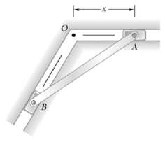
Determine the mass moment of inertia of the 0.9-lb machine component shown with respect to the axis AA′ .
Determine the moments of inertia and the radii of gyration of the steel machine element shown with respect to the x and y axes. (The density of steel is 7850 kg/m3.)
Determine the moments of inertia of the shaded area shown with respect to the x and y axes.
A 20-mm-diameter hole is bored in a 32-mm-diameter rod as shown. Determine the depth d of the hole so that the ratio of the moments of inertia of the rod with and without the hole with respect to the axis AA′ is 0.96.
The motion of a particle is defined by the relation x = t2 − (t − 3)3 where x and t are expressed in meters and seconds, respectively. Determine(a) When the acceleration is zero,(b) The position and velocity of the particle at that time.
The motion of a particle is defined by the relation x = t3 − (t − 2)2 where x and t are expressed in meters and seconds, respectively. Determine(a) When the acceleration is zero,(b) The position and velocity of the particle at that time.
The motion of a particle is defined by the relation x = 5t4 − 4t3 +3t − 2, where x and t are expressed in feet and seconds, respectively. Determine the position, the velocity, and the acceleration of the particle when t = 2 s.
The motion of a particle is defined by the relation x = 6t4 + 8t3 − 14t2 − 10t +16, where x and t are expressed in inches and seconds, respectively. Determine the position, the velocity, and the acceleration of the particle when t = 3 s.
The motion of the slider A is defined by the relation x = 500 sin kt, where x and t are expressed in millimeters and seconds, respectively, and k is a constant. Knowing that k = 10 rad/s, determine the position, the velocity, and the acceleration of slider A when t = 0.05s.
Showing 10400 - 10500
of 18200
First
98
99
100
101
102
103
104
105
106
107
108
109
110
111
112
Last
Step by Step Answers
.PNG)
.PNG)
.PNG)
.PNG)
.PNG)
.PNG)
.PNG)
.PNG)
.PNG)
.PNG)
.PNG)
.PNG)
.PNG)
.PNG)
.PNG)
.PNG)
.PNG)
.PNG)
.PNG)
.PNG)
.PNG)
.PNG)
.PNG)
.PNG)
.PNG)
.PNG)
.PNG)
.PNG)
.PNG)
.PNG)
.PNG)
.PNG)
.PNG)
.PNG)
.PNG)
.PNG)
.PNG)
.PNG)
.PNG)
.PNG)
.PNG)
.PNG)
.PNG)
.PNG)
.PNG)
.PNG)
.PNG)
.PNG)
.PNG)
.PNG)
.PNG)
.PNG)
.PNG)
.PNG)
.PNG)
.PNG)
.PNG)
.PNG)
.PNG)
.PNG)
.PNG)
.PNG)
.PNG)
.PNG)
.PNG)
.PNG)
.PNG)
.PNG)
.PNG)
.PNG)
.PNG)
.PNG)