New Semester
Started
Get
50% OFF
Study Help!
--h --m --s
Claim Now
Question Answers
Textbooks
Find textbooks, questions and answers
Oops, something went wrong!
Change your search query and then try again
S
Books
FREE
Study Help
Expert Questions
Accounting
General Management
Mathematics
Finance
Organizational Behaviour
Law
Physics
Operating System
Management Leadership
Sociology
Programming
Marketing
Database
Computer Network
Economics
Textbooks Solutions
Accounting
Managerial Accounting
Management Leadership
Cost Accounting
Statistics
Business Law
Corporate Finance
Finance
Economics
Auditing
Tutors
Online Tutors
Find a Tutor
Hire a Tutor
Become a Tutor
AI Tutor
AI Study Planner
NEW
Sell Books
Search
Search
Sign In
Register
study help
engineering
machine elements in mechanical design
Machine Elements In Mechanical Design 6th Edition Robert Mott, Edward Vavrek, Jyhwen Wang - Solutions
Repeat Problem 1 for the following gears in the metric module system. Replace Part (c) with equivalent Pd and Part (d) with nearest standard Pd.N = 28; m = 0.8 Problem 1A gear has 44 teeth of the 20°, full-depth, involute form and a diametral pitch of 12. Compute the following:(a) Pitch
Define backlash, and discuss the methods used to produce it.
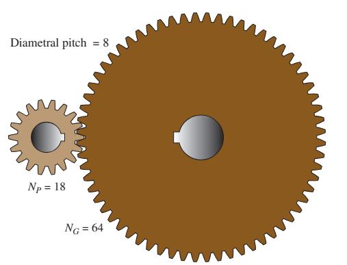
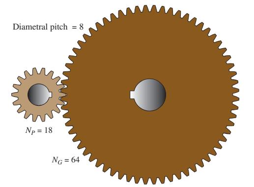
Repeat Problem 20 for the following data:An 8-pitch pinion with 18 teeth mates with a gear having 64 teeth as shown in Figure P8-20. The pinion rotates at 2450 rpm. Compute the following: (a) Center distance (b) Velocity ratio (c) Speed of gear (d) Pitch line speedPd = 4; NP = 20; NG = 92; nP =
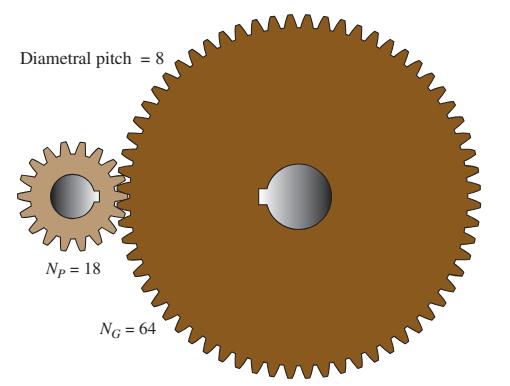
Repeat Problem 20 for the following data:An 8-pitch pinion with 18 teeth mates with a gear having 64 teeth as shown in Figure P8-20. The pinion rotates at 2450 rpm. Compute the following: (a) Center distance (b) Velocity ratio (c) Speed of gear (d) Pitch line speedPd = 20; NP = 30; NG = 68; nP
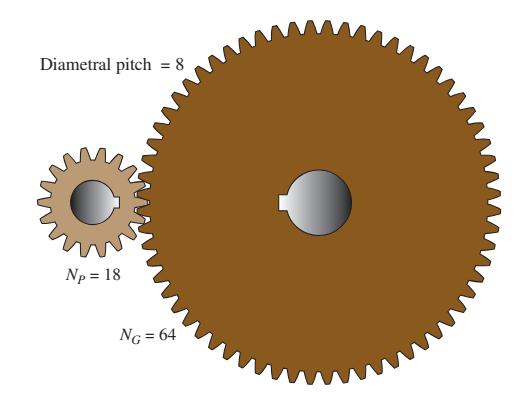
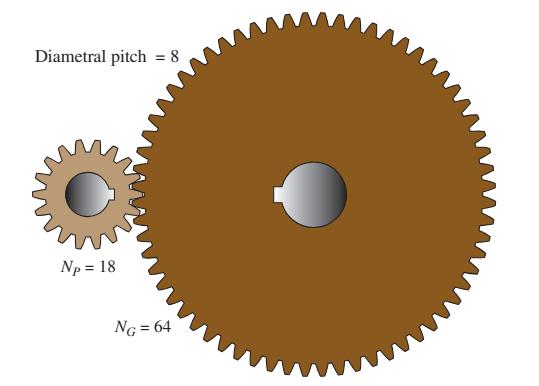
Repeat Problem 20 for the following data:An 8-pitch pinion with 18 teeth mates with a gear having 64 teeth as shown in Figure P8-20. The pinion rotates at 2450 rpm. Compute the following: (a) Center distance (b) Velocity ratio (c) Speed of gear (d) Pitch line speedPd = 64; NP = 40; NG = 250; nP
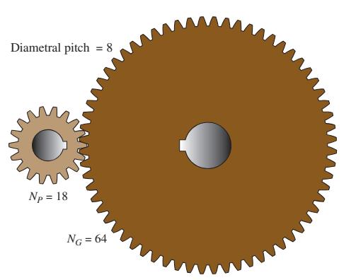
Repeat Problem 20 for the following data:An 8-pitch pinion with 18 teeth mates with a gear having 64 teeth as shown in Figure P8-20. The pinion rotates at 2450 rpm. Compute the following: (a) Center distance (b) Velocity ratio (c) Speed of gear (d) Pitch line speedPd = 12; NP = 24; NG = 88; nP
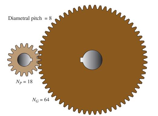
Repeat Problem 20 for the following data:An 8-pitch pinion with 18 teeth mates with a gear having 64 teeth as shown in Figure P8-20. The pinion rotates at 2450 rpm. Compute the following: (a) Center distance (b) Velocity ratio (c) Speed of gear (d) Pitch line speed.m = 2; NP = 22; NG = 68; nP =
Repeat Problem 20 for the following data:An 8-pitch pinion with 18 teeth mates with a gear having 64 teeth as shown in Figure P8-20. The pinion rotates at 2450 rpm. Compute the following: (a) Center distance (b) Velocity ratio (c) Speed of gear (d) Pitch line speed. m = 0.8; NP = 18; NG = 48;
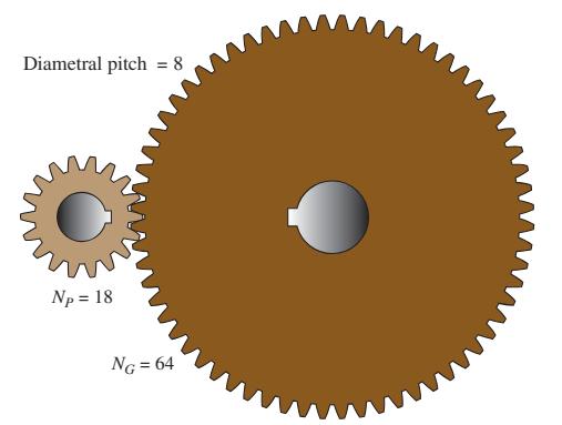
Repeat Problem 20 for the following data:An 8-pitch pinion with 18 teeth mates with a gear having 64 teeth as shown in Figure P8-20. The pinion rotates at 2450 rpm. Compute the following: (a) Center distance (b) Velocity ratio (c) Speed of gear(d) Pitch line speed.m = 4; NP = 36; NG = 45; nP =
Repeat Problem 20 for the following data:An 8-pitch pinion with 18 teeth mates with a gear having 64 teeth as shown in Figure P8-20. The pinion rotates at 2450 rpm. Compute the following: (a) Center distance (b) Velocity ratio (c) Speed of gear(d) Pitch line speed.m = 12; NP = 15; NG = 36; nP =
For Problems 29–32, all gears are made in standard 20°, full-depth, involute form. Tell what is wrong with the following statements: A 20-pitch pinion having 12 teeth mates with a 20-pitch gear having 62 teeth. The pinion rotates at 825 rpm, and the gear at approximately 160 rpm. The center
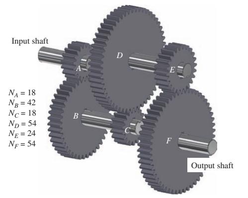
For the gear trains sketched in the given figures, compute the output speed and the direction of rotation of the output shaft if the input shaft rotates at 1750 rpm clockwise. Use Figure P8–37. Input shaft NA = 18 NB = 42 Nc = 18 ND=54 NE = 24 NF = 54 B D F Output shaft
For Problems 29–32, all gears are made in standard 20°, full-depth, involute form. Tell what is wrong with the following statements:A 16-pitch pinion having 24 teeth mates with a 16-pitch gear having 45 teeth. The outside diameter of the pinion is 1.625 in. The outside diameter of the gear is
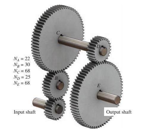
For the gear trains sketched in the given figures, compute the output speed and the direction of rotation of the output shaft if the input shaft rotates at 1750 rpm clockwise.Use Figure P8–38. NA = 22 NB = 30 Nc=68 ND = 25 NE = 68 Input shaft B E Output shaft
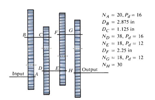
For the gear trains sketched in the given figures, compute the output speed and the direction of rotation of the output shaft if the input shaft rotates at 1750 rpm clockwise. Use Figure P8–39. B Input D A F E| G H Output ΝΑ DB Dc = ND NE DF = = H 20, Pd = 16 2.875 in 1.125 in 38, Pd 16 18,
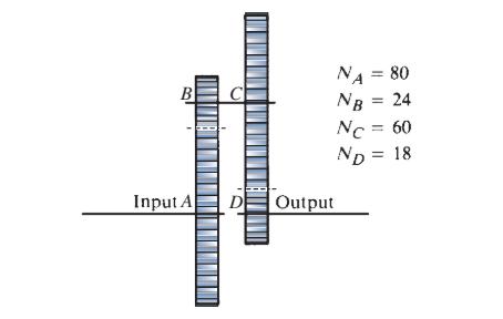
For the gear trains sketched in the given figures, compute the output speed and the direction of rotation of the output shaft if the input shaft rotates at 1750 rpm clockwise. Use Figure P8–40. Input A D NA = 80 NB = 24 Nc = 60 ND = Output 18
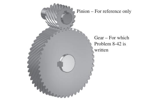
See Figure P8–42. A helical gear has a normal diametral pitch of 12, a normal pressure angle of 20°, 48 teeth, a face width of 1.50 in, and a helix angle of 45°. Compute the circular pitch, normal circular pitch, transverse diametral pitch, axial pitch, pitch diameter, and transverse pressure
A wormgear set has a single-thread worm with a pitch diameter of 1.250 in, a diametral pitch of 10, and a normal pressure angle of 14.5°. If the worm meshes with a wormgear having 40 teeth and a face width of 0.625 in, compute the lead, axial pitch, circular pitch, lead angle, addendum, dedendum,
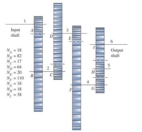
The input shaft for the gear train shown in Figure P8–58 rotates at 3450 rpm cw. Compute the rotational speed and direction of the output shaft.Data in Figure P8–58 Input shaft A N₁ = 18 NB = 82 Nc = 17 ND = 64 NE = 20 NF = 110 NG = 18 NH 18 N₁ =
Three designs are being considered for a wormgear set to produce a velocity ratio of 20 when the wormgear rotates at 90 rpm. All three have a diametral pitch of 12, a worm pitch diameter of 1.000 in, a gear face width of 0.500 in, and a normal pressure angle of 14.5°. One has a single thread worm
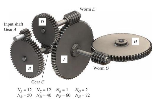
The input shaft for the gear train shown in Figure P8–59 rotates at 12,200 rpm. Compute the rotational speed of the output shaft. Input shaft Gear A B D Gear C N₁ = 12 NB = 50 NC= 12 ND = 40 F NE = 1 N=60 Worm E NG=2 NH = 72 Worm G H
A wormgear set has a double-threaded worm with a normal pressure angle of 20°, a pitch diameter of 0.625 in, and a diametral pitch of 16. Its mating wormgear has 100 teeth and a face width of 0.3125 in. Compute the lead, axial pitch, circular pitch, lead angle, addendum, dedendum, worm outside
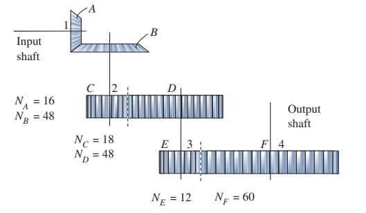
The input shaft for the gear train shown in Figure P8–60 rotates at 6840 rpm. Compute the rotational speed of the output shaft.Data in Figure P8–60 Input shaft N₁ = 16 A NB = 48 C 2 Nc = 18 ND = 48 B E 3 Ng = 12 NF = 60 F 4 Output shaft
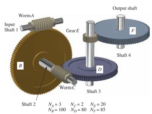
The input shaft for the gear train shown in Figure P8–61 rotates at 2875 rpm. Compute the rotational speed of the output shaft. Input Shaft 1 WormA B Shaft 2 Gear E Worm C NA = 3 NB = 100 D Shaft 3 Nc=2 ND = 80 NE = 20 NF = 85 Output shaft Shaft 4 F
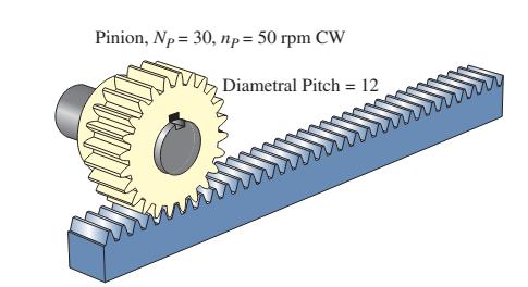
In Figure P8–81, the rack is driven by the pinion that has a rotational speed of 50 rpm. The diametral pitch is 12, NP = 30, and the length of the rack is 7.00 ft. Find the following: Data in Figure P8–81(a) The pitch diameter of the pinion (b) The distance from the pitch line to the back of
Specify the numbers of teeth for the pinion and gear of a single gear pair to produce a velocity ratio of π as closely as possible. Use no fewer than 16 teeth nor more than 24 teeth in the pinion.
A pair of spur gears with 20°, full-depth, involute teeth transmits 7.5 hp. The pinion is mounted on the shaft of an electric motor operating at 1750 rpm. The pinion has 20 teeth and a diametral pitch of 12. The gear has 72 teeth. Compute the following: a. The rotational speed of the
A pair of spur gears with 20°, full-depth, involute teeth transmits 50 hp. The pinion is mounted on the shaft of an electric motor operating at 1150 rpm. The pinion has 18 teeth and a diametral pitch of 5. The gear has 68 teeth. Compute the following: a. The rotational speed of the
A pair of spur gears with 20°, full-depth, involute teeth transmits 0.75 hp. The pinion is mounted on the shaft of an electric motor operating at 3450 rpm. The pinion has 24 teeth and a diametral pitch of 24. The gear has 110 teeth. Compute the following: a. The rotational speed of the
List five geometric factors measured by analytical gear quality measurement devices.
Identify the AGMA standard that is the basis for gear quality measurements and describe the range of quality numbers it includes. Compare that list with the two most recent predecessor standards that had been in use.
Describe the range of hardness that can typically be produced by through-hardening techniques and used successfully in steel gears.
Describe the general nature of the differences among steels produced as Grade 1, Grade 2, and Grade 3.
Suggest at least three applications in which Grade 2 or Grade 3 steel might be appropriate.
Describe three methods of producing gear teeth with strengths greater than can be achieved with through hardening.
What AGMA standard should be consulted for data on the allowable stresses for steels used for gears?
If the design of a steel gear indicates that an allowable bending stress number of 36,000 psi is needed, specify a suitable hardness level for Grade 1 steel. What hardness level would be required for Grade 2 steel?
What level of hardness can be expected for gear teeth that are case-hardened by carburizing?
Name three typical steels that are used in carburizing.
What is the level of hardness that can be expected for gear teeth that are case-hardened by flame or induction hardening?
Name three typical steels that are used for flame or induction hardening. What is an important property of such steels?
What depth should be specified for the case for a carburized gear tooth having a diametral pitch of 6?
What depth should be specified for the case for a carburized gear tooth having a metric module of 6?
A small, powered hand drill is driven by an electric motor running at 3000 rpm. The drill speed is to be approximately 550 rpm. Design the speed reduction for the drill. The power transmitted is 0.25 hp.
Design the gear drive for the wheels of an industrial lift truck. Its top speed is to be 20 mph. It has been decided that the wheels will have a diameter of 12.0 in. A DC motor supplies 20 hp at a speed of 3000 rpm. The design life is 16 hours per day, six days per week, for 20 years.
Design a pair of plastic gears to drive a paper feed roll for an office printer. The pinion rotates at 88 rpm and the gear must rotate between 20 and 22 rpm. The power required is 0.06 hp. Work toward the smallest practical size.
Design a pair of plastic gears to drive the wheels of a small remote control car. The gear is mounted on the axle of the wheel and must rotate between 120 and 122 rpm. The pinion rotates at 430 rpm. The power required is 0.025 hp. Work toward the smallest practical size using unfilled nylon.
A link in a mechanism is to be subjected to a tensile force that varies from 3500 to 500 N in a cyclical fashion as the mechanism runs. It has been decided to use SAE 1040 cold-drawn steel. Complete the design of the link, specifying a suitable cross-sectional shape and dimensions.
A circular rod is to support part of a storage shelf in a warehouse. As products are loaded and unloaded, the rod is subjected to a tensile load that varies from 1800 to 150 lb. Specify a suitable shape, material, and dimensions for the rod.
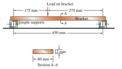
A part of a bracket in the seat assembly of a bus is shown in Figure P5–8. The load varies from 1450 to 140 N as passengers enter and exit the bus. The bracket is made from SAE 1020 hot-rolled steel. Determine the resulting design factor. Data in Figure P5–8. 175 mm Simple supports Load on
A strut in a space frame sees a load that varies from a tensile force of 20.0 kN to a compressive force of 8.0 kN. Specify a suitable shape, material, and dimensions for the strut.
For the bus seat bracket described in Problem 19 and shown in Figure P5–8, propose an alternate design for the bracket, different from that shown in the figure, to achieve a lighter design with a design factor of approximately 4.0. Data in Figure P5–8. 175 mm Simple supports Load on
A part of a latch for a car door is to be made from a straight bar. With each actuation, it sees a tensile force that varies from 780 to 360 N. Small size is important. Complete the design, and specify a suitable shape, material, and dimensions for the rod.
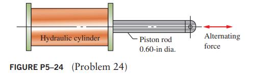
Figure P5–24 shows a hydraulic cylinder that pushes a heavy tool during the outward stroke, placing a compressive load of 400 lb in the piston rod. During the return stroke, the rod pulls on the tool with a force of 1500 lb. Compute the resulting design factor for the 0.60-in-diameter rod when
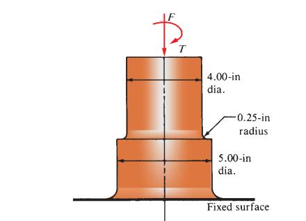
The cast iron cylinder shown in Figure P5–25 carries only an axial compressive load of 75 000 lb. (The torque T = 0.) Compute the design factor if it is made from gray cast iron, Grade 40A, having a tensile ultimate strength of 40 ksi and a compressive ultimate strength of 140 ksi. Data in
A cantilevered boom is part of an assembly machine. A tool with a weight of 500 lb moves continuously from the end of the 60-in beam to a point 10 in from the support. Specify a suitable design for the boom, giving the material, the cross-sectional shape, and the dimensions.
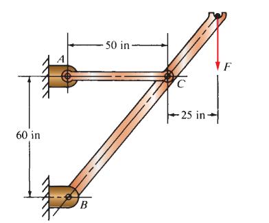
Compute the design factor in the middle portion only of the rod AC in Figure P3–8 if the steady vertical force on the boom is 2500 lb. The rod is rectangular, 1.50 in by 3.50 in, and is made from SAE 1144 cold-drawn steel.Data in Figure P3–8 60 in B -50 in- C -25 in- F
A tensile member in a machine structure is subjected to a steady load of 4.50 kN. It has a length of 750 mm and is made from a steel tube, SAE 1040 hot-rolled, having an outside diameter of 18 mm and an inside diameter of 12 mm. Compute the resulting design factor.
A circular bar of SAE 4140 OQT 1000 steel steps from 12 mm to 10 mm with a fillet radius of 1.5 mm and carries a repeated/reversed 7500 N axial force. Compute the design factor.
Compute the torsional shear stress in a circular shaft having a diameter of 50 mm when subjected to a torque of 800 N • m. If the torque is completely reversed and repeated, compute the resulting design factor. The material is SAE 1040 WQT 1000.
Figure P5–48 shows part of a support bar for a heavy machine, suspended on springs to soften applied loads. The tensile load on the bar varies from 12,500 lb to a minimum of 7500 lb. Rapid cycling for many million cycles is expected. The bar is made from SAE 6150 OQT 1300 steel. Compute the
Compute the torsional shear stress in a circular shaft 0.40 in in diameter that is due to a steady torque of 88.0 lb • in. Specify a suitable aluminum alloy for the rod.
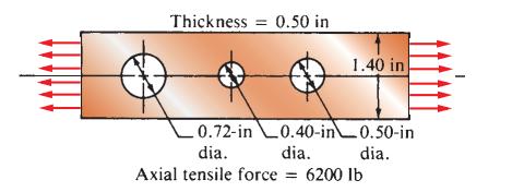
For the flat plate in tension in Figure P3–63, compute the minimum resulting design factor, assuming that the holes are sufficiently far apart that their effects do not interact. The plate is machined from stainless steel, UNS S17400 in condition H1150. The load is repeated and varies from 4000
Specify a suitable material for a hollow shaft with an outside diameter of 40 mm and an inside diameter of 30 mm when transmitting 28 kilowatts (kW) of steady power at a speed of 45 radians per second (rad/s).
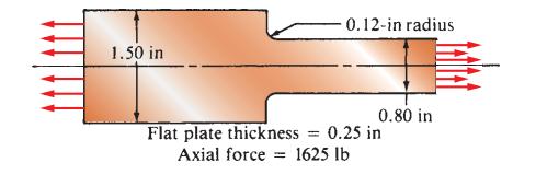
Select a suitable material for the member, considering stress concentrations, for the given loading to produce a design factor of N = 3.Use Figure P3–64. The load is steady. The material is to be some grade of gray cast iron, ASTM A48. Data in Figure P3–64 1.50 in -0.12-in radius 0.80 in Flat
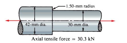
Select a suitable material for the member, considering stress concentrations, for the given loading to produce a design factor of N = 3.Use Figure P3–65. The load varies from 20.0 to 30.3 kN. The material is to be titanium. Data in Figure P3–65 42-mm dia. -1.50-mm radius 30-mm dia. Axial
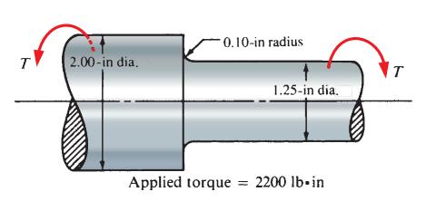
Select a suitable material for the member, considering stress concentrations, for the given loading to produce a design factor of N = 3.Use Figure P3–66. The torque varies from zero to 2200 lb. in. The material is to be steel.Data in Figure P3–66 T 2.00-in dia. -0.10-in radius 1.25-in
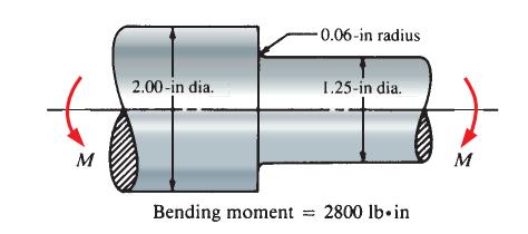
Select a suitable material for the member, considering stress concentrations, for the given loading to produce a design factor of N = 3.Use Figure P3–67. The bending moment is steady. The material is to be ductile iron, ASTM A536. Data in Figure P3–67 M 2.00-in dia. Bending moment -0.06-in
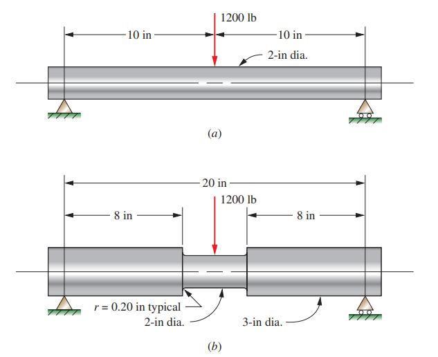
Figure P5–61 shows two designs for a beam to carry a repeated central load of 1200 lb. Which design would have the highest design factor for a given material?Data in Figure P5–61 10 in 8 in r = 0.20 in typical 2-in dia. 1200 lb (a) -20 in 1200 lb (b) -10 in 2-in dia. 3-in dia. 8 in
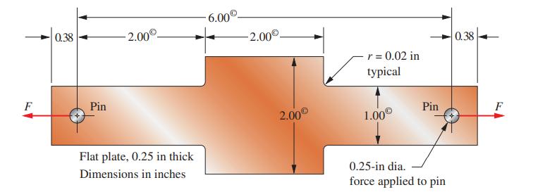
The part shown in Figure P5–64 is made from SAE 1040 HR steel. It is to be subjected to a repeated, one-direction force of 5000 lb applied through two 0.25-in-diameter pins in the holes at each end. Compute the resulting design factor.Data in Figure P5–64 F 0.38 Pin 2.00 Flat plate, 0.25 in
One member of an automatic transfer device in a factory must withstand a repeated tensile load of 800 lb and must not elongate more than 0.010 in in its 25.0-in length. Specify a suitable steel material and the dimensions for the rod if it has a square cross section.
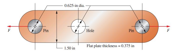
The link shown in Figure P5–66 is subjected to a tensile force that varies from 3.0 to 24.8 kN. Evaluate the design factor if the link is made from SAE 1040 CD steel. Data in Figure P5–66 F Pin 0.625-in dia. DHC Hole 1.50 in Pin Flat plate thickness = 0.375 in F
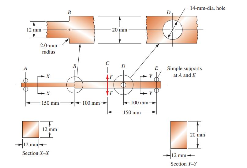
The beam shown in Figure P5–67 carries a repeated, reversed load of 400 N applied at section C. Compute the resulting design factor if the beam is made from SAE 1340 OQT 1300.Data in Figure P5–67. 12 mm A 2.0-mm radius X X 150 mm 12 mm 12 mm Section X-X B B 100 mm C 20 mm AF F D 100 mm 150
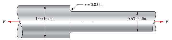
The stepped rod shown in Figure P5–73 is subjected to a direct tensile force that varies from 8500 to 16 000 lb. If the rod is made from SAE 1340 OQT 700 steel, compute the resulting design factor. Data in Figure P5–73 F 1.00-in dia. r = 0.05 in 0.63-in dia. F
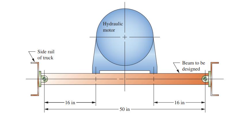
For each of the following problems, complete the requested design to achieve a minimum design factor of 3.0. Specify the shape, the dimensions, and the material for the part to be designed. Work toward an efficient design that will have a low weight. Complete the design of the beam shown in Figure
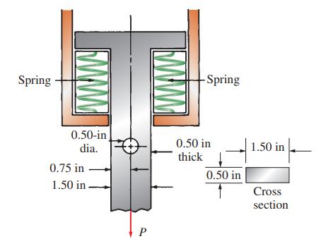
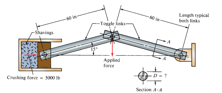
A toggle device is being used to compact scrap steel shavings, as illustrated in Figure P6–16. Design the two links of the toggle to be steel, SAE 5160 OQT 1000, with a circular cross section and pinned ends. The force P required to crush the shavings is 5000 lb. Use N = 3.50.Data in Figure
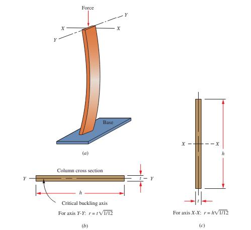
A steel pipe has an outside diameter of 1.60 in, a wall thickness of 0.109 in, and a length of 6.25 ft. Compute the critical load for each of the end conditions shown in Figure 6–2. Use SAE 1020 HR steel.Data in Figure 6–2. Force I Base (a) Column cross section Critical buckling axis For axis
A column has both ends pinned and has a length of 32 in. It is made of SAE 1040 HR steel and has a circular shape with a diameter of 0.75 in. Determine the critical load.
A rectangular steel bar has a cross section 0.50 by 1.00 in and is 8.5 in long. The bar has pinned ends and is made of SAE 4150 OQT 1000 steel. Compute the critical load.
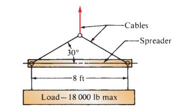
A sling, sketched in Figure P6–18, is to carry 18,000 lb. Design the spreader.Data in Figure P6–18 30° -8 ft Load-18 000 lb max -Cables -Spreader
A rod for a certain hydraulic cylinder behaves as a fixed-free column when used to actuate a compactor of industrial waste. Its maximum extended length will be 10.75 ft. If it is to be made of SAE 1144 OQT 1300 steel, determine the required diameter of the rod for a design factor of 2.5 for an
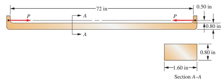
Compute the maximum stress and deflection that can be expected in the steel machine member carrying an eccentric load as shown in Figure P6–32. The load P is 1000 lb. If a design factor of 3 is desired, specify a suitable steel.Data in Figure P6–32. P A A -72 in P 0.50 in 40.80 in 0.80
An aluminum (6063-T4) column is 42 in long and has a square cross section, 1.25 in on a side. If it carries a compressive load of 1250 lb, applied with an eccentricity of 0.60 in, compute the maximum stress in the column and the maximum deflection.
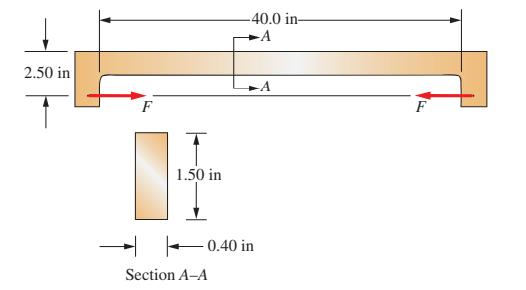
The device shown in Figure P6–38 is subjected to opposing forces F. Determine the maximum allowable load to achieve a design factor of 3. The device is made from aluminum 6061-T6. Data in Figure P6–38 2.50 in F 1.50 in -40.0 in- -A -0.40 in Section A-A F
A hollow square steel tube, 40 in long, is proposed for use as a prop to hold up the ram of a punch press during installation of new dies. The ram weighs 75,000 lb. The prop is made from 4×4×1/4 structural tubing. It is made from steel similar to structural steel, ASTM A500 Grade C. If the load
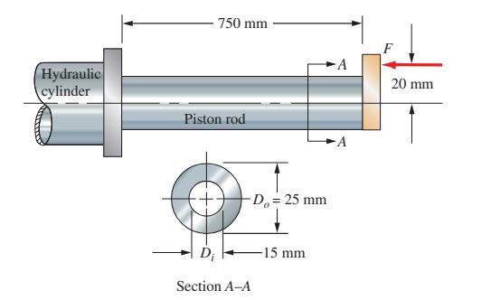
A hydraulic cylinder is capable of exerting a force of 5200 N to move a heavy casting along a conveyor. The design of the pusher causes the load to be applied eccentrically to the piston rod as shown in Figure P6–39. Is the piston rod safe under this loading if it is made from SAE 416 stainless
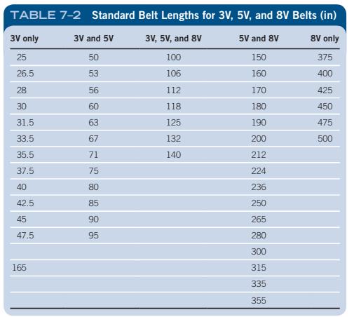
Specify the standard 3V belt length (from Table 7–2) that would be applied to two sheaves with pitch diameters of 5.25 in and 13.95 in with a center distance of no more than 24.0 in. TABLE 7-2 Standard Belt Lengths for 3V, 5V, and 8V Belts (in) 3V, 5V, and 8V 3V
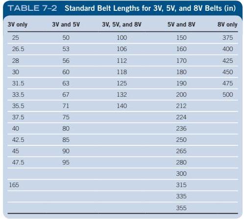
Specify the standard 5V belt length (from Table 7–2) that would be applied to two sheaves with pitch diameters of 8.4 in and 27.7 in with a center distance of no more than 60.0 in. TABLE 7-2 Standard Belt Lengths for 3V, 5V, and 8V Belts (in) 3V only 3V and 5V 3V, 5V, and 8V 5V and
A standard 2-in schedule 40 steel pipe is proposed to be used to support the roof of a porch during renovation. Its length is 13.0 ft. The pipe is made from ASTM A501 structural steel. (a) Determine the safe load on the pipe to achieve a design factor of 3 if the pipe is straight. (b)
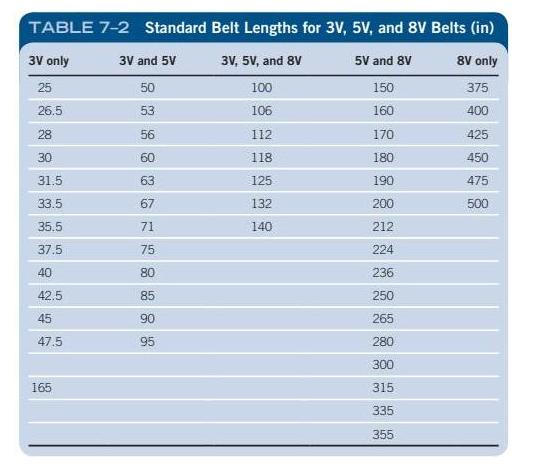
Specify the standard 8V belt length (from Table 7–2) that would be applied to two sheaves with pitch diameters of 13.8 in and 94.8 in with a center distance of no more than 144 in. TABLE 7-2 Standard Belt Lengths for 3V, 5V, and 8V Belts (in) 3V only 3V and 5V 3V, 5V, and 8V 5V and 8V 8V
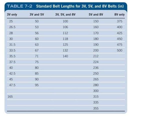
If the small sheave of Problem 4 is rotating at 1160 rpm, compute the linear speed of the belt.Data in Problem 4Specify the standard 5V belt length (from Table 7–2) that would be applied to two sheaves with pitch diameters of 8.4 in and 27.7 in with a center distance of no more than 60.0 in.
Describe a standard 15N belt cross section. To what size belt (inches) would it be closest?
Describe a standard 17A belt cross section. To what size belt (inches) would it be closest?
Describe a standard roller chain, no. 140.
Describe a standard roller chain, no. 60.
Specify a suitable standard chain to exert a static pulling force of 1250 lb.
List three typical failure modes of roller chain.
Determine the power rating of a no. 60 chain, single strand, operating on a 20-tooth sprocket at 750 rpm. Describe the preferred method of lubrication. The chain connects a hydraulic drive with a meat grinder.
Determine the power rating of a no. 40 chain, single strand, operating on a 12-tooth sprocket at 860 rpm. Describe the preferred method of lubrication. The small sprocket is applied to the shaft of an electric motor. The output is to a coal conveyor.
Determine the power rating of a no. 80 chain, single-strand, operating on a 32-tooth sprocket at 1160 rpm. Describe the preferred method of lubrication. The input is an internal combustion engine, and the output is to a fluid agitator.
Showing 1600 - 1700
of 1879
First
5
6
7
8
9
10
11
12
13
14
15
16
17
18
19
Step by Step Answers