New Semester
Started
Get
50% OFF
Study Help!
--h --m --s
Claim Now
Question Answers
Textbooks
Find textbooks, questions and answers
Oops, something went wrong!
Change your search query and then try again
S
Books
FREE
Study Help
Expert Questions
Accounting
General Management
Mathematics
Finance
Organizational Behaviour
Law
Physics
Operating System
Management Leadership
Sociology
Programming
Marketing
Database
Computer Network
Economics
Textbooks Solutions
Accounting
Managerial Accounting
Management Leadership
Cost Accounting
Statistics
Business Law
Corporate Finance
Finance
Economics
Auditing
Tutors
Online Tutors
Find a Tutor
Hire a Tutor
Become a Tutor
AI Tutor
AI Study Planner
NEW
Sell Books
Search
Search
Sign In
Register
study help
engineering
machine elements in mechanical design
Theory Of Machines Kinematics And Dynamics 3rd Edition Sadhu Singh - Solutions
The net effect of creep in belts is to(a) increase the speed of driven pulley(b) decrease the speed of driven pulley(c) increase the power output(d) decrease the power output.
A flat belt drive is required to transmit \(20 \mathrm{~kW}\) at \(300 \mathrm{rpm}\) of \(2 \mathrm{~m}\) diameter pulley. The angle of contact is \(170^{\circ}\) and coefficient of friction between belt and pulley is 0.30 . The permissible stress for belt material is \(3 \mathrm{MPa}\). Thickness
A shaft running at \(500 \mathrm{rpm}\) carries a pulley \(1 \mathrm{~m}\) diameter and drives another pulley by means of ropes with a speed ratio of 2:1. The drive transmits \(200 \mathrm{~kW}\). Angle of groove is \(40^{\circ}\) and distance between pulley centres is \(2 \mathrm{~m}\). The
If the difference between tight and slack side tensions for a leather belt does not exceed \(100 \mathrm{~N} / \mathrm{cm}\) of width for a belt \(5 \mathrm{~mm}\) thick, find the maximum stress in the belt. Assume the following data:Angle of lap \(=170^{\circ}\), coefficient of friction \(=0.25\),
The initial tension in a flat belt drive is \(1800 \mathrm{~N}\) and angle of lap on the smaller pulley is \(170^{\circ}\). The coefficient of friction between belt and pulley surface is 0.25 . The pulley diameter is \(0.9 \mathrm{~m}\) and runs at \(540 \mathrm{rpm}\). Neglecting centrifugal
It is required to reduce speed from 360 to \(120 \mathrm{rpm}\) by the use of chain drive. The driving sprocket has 10 teeth. Calculate: (a) the number of teeth on the follower, (b) the pitch of chain if pitch circle diameter of follower is \(0.5 \mathrm{~m}\), (c) the pitch circle diameter of
A rope pulley having a mean diameter of \(1.5 \mathrm{~m}\) rotates at \(90 \mathrm{rpm}\); angle of lap of ropes \(=170^{\circ}\); angle of groove \(=45^{\circ}\), safe tension per rope \(=750 \mathrm{~N}\), and coefficient of friction between the ropes and sides of groove \(=0.25\). Calculate the
A belt of density \(1000 \mathrm{~kg} / \mathrm{m}^{3}\) has a maximum permissible stress of \(2.5 \mathrm{MPa}\). Calculate the maximum power that can be transmitted by a belt of \(200 \mathrm{~mm} \times 12 \mathrm{~mm}\) size if the ratio of tensions is 2 .
Determine the maximum power that can be transmitted by a belt of \(100 \mathrm{~mm} \times 10 \mathrm{~mm}\) size with an angle of lap of \(160^{\circ}\). The belt density is \(1000 \mathrm{~kg} / \mathrm{m}^{3}\) and coefficient of friction is 0.25 . The tension in the belt should not exceed \(1.5
The included angle of a V-grooved pulley is \(30^{\circ}\). The belt is \(20 \mathrm{~mm}\) deep and maximum width is \(20 \mathrm{~mm}\). The mass of belt is \(0.35 \mathrm{~kg}\) per metre length and maximum allowable stress is \(1.4 \mathrm{MPa}\). Determine the maximum power that can be
A pulley used to transmit power by means of ropes has a diameter of \(3.6 \mathrm{~m}\) and has 15 grooves of \(45^{\circ}\) angle. The angle of contact is \(170^{\circ}\) and coefficient of friction between ropes and groove side is 0.28 . The maximum possible tension in the ropes is \(960
What is the function of a steering gear?
Watt mechanism is capable of generating(a) approximate straight line(b) exact straight line(c) approximate circular path(d) exact circular path.
A shaft running at \(1200 \mathrm{rpm}\) is connected to a second shaft by a Hooke's joint. The angle between the axes of the shafts is \(15^{\circ}\). Determine the velocity and acceleration of the driven shaft when it has turned through an angle of \(10^{\circ}\) from the plane containing the
Define a steering gear.
Scott-Russel mechanism for generating straight line has(a) four lower kinematic turning pairs(b) two lower kinematic turning pairs and one lower kinematic sliding pairs(c) one lower kinematic turning pair and two lower kinematic sliding pairs(d) two lower kinematic turning pairs and two lower
The driving shaft of a Hooke's joint is rotating at a uniform speed of \(600 \mathrm{rpm}\). The speed of the driven shaft must be 575 and \(625 \mathrm{rpm}\). Determine the maximum permissible angle between the shafts.
List the approximate straight line mechanisms.
In automobiles, the power is transmitted from gear box to differential through(a) bevel gears(b) knuckle joint(c) Hooke’s joint(d) Cotter joint.
The axes of two shafts connected by a Hooke's joint are inclined at \(20^{\circ}\). At what positions of the driving shaft, the velocities of two shafts are equal? State whether the accelerations are positive or negative at these positions.If the driving shaft rotates at \(1800 \mathrm{rpm}\),
Name the exact straight line mechanisms.
Automobile steering gear is an example of(a) higher pair(b) sliding pair(c) turning pair(d) lower pair.
Two shafts connected by a Hooke's joint have their axes inclined at \(20^{\circ}\). The driving shaft rotates at \(1440 \mathrm{rpm}\) and the driven shaft carries a flywheel of mass \(20 \mathrm{~kg}\). The radius of gyration is \(10 \mathrm{~cm}\). Find the maximum torque in the driven shaft.
What is a pantograph? What are its uses?
The number of links in a pantograph mechanism is equal to(a) 2(b) 3(c) 4(d) 5
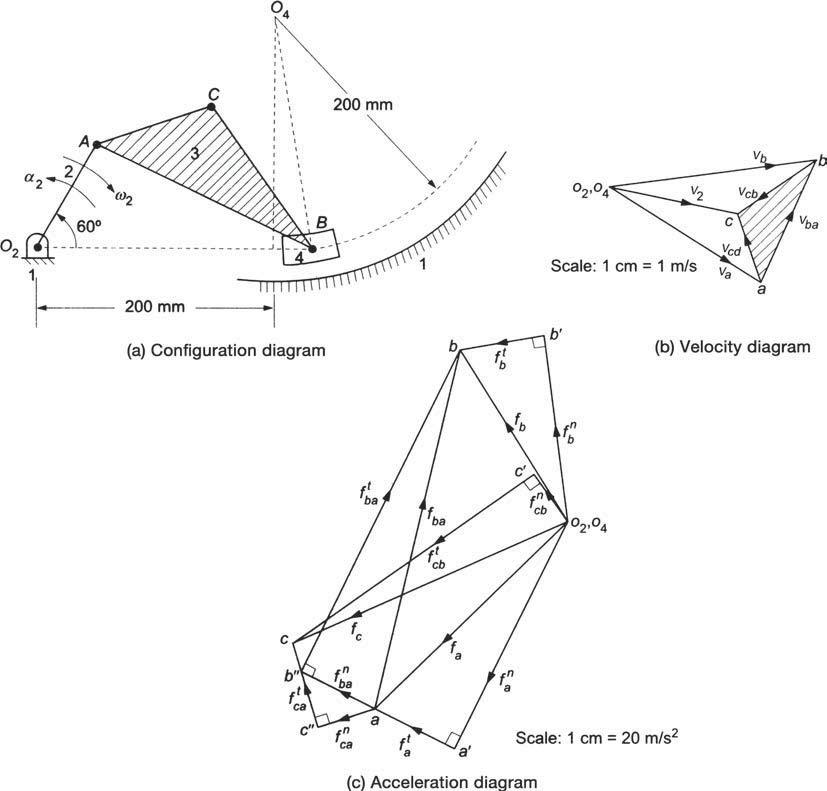
In the mechanism shown in Fig.3.35(a), the link 2 rotates with angular velocity of \(30 \mathrm{rad} / \mathrm{s}\) and an angular acceleration of \(240 \mathrm{rad} / \mathrm{s}^{2}\). Determine(a) the acceleration of points \(B\) and \(C\),(b) the angular accelerations of link 3 and 4 and(c) the
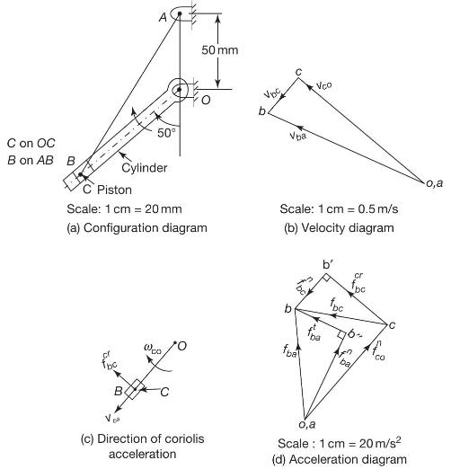
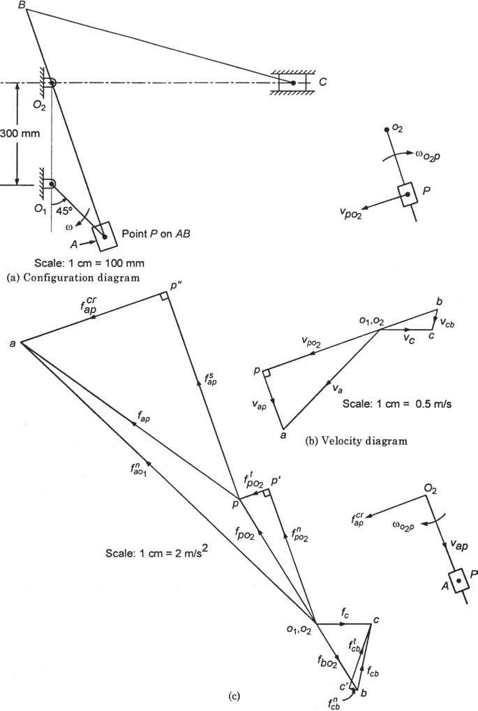
The kinematic diagram of one of the cylinders of a rotary engine is shown in Fig.3.34(a). The crank \(O A\) which is vertical and fixed, is \(50 \mathrm{~mm}\) long. The length of connecting \(\operatorname{rod} A B\) is \(125 \mathrm{~mm}\). The line of stroke \(O B\) is inclined at \(50^{\circ}\)
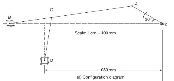
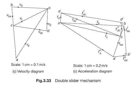
In the mechanism shown in Fig.3.33, the crank \(O A\) rotates at \(20 \mathrm{rpm}\) anti-clockwise and gives motion to the sliding blocks \(B\) and \(D\). The dimensions of the various links are: \(O A=300 \mathrm{~mm}, A B=1200 \mathrm{~mm}\),\(B C=450 \mathrm{~mm}\), and \(C D=450
The crank of an engine \(250 \mathrm{~mm}\) long rotates at a uniform speed of \(240 \mathrm{rpm}\). The ratio of connecting rod length to crank radius is 4 . Determine(a) the acceleration of the piston,(b) the angular acceleration of the rod, and(c) the acceleration of a point \(X\) on the
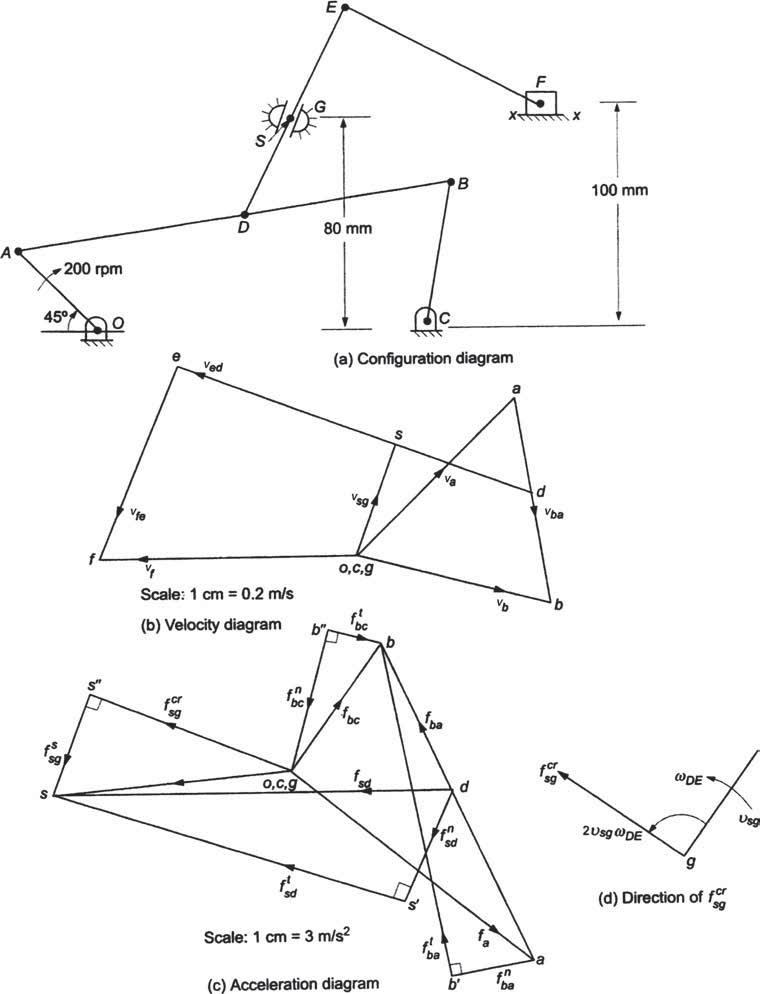
In the swivelling point mechanism shown in Fig.3.31(a), \(O A=25 \mathrm{~mm}, A B=150 \mathrm{~mm}, A D=D E\), \(D E=150 \mathrm{~mm}, E F=100 \mathrm{~mm}, B C=60 \mathrm{~mm}, D S=40 \mathrm{~mm}\), and \(O C=150 \mathrm{~mm}\). Crank \(O A\) rotates at \(200 \mathrm{rpm}\). Determine the
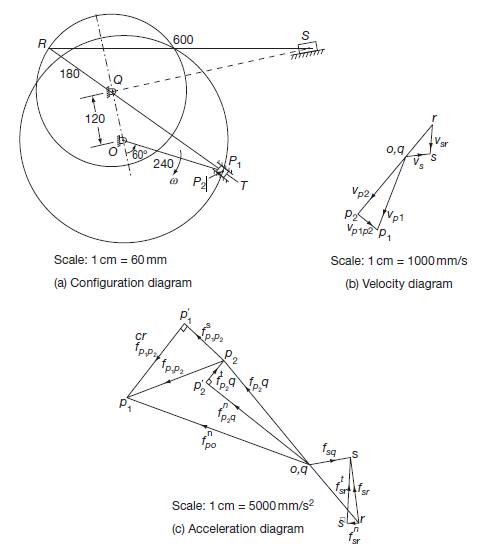
Fig.3.30 depicts the structure of Whitworth quick return mechanism used in reciprocating machine tools. The various dimensions of the mechanism for a specified stroke of the tool are:\[ O Q=120 \mathrm{~mm}, O P=240 \mathrm{~mm}, R Q=180 \mathrm{~mm} \text {, and } R S=600 \mathrm{~mm} \text {. }
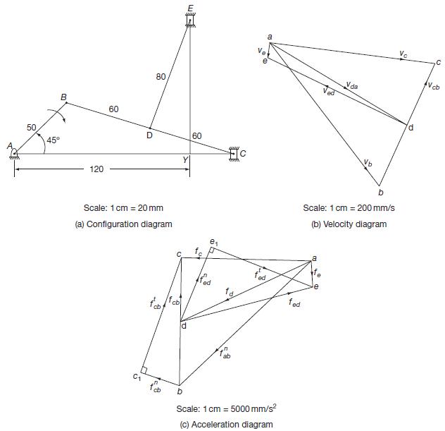
In the mechanism shown in Fig.3.29, link \(A B\) rotates clockwise at a speed of \(240 \mathrm{rpm}\). At the instant shown, find the velocity and acceleration of slider \(C\) as well as those of slider \(E . A B=50 \mathrm{~mm}\), \(B C=120 \mathrm{~mm}, B D=D C=60 \mathrm{~mm}, D E=80
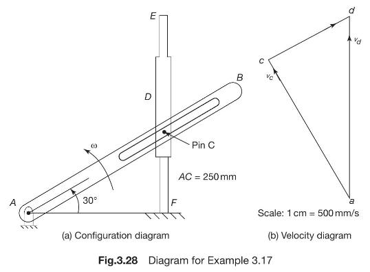
Bar \(A B\) is connected by pin \(C\) to slider \(D\) that slides along the fixed vertical rod \(E F\) as shown in Fig.3.28. Find the velocity and acceleration of the slider \(D\) if the bar \(A B\) rotates at a constant angular velocity of \(10 \mathrm{rad} / \mathrm{s}\) in counter-clockwise
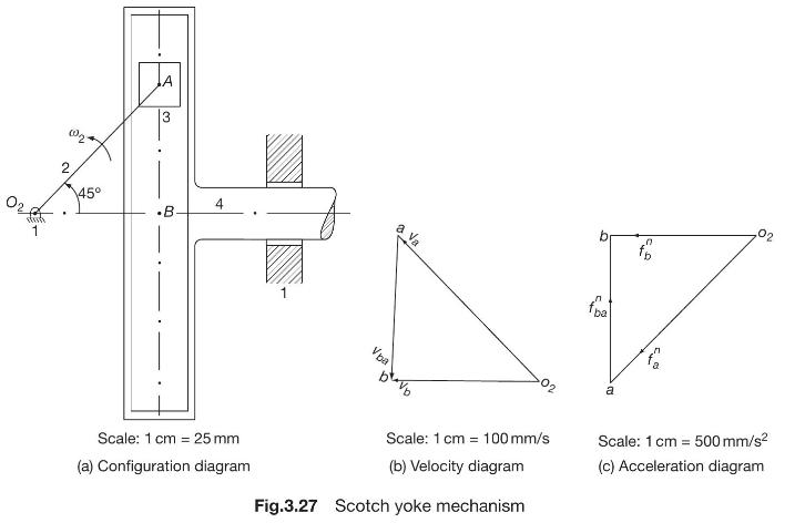
For the Scotch yoke mechanism shown in Fig.3.27, find the velocity and acceleration of point \(B\). \(\omega_{2}=5 \mathrm{rad} / \mathrm{s}\), and \(O_{2} A=100 \mathrm{~mm}\). 2 45 3 .B. Scale: 1 cm 25 mm = (a) Configuration diagram a va Vpa n fra 6 a Scale: 1 cm 100 mm/s (b) Velocity diagram
In Example 3.14 , calculate analytically, the acceleration of the piston and angular acceleration of the rod.
The crank of an engine \(300 \mathrm{~mm}\) long rotates at a uniform speed of \(300 \mathrm{rpm}\). The ratio of connecting rod length to crank radius is 4 . Determine(a) acceleration of the piston.(b) angular acceleration of the rod, and(c) acceleration of a point \(X\) on the connecting rod at
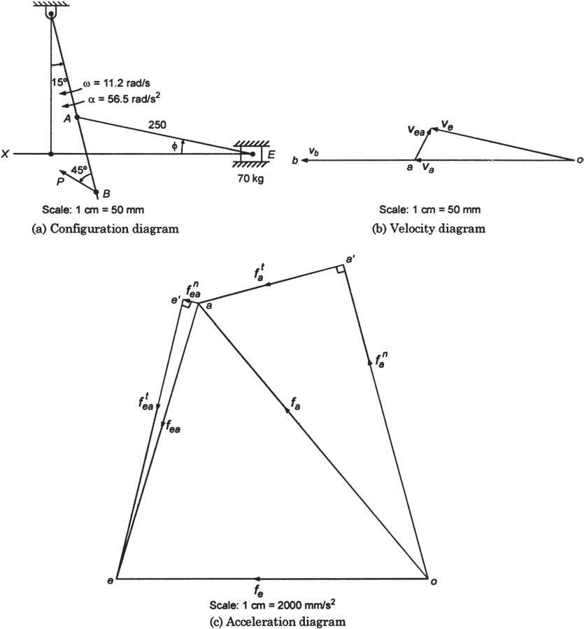
A part of a mechanism which operates a horizontally sliding block \(E\) is shown in Fig.3.23(a). In the given configuration, the lever \(O B\) swings about \(O\) in the clockwise direction with an angular velocity of 11.2 \(\mathrm{rad} / \mathrm{s}\) and an angular acceleration of \(56.5
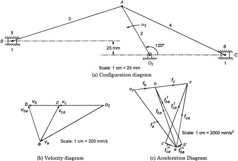
A double slider-crank mechanism is shown in Fig.3.22(a). Crank 2 rotates at constant angular speed \(\omega_{2}=10 \mathrm{rad} / \mathrm{s}\). Determine the velocity and acceleration of each slider. \(O_{2} A=1000 \mathrm{~mm}, A B=200 \mathrm{~mm}\), and \(A C=200 \mathrm{~mm}\). B 1 5 3 25 mm
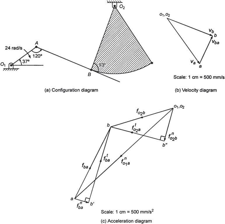
In the mechanism shown in Fig.3.21(a), the link \(O_{1} A\) rotates at \(24 \mathrm{rad} / \mathrm{s}\). Find the velocity and acceleration of point \(B\). \(O_{1} A=75 \mathrm{~mm}, A B=200 \mathrm{~mm}\), and \(O_{2} B=2000 \mathrm{~mm}\). 24 rad/s 120 37 B 93 (a) Configuration diagram 02 01,02
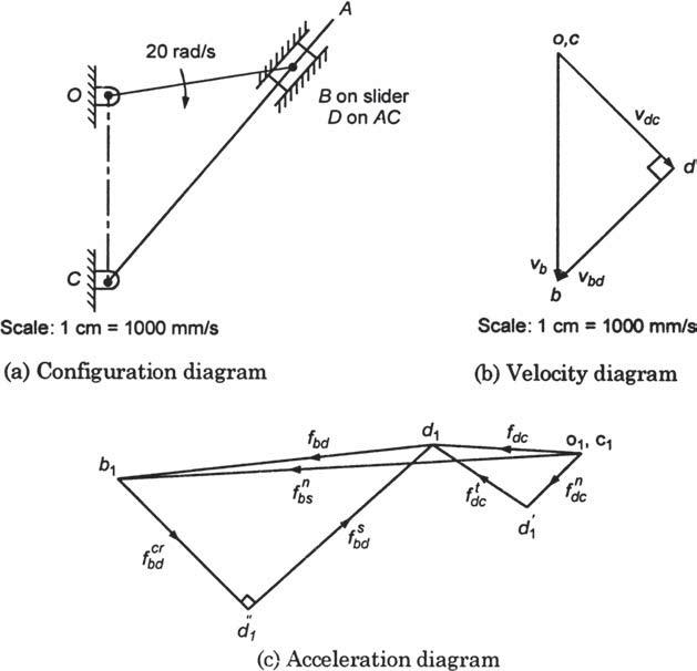
Draw the acceleration diagram for the shaper mechanism shown in Fig.3.20(a). \(O B=150 \mathrm{~mm}\), \(C B=225 \mathrm{~mm}, O C=150 \mathrm{~mm}\). Find the coriolis acceleration of slider \(B\). A 20 rad/s B on slider D on AC C Scale: 1 cm = 1000 mm/s (a) Configuration diagram b .cr fbd d O,C
For the slider-crank mechanism shown in Fig.3.19(a), determind(a) acceleration of slider \(B\), (b), acceleration of point \(C\), and(c) acceleration of link \(A B\). The crank \(O A\) rotates at \(180 \mathrm{rpm} . O A=500\) \(\mathrm{mm}, A B=1500 \mathrm{~mm}\), and \(A C=250 \mathrm{~mm}\). 0
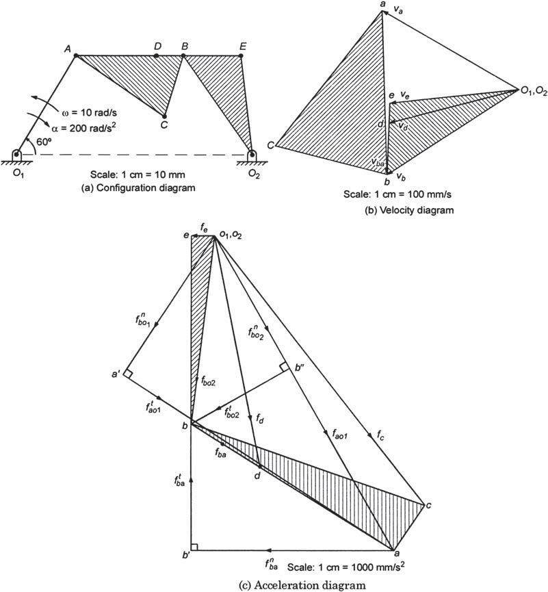
For the mechanism shown in Fig.3.18(a), find the angular accelerations of the links \(A B, B O_{2}\) and the linear accelerations of points \(C, D\), and E. \(\omega=10 \mathrm{rad} / \mathrm{s}, \alpha=200 \mathrm{rad} / \mathrm{s}^{2}\).\[ \begin{gathered} O_{1} \mathrm{O}_{2}=100 \mathrm{~mm},
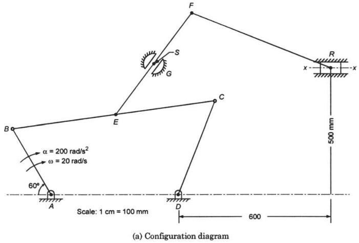
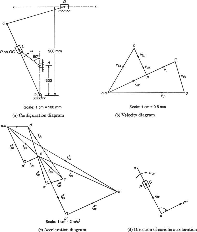
In the swivelling joint mechanism shown in Fig. 3.17 (a), \(A B=300 \mathrm{~mm}, B C=800 \mathrm{~mm}, C D=400 \mathrm{~mm}\), \(A D=500 \mathrm{~mm}, B E=400 \mathrm{~mm}, E F=500 \mathrm{~mm}, E S=250 \mathrm{~mm}\), and \(F R=600 \mathrm{~mm}\). The crank \(A B\) rotates at \(20 \mathrm{rads} /
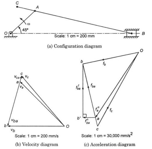
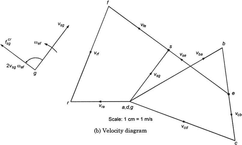
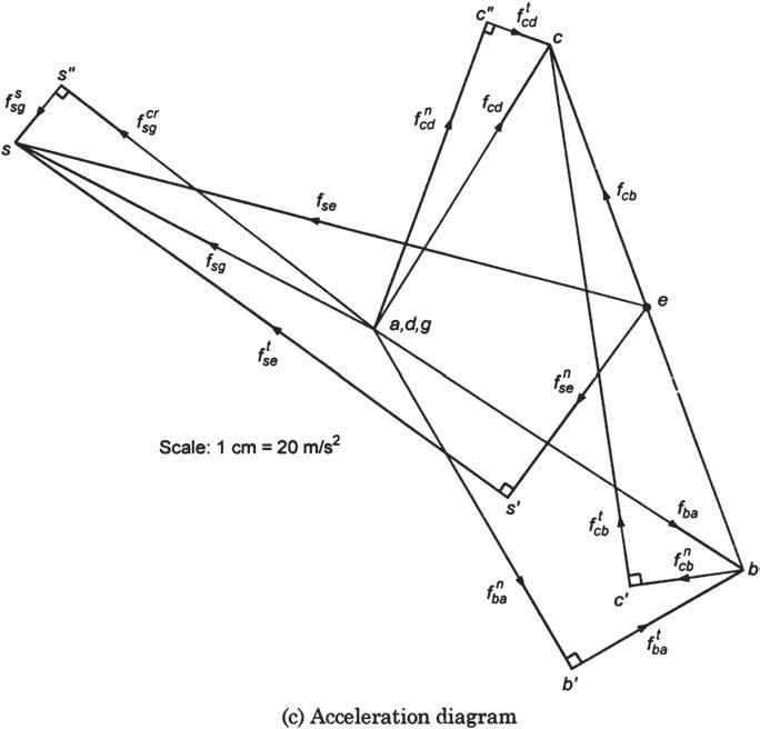
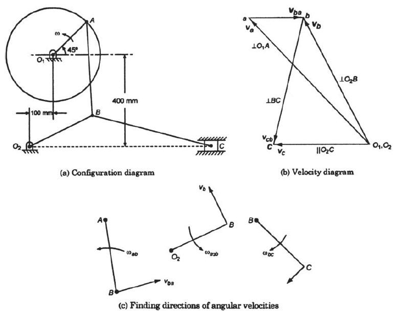
Draw the acceleration diagram for the Whitworth mechanism shown in Fig.3.15(a).\[ \begin{aligned} O_{1} O_{2} & =300 \mathrm{~mm}, O_{1} A=200 \mathrm{~mm} \\ A B & =700 \mathrm{~mm}, B C=800 \mathrm{~mm} \\ \angle A O_{1} O_{2} & =45^{\circ} . \end{aligned} \]The crank \(O_{1} A\)
In the crank and slotted lever type quick return motion mechanism shown in Fig.3.14(a), the crank \(A B\) rotates at \(120 \mathrm{rpm}\). Determine(a) velocity of ram at \(D\),(b) magnitude of Coriolis acceleration component, and(c) acceleration of ram at \(D \cdot A B=200 \mathrm{~mm}, O C=800
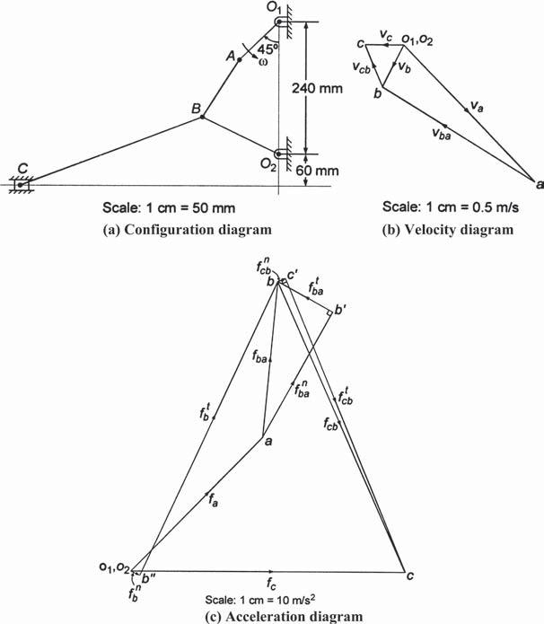
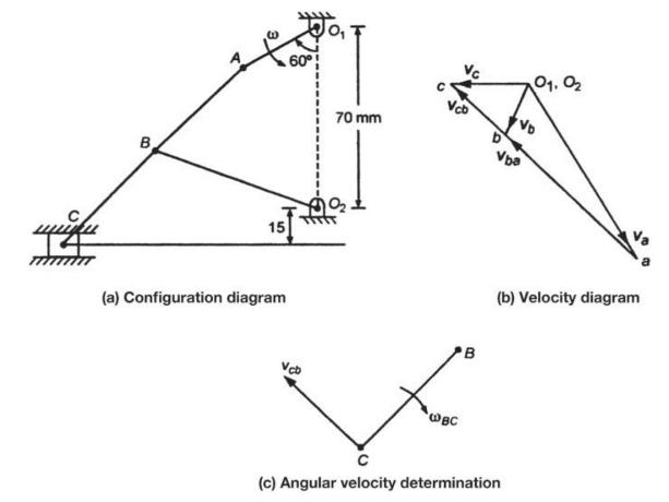
In the mechanism shown in Fig.3.11(a), determine the acceleration of the slider \(C . O_{1} A=100 \mathrm{~mm}, A B=\) \(120 \mathrm{~mm}, O_{2} B=150 \mathrm{~mm}\), and \(B C=350 \mathrm{~mm}\). The crank \(O_{1} A\) rotates at \(240 \mathrm{rpm}\). B 45% A, 240 mm Vcb Vc_01,02 Vba 02 60 mm a
In the slider-crank shown in Fig.3.10(a), the lengths of the various links are:\[ O A=A C=200 \mathrm{~mm}, A B=600 \mathrm{~mm}, \angle A O B=30^{\circ} \text {. } \]The crank rotates at \(10 \mathrm{rad} / \mathrm{s}\). Determine(a) the acceleration of the connecting rod \(A B\),(b) acceleration
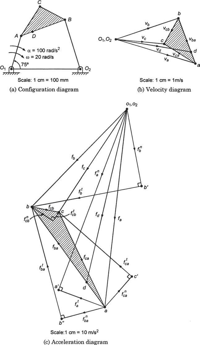
A four-bar mechanism with ternary link is shown in Fig.3.9(a). The lengths of various links is given as below:\[ \begin{aligned} O_{1} O_{2} & =600 \mathrm{~mm}, O_{1} A=300 \mathrm{~mm}, A B=400 \mathrm{~mm}, O_{2} B=450 \mathrm{~mm} \\ A C & =300 \mathrm{~mm}, B C=250 \mathrm{~mm}, A
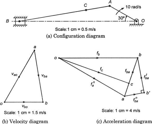
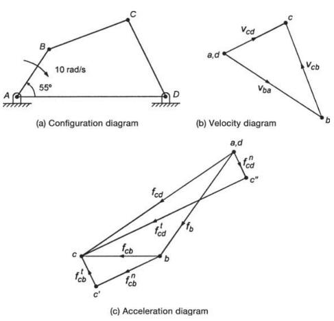
In the four-bar mechanism shown in Fig.3.8, the lengths of the various links are: \(A B=190 \mathrm{~mm}\), \(B C=C D=280 \mathrm{~mm}, A D=500 \mathrm{~mm}, \angle B A D=55^{\circ}\). The crank \(A B\) rotates at \(10 \mathrm{rad} / \mathrm{s}\) in the clockwise direction. Determine(a) the
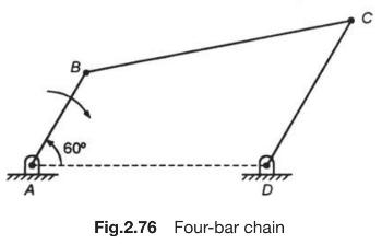
The dimensions of a four-bar chain shown in Fig. 2.76 are: \(A D=B E=120 \mathrm{~mm}, A B=30 \mathrm{~mm}\) and \(C D=60 \mathrm{~mm}\). The crank \(A B\) rotates at \(100 \mathrm{rpm}\). Determine the angular speed of link \(C D\). A 60 D Fig.2.76 Four-bar chain C
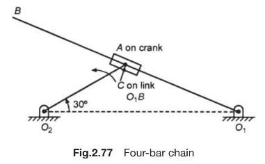
In the mechanism shown in Fig.2.77, \(O_{1} O_{2}=210 \mathrm{~mm}, O_{1} B=300 \mathrm{~mm}\) and \(O_{2} A=60 \mathrm{~mm}\). The crank \(O_{2} A\) rotates at \(300 \mathrm{rpm}\) in the ccw direction. Find (a) angular speed of link \(O_{1} A\), and (b) velocity of slider. B 30 02 A on crank Con
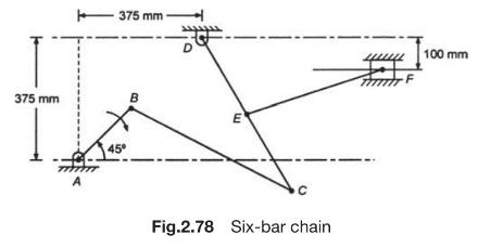
The dimensions of the various links of the mechanism shown in Fig.2.78 are: \(A D=D E=150\) \(\mathrm{mm}, B C=C D=450 \mathrm{~mm}, E F=375 \mathrm{~mm}\).The crank \(A B\) rotates at \(120 \mathrm{rpm}\). The lever \(D C\) oscillates about the fixed point \(D\). Determine (a) velocity of slider
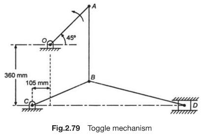
In the toggle mechanism shown in Fig.2.79, the crank \(O A\) rotates at \(180 \mathrm{rpm}\) and the slider is constrained to move on a horizontal path. \(O A=180 \mathrm{~mm}, B C=240 \mathrm{~mm}, A B=360 \mathrm{~mm}\), and \(B D=540 \mathrm{~mm}\)Find (a) velocity of slider \(D\), (b) angular
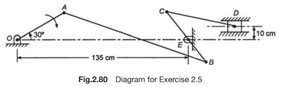
The crank \(O A\) of the mechanism shown in Fig. 2.80 rotates at \(100 \mathrm{rpm}\) clockwise. Using instantaneous centre method determine the linear velocities of points \(B, C\) and \(\mathrm{D}\), and angular speeds of links \(A B, B C\) and \(C D\). 30 135 cm Fig.2.80 Diagram for Exercise
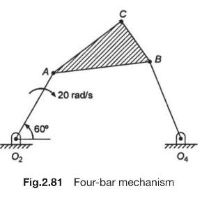
Find the velocity of point \(C\) in the mechanism shown in Fig. 2.81 by using relative velocity method. Crank \(O_{2} A\) rotates at \(20 \mathrm{rad} / \mathrm{s}\) clockwise. 60 20 rad/s B 02 Fig.2.81 Four-bar mechanism 04
In the mechanism shown in Fig.2.14(a), the crank \(O_{1} A\) rotates at a uniform speed of \(650 \mathrm{rpm}\). Determine the linear velocity of the slider \(C\) and the angular speed of the link \(B C . O_{1} A=30 \mathrm{~mm}, A B=45 \mathrm{~mm}\), \(B C=50 \mathrm{~mm}, O_{2} B=65
The slider \(C\) of the toggle mechanism shown in Fig.2.15(a) is constrained to move on a horizontal path. The crank \(O_{1} A\) rotates in the counterclockwise direction at a uniform speed of \(180 \mathrm{rpm}\).\[ O_{1} A=200 \mathrm{~mm}, A B=400 \mathrm{~mm}, O_{2} B=300 \mathrm{~mm} \text {,
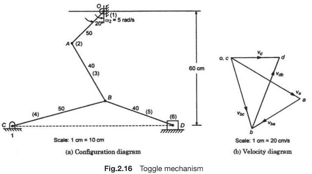
Determine the mechanical advantage of the toggle mechanism shown in Fig.2.16(a). (4) 50 A (2) 50 (1). 2025 rad/s 40 03 (3) 40 60 cm VDC Scale: 1 cm = 10 cm (a) Configuration diagram Fig.2.16 Toggle mechanism Scale: 1 cm = 20 cm/s (b) Velocity diagram
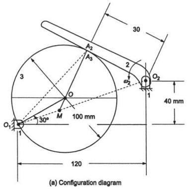
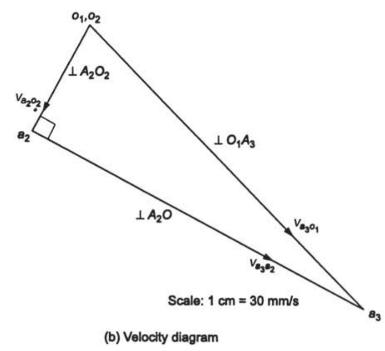
Determine the angular velocity of the follower 3 and the velocity of sliding at the point of contact in Fig.2.17(a). The speed of driver link 2 is \(3 \mathrm{rad} / \mathrm{s}\). 3 30 Az As 30 50 M 100 mm 40 mm 120 (a) Configuration diagram
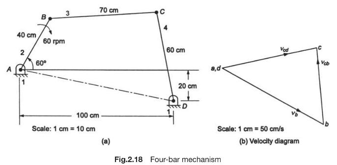
The crank \(A B\) of a four-bar mechanism shown in Fig.2.18(a) rotates at \(60 \mathrm{rpm}\) clockwise. Determine the relative angular velocities of the coupler to the crank and the lever to the coupler. Find also the rubbing velocities at the surface of pins \(25 \mathrm{~mm}\) radius at the
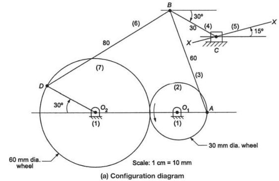
Wheel 2 in Fig.2.19(a) rotates at \(1500 \mathrm{rpm}\) and is driving the wheel 7 pivoted at \(O_{2}\). Determine the linear velocity of slider and angular velocities of links 3,4 and 6. (6) B 30 (7) 80 00 (2) 30 (4) x- 60 (3) 30 (1) (5) 15 60 mm dia.. wheel Scale: 1 cm 10 mm (a) Configuration
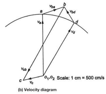
The dimensions of the mechanism for hydraulic riveter, as shown in Fig.2.20(a), are: \(O A=200 \mathrm{~mm}\), \(A B=210 \mathrm{~mm}, A D=550 \mathrm{~mm}\) and \(B C=330 \mathrm{~mm}\).Determine the velocity ratio between the piston \(C\) and ram \(D\). Also calculate the efficiency of the
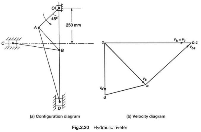
Crank \(O A\) in Fig.2.21(a) is \(80 \mathrm{~mm}\) long and rotates clockwise about \(O\) at \(120 \mathrm{rpm}\). The connecting rod \(A B\) is \(450 \mathrm{~mm}\) long. Point \(C\) on \(A B\) is such that \(A C=150 \mathrm{~mm}\). A rod \(C E=400 \mathrm{~mm}\) is attached at point \(C\) which
An engine crankshaft drives a reciprocating pump through a mechanism, as shown in Fig.2.22(a). The crank \(O A\) rotates in the counter-clockwise direction at \(150 \mathrm{rpm}\). The diameter of the pump piston at \(F\) is \(180 \mathrm{~mm}\) and \(O A=175 \mathrm{~mm}, A B=650 \mathrm{~mm}, C
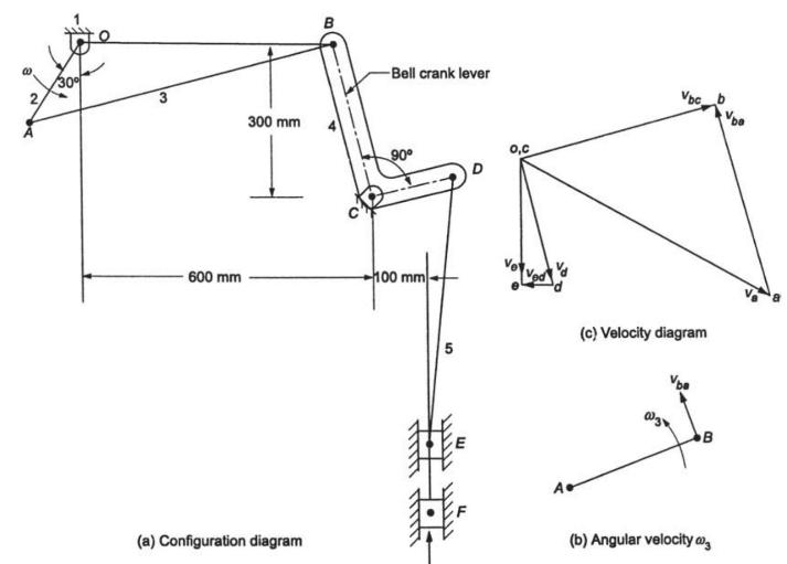
The various dimensions of the mechanism, as shown in Fig.2.23(a), are \(O A=120 \mathrm{~mm}, A B=500 \mathrm{~mm}\), \(B C=120 \mathrm{~mm}, C D=300 \mathrm{~mm}\), and \(D E=150 \mathrm{~mm}\). The crank \(O A\) rotates at \(150 \mathrm{rpm}\). The bell crank lever is DE. Determine the absolute
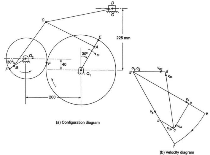
In the mechanism shown in Fig.2.24(a), the crank \(O_{1} A\) and \(O_{2} B\) are 100 and \(50 \mathrm{~mm}\), respectively. The diameters of wheels with centres \(O_{1}\) and \(O_{2}\) are 260 and \(150 \mathrm{~mm}\), respectively. \(B C=A C=200 \mathrm{~mm}\), \(C D=250 \mathrm{~mm}\). The wheels
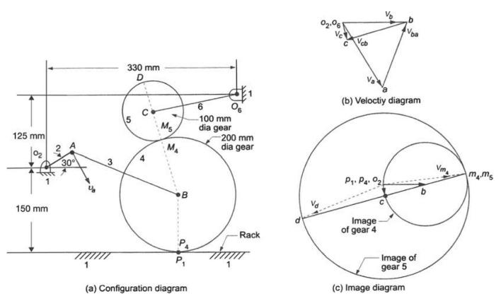
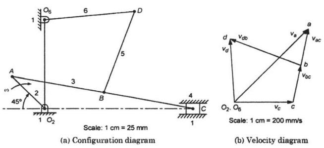
In the mechanism shown in Fig.2.25(a), \(v_{a}=120 \mathrm{~m} / \mathrm{s}\). Determine the angular velocities \(\omega_{4}, \omega_{5}\) of the two gears and the velocity \(v_{d}\) on gear \(5 . O_{2} A=50 \mathrm{~mm}, A B=200 \mathrm{~mm}\) and \(O_{6} C=150 \mathrm{~mm}\). 125 mm 150 mm 30 330
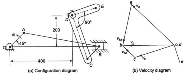
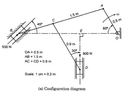
The dimensions of various links for the mechanism shown in Fig.2.26(a) are: \(O A=0.5 \mathrm{~m}, A B=1.5 \mathrm{~m}\), \(A C=C D=0.9 \mathrm{~m}\). The crank \(O A\) has uniform angular speed of \(180 \mathrm{rpm}\). Determine the velocities of sliders \(B\) and \(D\). Also calculate the turning
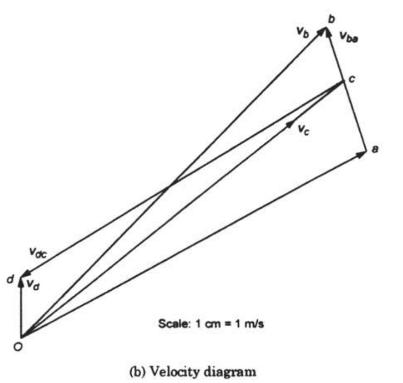
The dimensions of the various links of the mechanism shown in Fig.2.27(a) are: \(O A=50 \mathrm{~mm}\), \(A B=400 \mathrm{~mm}, B C=150 \mathrm{~mm}, C D=100 \mathrm{~mm}\), and \(D E=250 \mathrm{~mm}\). The crank \(O A\) rotates at \(60 \mathrm{rpm}\). Find velocity of slider \(E\). 30 250 OA = 50
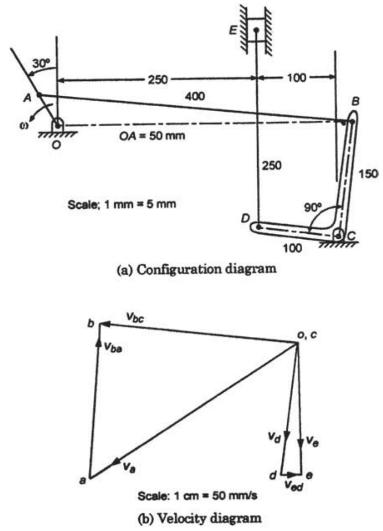
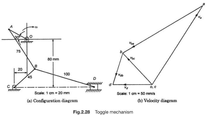
The dimensions of the various links of the mechanism shown in Fig.2.28(a) are \(\mathrm{OA}=30 \mathrm{~mm}\), \(A B=75 \mathrm{~mm}, B D=100 \mathrm{~mm}\). The crank \(O A\) rotates at \(120 \mathrm{rpm}\). Determine the velocity of the slider \(D\) and angular speed of links \(A B, B C\), and
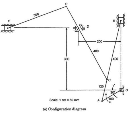
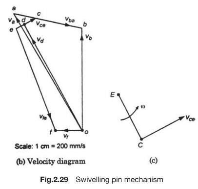
The crank \(O A\) of the mechanism shown in Fig.2.29(a) rotates at \(120 \mathrm{rpm}\). The dimensions of the various link are:\(O A=100 \mathrm{~mm}, A B=C E=400 \mathrm{~mm}, A C=125 \mathrm{~mm}\), and \(E F=300 \mathrm{~mm}\). The rod \(C E\) slides in a slot in trunnion at \(D\). Determine
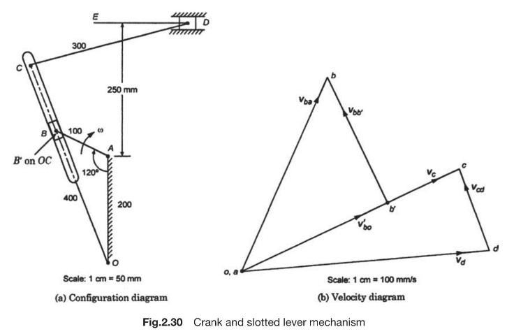
The crank and slotted lever mechanism shown in Fig.2.30(a) has the dimensions of its various links as follows:\(O A=200 \mathrm{~mm}, A B=100 \mathrm{~mm}, O C=400 \mathrm{~mm}\), and \(C D=300 \mathrm{~mm}\). The crank \(A B\) rotates at \(75 \mathrm{rpm}\). Determine (a) velocity of ram, and (b)
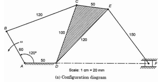
For the mechanism shown in Fig.2.31(a), determine the velocities of points \(C, E\) and \(F\). Also calculate the angular velocities of the links \(B C, C D E\), and \(E F\). Crank \(A B\) rotates at \(120 \mathrm{rpm}\). The dimensions of various links are: \(A B=60 \mathrm{~mm}, B C=120
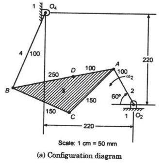
For the mechanism shown in Fig.2.32(a), determine the angular velocities of links 3 and 4 when link 2 is rotating at \(120 \mathrm{rpm}\). Also find the velocity of point \(C\) and \(D . O_{2} A=100 \mathrm{~mm}, A B=250 \mathrm{~mm}\), \(A C=150 \mathrm{~mm}, B C=150 \mathrm{~mm}, O_{4} B=100
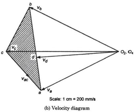
For the mechanism shown in Fig.2.33(a), determine the velocities of points \(C\) and \(A\) and angular speedy of links 3 and 4 . The link 2 rotates at \(150 \mathrm{rpm}\).\(O_{2} A=380 \mathrm{~mm}, O_{4} B=250 \mathrm{~mm}, A C=250 \mathrm{~mm}, B C=400 \mathrm{~mm}\), and \(O_{2} O_{4}=750
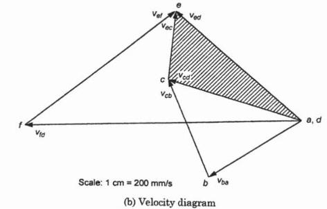
For the mechanism shown in Fig.2.34(a), determine the velocity of the slider \(C\). The link 2 rotates at \(180 \mathrm{rpm}\).\(O_{2} A=50 \mathrm{~mm}, A B=100 \mathrm{~mm}, A C=200 \mathrm{~mm}, B D=100 \mathrm{~mm}, O_{2} D=100 \mathrm{~mm}\), and \(O_{2} O_{6}=100 \mathrm{~mm}\). 2 45 6 D 5 P
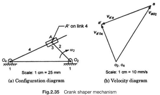
In the crank-shaper mechanism shown in Fig.2.35(a), the link 2 rotates at a constant angular speed of \(1 \mathrm{rad} / \mathrm{s}\). Determine the angular speed of link \(4, v_{A 4}, v_{A 223}\), and \(v_{A 3 A 4}, O_{2} A=50 \mathrm{~mm}, O_{4} A=80 \mathrm{~mm}\), and \(\mathrm{O}_{2}
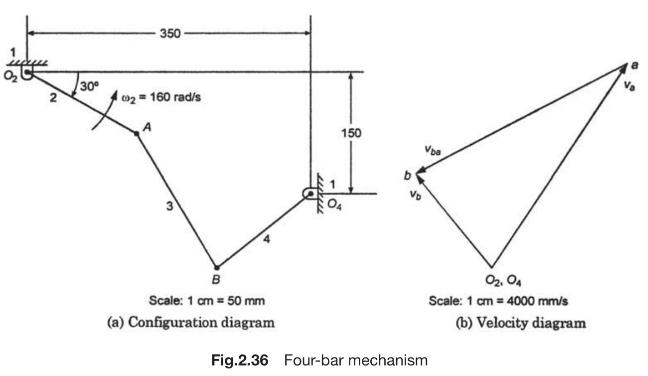
For the mechanism shown in Fig.2.36(a), the link 2 rotates at \(160 \mathrm{rad} / \mathrm{s}\). Determine \(v_{b}, \omega_{4}\) and \(v_{b a^{\prime}} O_{2} A=\) \(150 \mathrm{~mm}, A B=200 \mathrm{~mm}\), and \(O_{4} B=150 \mathrm{~mm}\). 30 2 350 002=160 rad/s 3 150 B Scale: 1 cm = 50 mm (a)
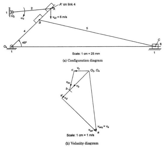
The driving link 2 of the Whitworth quick-return motion mechanism shown in Fig.2.37(a) rotates at a constant speed of \(6 \mathrm{~m} / \mathrm{s}\). Determine the velocity of tool holder. \(O_{1} \mathrm{~A}=100 \mathrm{~mm}, O_{4} \mathrm{~B}=100 \mathrm{~mm}\), \(\mathrm{BC}=300 \mathrm{~mm},
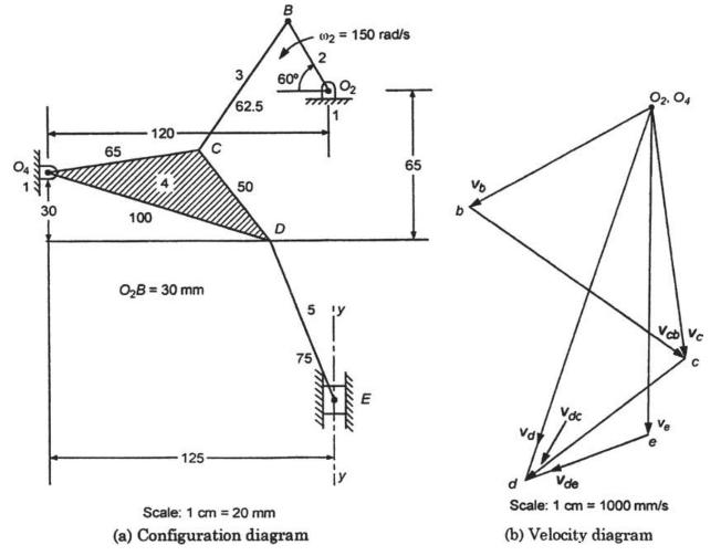
For the mechanism shown in Fig.2.38(a), determine velocity of slider and \(\omega_{3}, \omega_{4}\), and \(\omega_{5}\). WALL 65 120- 30 100 C OB = 30 mm B 002150 rad/s 2 02 65 60 62.5 125- a 50 50 Scale: 1 cm = 20 mm 5 y 75 75 www wwwwwww m b Vd 02.04 d Scale: 1 cm 1000 mm/s (a) Configuration
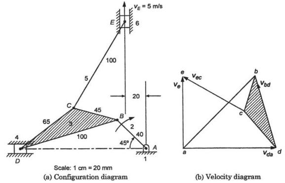
For the mechanism shown in Fig.2.39(a), \(v_{E}=5 \mathrm{~m} / \mathrm{s}\). Determine \(v_{d}\), \(\omega_{3}\), and \(\omega_{5}\). D 65 5 100 45 VE-5 m/s B 20 2 100 40 45 Scale: 1 cm = 20 mm (a) Configuration diagram Vec Vbd Vda (b) Velocity diagram
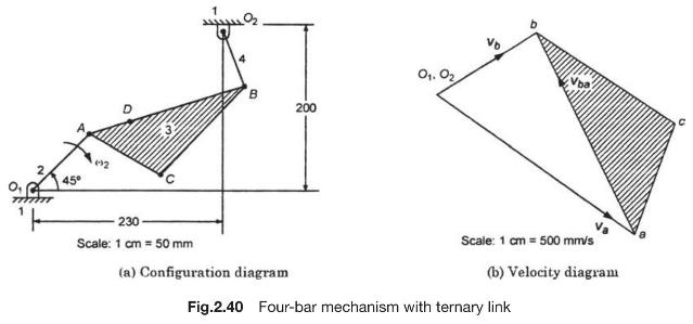
The crank \(O_{1} A\) of the four-bar linkage shown in Fig.2.40(a) is rotating at a uniform angular velocity of \(30 \mathrm{rad} / \mathrm{s}\). Draw the velocity polygon and determine the velocity of point \(B\), the angular velocities of the links 3 and 4. \(O_{1} A=100 \mathrm{~mm}, A B=200
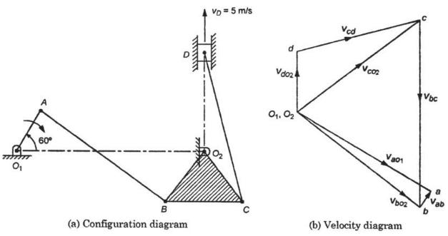
In the mechanism shown in Fig.2.41(a), the piston \(D\) moves in the vertical direction upwards with a velocity of \(5 \mathrm{~m} / \mathrm{s}\).\(O_{1} A=7.5 \mathrm{~cm}, O_{1} O_{2}=30 \mathrm{~cm}, A B=25 \mathrm{~cm}, O_{2} C=O_{2} B=10 \mathrm{~cm}, C D=25 \mathrm{~cm}\), and \(B C=12.5
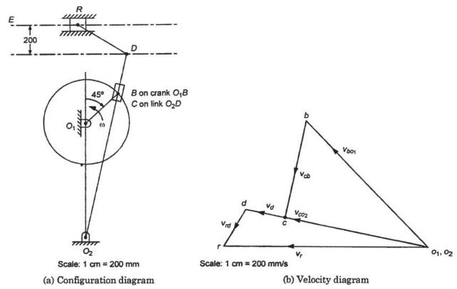
The quick-return motion mechanism of the crank and slotted lever type shaping machine is shown in Fig. \(2.42(a)\).\(O_{102}=800 \mathrm{~mm}, O_{1} B=300 \mathrm{~mm}, O_{2} D=1300 \mathrm{~mm}, D R=400 \mathrm{~mm}\).The crank \(O_{1} B\) makes and angle of \(45^{\circ}\) with the vertical and
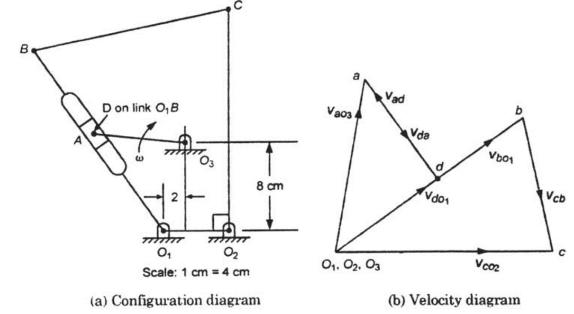
The dimesions of the mechanism shown in Fig.2.43(a) are: \(O_{1} O_{2}=6 \mathrm{~cm}, O_{3} A=8 \mathrm{~cm}, O_{1} B=20 \mathrm{~cm}\), \(B C=18 \mathrm{~cm}, O_{2} C=20 \mathrm{~cm}, \angle O_{1} O_{2} C=90^{\circ}\).The crank \(O_{3} A\) rotates uniformly at \(20 \mathrm{rad} / \mathrm{s}\)
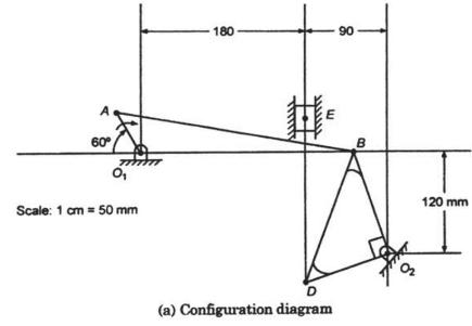
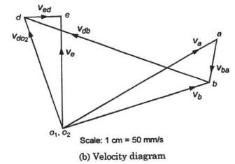
Using relative velocity method find the absolute velocity of the slider \(E\) in the mechanism shown in Fig.2.44(a). The crank \(O_{1} A\) rotates at \(60 \mathrm{rpm}\). \(O_{1} A=50 \mathrm{~mm}, O_{2} B=120 \mathrm{~mm}, A B=270 \mathrm{~mm}\) \(O_{2} D=90 \mathrm{~mm}\), and \(D E=180
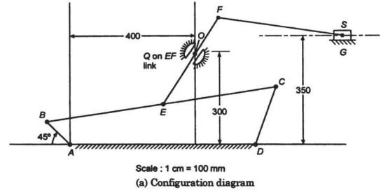
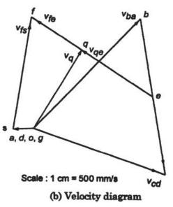
Figure 2.45(a) shows a swivelling joint mechanism in which \(A B\) is the driving crank which rotates at \(240 \mathrm{rpm}\) clockwise. 400 Q on EF link B E 300 45 D Scale: 1 cm = 100 mm (a) Configuration diagram 0 350
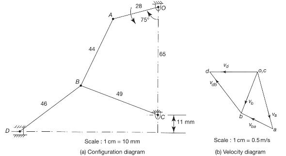
The angular velocity of crank \(O A\) shown in Fig.2.46(a) is \(600 \mathrm{rpm}\). Determine the linear velocity of slider \(D\) and the angular velocity of link \(B D\) when the crank is inclined at an angle of \(75^{\circ}\) to the vertical. The dimensions of the various links are: \(O A=28
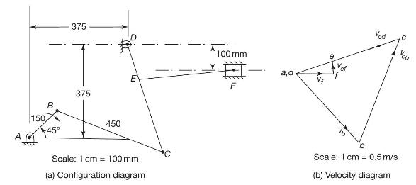
The mechanism shown in Fig. 2.47 has the dimensions of various links as follows:\[ A B=D E=150 \mathrm{~mm}, B C=C D=450 \mathrm{~mm}, E F=375 \mathrm{~mm} \]The crank \(A B\) makes an angle of \(45^{\circ}\) with the horizontal and rotates about \(A\) in the clockwise direction at a uniform speed
The dimensions of a four-bar mechanism are:\(A D=300 \mathrm{~mm}, B C=A B=360 \mathrm{~mm}, C D=600 \mathrm{~mm}\). The link \(C D\) is fixed and \(\angle A D C=60^{\circ}\). The driving link \(A D\) rotates uniformly at a speed of \(120 \mathrm{rpm}\) clockwise and the constant driving torque is
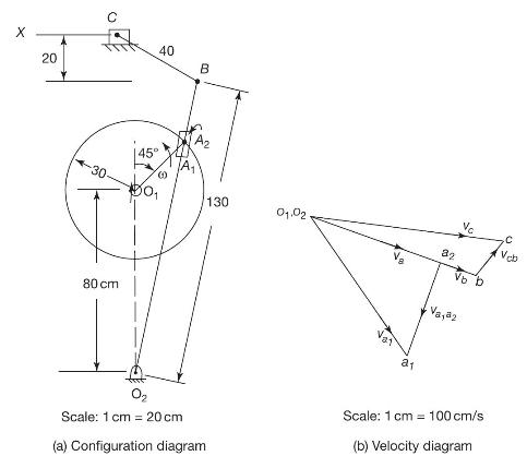
A quick-return mechanism of a shaper is shown in Fig.2.49(a). The crank \(O_{1} A\) rotates in the counterclockwise direction. Determine the linear velocity of the cutting tool when the crank \(O_{1} A\) is at \(45^{\circ}\) with the horizontal. All dimensions are given in the figure. X 40 40 20
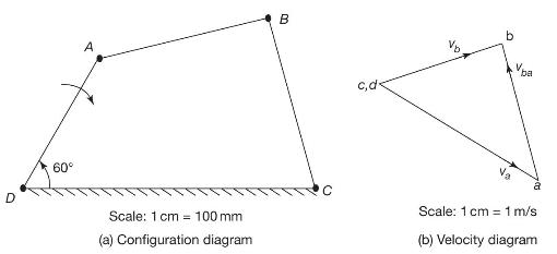
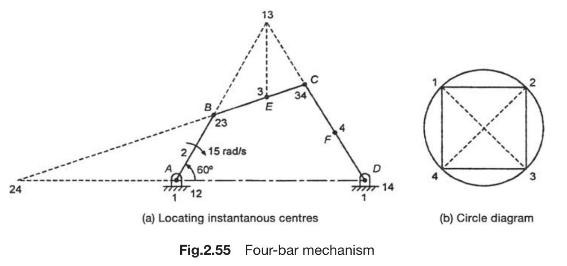
In the four-bar mechanism shown in Fig.2.55(a), link 2 is rotating at angular velocity of \(15 \mathrm{rad} / \mathrm{s} c \omega\). Locate all the instantaneous centres of the mechanism and find (a) the angular speeds of links 3 and 4, (b) the linear velocities of links 3 and 4, and (c) the linear
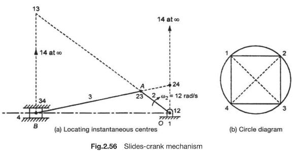
Locate the instantaneous centres of the slider crank mechanism shown in Fig.2.56(a). Find the velocity of the slider. \(O A=160 \mathrm{~mm}, A B=470 \mathrm{~mm}\), and \(O B=600 \mathrm{~mm}, \omega_{2}=12 \mathrm{rad} / \mathrm{s} \mathrm{cw}\). 13 B 14 at 3 34 14 at 24 12 rad/s 12 (a)
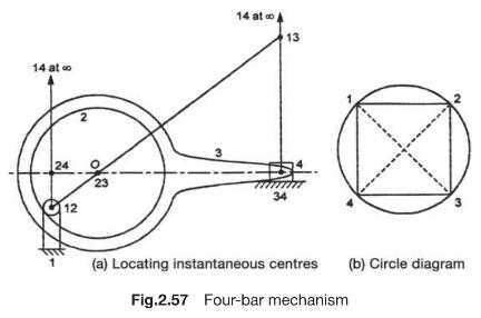
Locate the instantaneous centres of the mechanisms shown in Fig.2.57(a). 14 at 24 12 14 at A 13 34 (a) Locating instantaneous centres (b) Circle diagram Fig.2.57 Four-bar mechanism
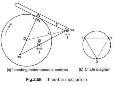
Locate the instantaneous centres of the mechanism shown in Fig.2.58. 23 P 12 13 2 12 (a) Locating instantaneous centres (b) Circle diagram Fig.2.58 Three-bar mechanism
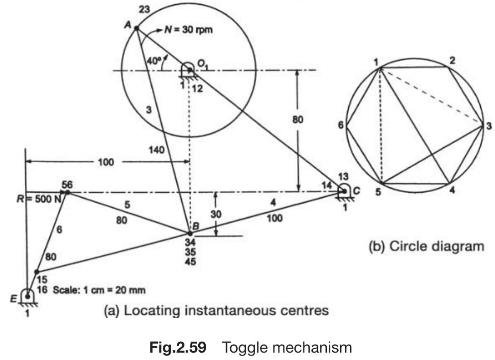
In the toggle mechanism, shown in Fig.2.59, crank \(O_{1} A\) rotates at \(30 \mathrm{rpm}\) clockwise. \(O_{1} A=40 \mathrm{~mm}\), \(A B=140 \mathrm{~mm}, B C=100 \mathrm{~mm}, B D=80 \mathrm{~mm}\), and \(D E=80 \mathrm{~mm}\). Neglecting friction and inertia effects, calculate the torque
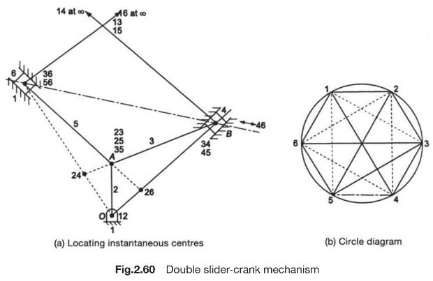
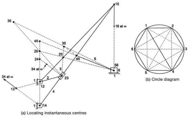
Determine all the instantaneous centres of the double slider-crank mechanism shown in Fig.2.60(a). 16 at co 14 at 13 36 56 15 222 2 3 46 012 26 (a) Locating instantaneous centres Fig.2.60 Double slider-crank mechanism (b) Circle diagram
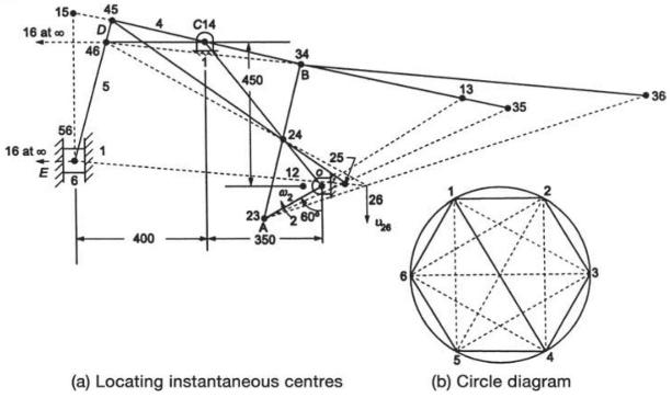
Locate all the instantaneous centres of the Whitworth mechanism shown in Fig.2.61(a). 36 34 at co 13 35 261 25 45 24 34 atico 23 114 (a) Locating instantaneous centres 15 16 at co (b) Circle diagram
Determine all the instantaneous centres of the mechanism shown in Fig.2.62(a). Calculate the velocities of the slider \(E\) and the joints \(B\) and \(D\) when the crank \(O A\) is rotating at \(120 \mathrm{rpm}\). Also find \(\omega_{A B}, \omega_{B D}\), and \(\omega_{D E} . O A=200 \mathrm{~mm},
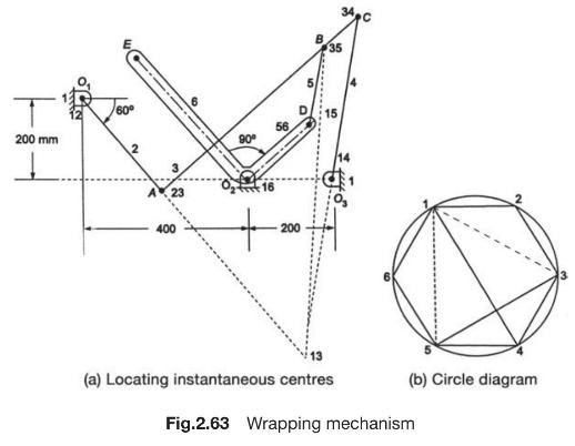
A wrapping mechanism is shown in Fig.2.63(a). The crank \(O_{1} A\) rotates at a uniform speed of 1200 \(\mathrm{rpm}\). Determine the velocity of point \(E\) on the bell crank lever.\[ \begin{aligned} & O_{1} A=300 \mathrm{~mm}, A C=650 \mathrm{~mm}, B C=100 \mathrm{~mm}, O_{3} C=400
Showing 1000 - 1100
of 1879
First
4
5
6
7
8
9
10
11
12
13
14
15
16
17
18
Last
Step by Step Answers