New Semester
Started
Get
50% OFF
Study Help!
--h --m --s
Claim Now
Question Answers
Textbooks
Find textbooks, questions and answers
Oops, something went wrong!
Change your search query and then try again
S
Books
FREE
Study Help
Expert Questions
Accounting
General Management
Mathematics
Finance
Organizational Behaviour
Law
Physics
Operating System
Management Leadership
Sociology
Programming
Marketing
Database
Computer Network
Economics
Textbooks Solutions
Accounting
Managerial Accounting
Management Leadership
Cost Accounting
Statistics
Business Law
Corporate Finance
Finance
Economics
Auditing
Tutors
Online Tutors
Find a Tutor
Hire a Tutor
Become a Tutor
AI Tutor
AI Study Planner
NEW
Sell Books
Search
Search
Sign In
Register
study help
engineering
machine elements in mechanical design
Machine Elements In Mechanical Design 6th Edition Robert Mott, Edward Vavrek, Jyhwen Wang - Solutions
Specify the required length of no. 60 chain to mount on sprockets having 15 and 50 teeth with a center distance of no more than 36 in.
For the chain specified in Problem 34, compute the actual center distance. Data in Problem 34,Specify the required length of no. 60 chain to mount on sprockets having 15 and 50 teeth with a center distance of no more than 36 in.
For the chain specified in Problem 36, compute the actual center distance. Data in Problem 36,Specify the required length of no. 40 chain to mount on sprockets having 11 and 45 teeth with a center distance of no more than 24 in.
A synchronous belt drive is to have an input sprocket rotational speed of 800 rpm and an output sprocket speed of 600 rpm.(a) List the sprocket combinations that could be used and list the pitch diameters for each sprocket. (b) For each sprocket combination from (a) and using a 1440-8MGT belt,
A synchronous belt drive is to have an input sprocket rotational speed of 1200 rpm and an output sprocket speed of 600 rpm. (a) List the sprocket combinations with an 8-mm pitch that could be used and list the pitch diameters for each sprocket. (b) For each sprocket combination from (a)
List the approximate value of Poisson’s ratio for the following materials: (a) Carbon and alloy steel; (b) Aluminum; (c) Lead; (d) Gray cast iron; (e) Concrete; (f) Elastomers.
Use the Matweb website to determine at least three appropriate materials for a shaft design. An alloy steel is preferred with a minimum yield strength of 150 ksi (1035 MPa) and a good ductility as represented by an elongation of 10% or greater.
Describe and compare the methods for measuring flexural strength and flexural modulus for rigid plastics using the 3-point bending method and the 4-point bending method.
Use the Matweb website to determine at least three appropriate plastic materials for use as a cam. The materials should have good strength properties and a high toughness.
List five kinds of wear.
Use the DuPont Plastics website to determine at least three appropriate plastic materials for use as a cam. The materials should have good strength properties and a high toughness.
Name four types of carbon and alloy steel commonly used for commercially available shapes.
Use the DuPont Plastics website to determine at least three appropriate plastic materials for use as a housing for an industrial product. Moderate strength, high rigidity, and high toughness are required.
Name two types of stainless steel commonly used for commercially available shapes.
Use the Alcoa website to determine at least three appropriate aluminum alloys for a mechanical component that requires moderate strength, good machinability, and good corrosion resistance.
Name four types of aluminum alloys commonly used for commercially available shapes.
Name three U.S. organizations whose names are commonly used in designations for steels used in machine design.
Use the Copper Development Association website to recommend at least three copper alloys for a wormgear. Good strength and ductility are desirable along with good wear properties.
Name the U.S. organization chiefly responsible for assigning aluminum alloy designations.
Use the Copper Development Association website to recommend at least three copper alloys for a bearing application. Moderate strength and good friction and wear properties are required.
A U.S. designer specifies SAE 4140 steel for a machine component. Name the alloy designation if the same component were to be produced in:(a) Germany; (b) The United Kingdom; (c) The European Union; (d) China;(e) Japan.
Locate the description of the ASTM Standard A992 structural steel that is commonly used for rolled-steel beam shapes. Determine how to acquire a copy of the standard.
List four liquid media used as quenchants during heattreating operations.
Describe the process of shot peening and the benefits of using it.
List four carbon and alloy casting steels used in general applications.
List four carbon and alloy casting steels used for parts that must sustain pressurized fluids.
Describe the cast material called CADI and list four typical applications.
Describe the cast material called white iron and list four typical applications.
Describe the press and sinter procedure for producing machine components from powder metallurgy technology.
Describe the isostatic pressing procedure for producing machine components from powder metallurgy technology.
Describe the metal injection molding procedure for producing machine components from powder metallurgy technology.
Describe the powder forging procedure for producing machine components from powder metallurgy technology.
List four carbon or alloy powdered steel designations and give their tensile strength rating in the heat-treated condition.
List powdered metal designations for the following types of metals and give their tensile strength rating: (a) Nickel silver; (b) Bronze; (c) Copper; (d) Aluminum.
State the typical limit on part size for powder metal parts?
Name at least two aluminum casting alloys in each of the series: 200, 300, 400, 500, 700, and 800.
Name three general-purpose aluminum forging alloys.
Name the most widely used zinc casting alloy and give its typical tensile strength.
Name the three widely used ZA zinc alloys and describe the significance of the A in the designation name. For each named alloy, give its typical tensile strength.
Give two major reasons for specifying nickel-based alloys for a machine component.
Specify at least one brass or bronze alloy for the following applications: (a) Bearings; (b) Gears; (c) Screw machine parts; (d) Marine hardware; (e) Pump housings; (f) Aircraft parts.
Describe the conditions for copper alloys designated by: (a) H04; (b) H02; (c) H01; (d) H08.
Describe what the temper designation TD means.
List the six general classifications of materials that designers may specify for machine components.
Give three examples of hybrid materials.
A tensile member in a machine structure is subjected to a steady load of 4.50 kN. It has a length of 750 mm and is made from a steel tube having an outside diameter of 18 mm and an inside diameter of 12 mm. Compute the tensile stress in the tube and the axial deformation.
Compute the stress in a round bar having a diameter of 10.0 mm and subjected to a direct tensile force of 3500 N.
Compute the stress in a rectangular bar having crosssectional dimensions of 10.0 mm by 30.0 mm when a direct tensile force of 20.0 kN is applied.
A link in a packaging machine mechanism has a square cross section 0.40 in on a side. It is subjected to a tensile force of 860 lb. Compute the stress in the link.
Two circular rods support the 3800 lb weight of a space heater in a warehouse. Each rod has a diameter of 0.375 in and carries 1/2 of the total load. Compute the stress in the rods.
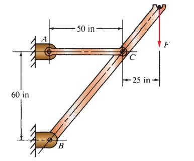
Compute the stress in the middle portion of rod AC in Figure P3–8 if the vertical force on the boom is 2500 lb. The rod is rectangular, 1.50 in by 3.50 in. Data in Figure P3–8 60 in B -50 in- C -25 in- F
A tensile load of 5.00 kN is applied to a square bar, 12 mm on a side and having a length of 1.65 m. Compute the stress and the axial deformation in the bar if it is made from (a) SAE 1020 hot-rolled steel, (b) SAE 8650 OQT 1000 steel, (c) Ductile iron A536(60-40-18), (d)
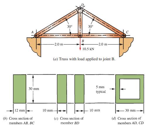
Figure P3–12 shows a small truss spanning between solid supports and suspending a 10.5 kN load. The cross sections for the three main types of truss members are shown. Compute the stresses in all of the members of the truss near their midpoints away from the connections. Consider all joints to be
An aluminum rod is made in the form of a hollow square tube, 2.25 in outside, with a wall thickness of 0.120 in. Its length is 16.0 in. What axial compressive force would cause the tube to shorten by 0.004 in? Compute the resulting compressive stress in the aluminum.
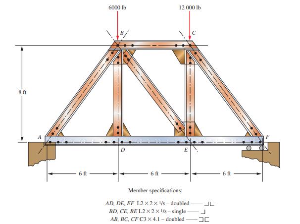
The truss shown in Figure P3–13 spans a total space of 18.0 ft and carries two concentrated loads on its top chord. The members are made from standard steel angle and channel shapes as indicated in the figure. Consider all joints to be pinned. Compute the stresses in all members near their
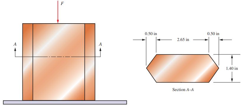
Figure P3–14 shows a short leg for a machine that carries a direct compression load. Compute the compressive stress if the cross section has the shape shown and the applied force is F = 52,000 lb.Data in Figure P3–14 F A 0.50 in 2.65 in Section A-A 0.50 in 1.40 in
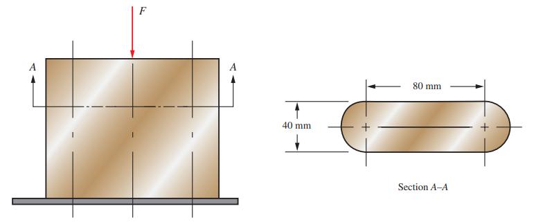
Consider the short compression member shown in Figure P3–15. Compute the compressive stress if the cross section has the shape shown and the applied load is 640 kN. Data in Figure P3–15. A F A 40 mm 80 mm Section A-A
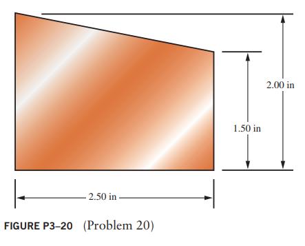
A punch is attempting to cut a slug having the shape shown in Figure P3–20 from a sheet of aluminum having a thickness of 0.060 in. Compute the shearing stress in the aluminum when a force of 52 000 lb is applied by the punch. -2.50 in FIGURE P3-20 (Problem 20) 1.50 in 2.00 in
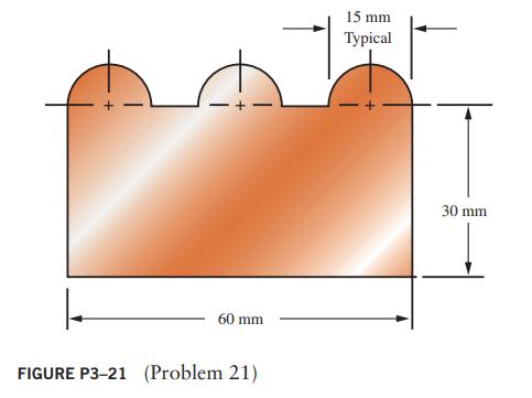
Figure P3–21 shows the shape of a slug that is to be cut from a sheet of steel having a thickness of 2.0 mm. If the punch exerts a force of 225 kN, compute the shearing stress in the steel. 60 mm FIGURE P3-21 (Problem 21) 15 mm Typical 30 mm
Compute the torsional shear stress in a circular shaft with a diameter of 50 mm that is subjected to a torque of 800 N • m.
Compute the torsional shear stress in a solid circular shaft having a diameter of 1.25 in that is transmitting 110 hp at a speed of 560 rpm.
Compute the angle of twist for the hollow shaft of Problem 26 over a length of 400 mm. The shaft is steel.Data from problem 26Compute the torsional shear stress in a hollow shaft with an outside diameter of 40 mm and an inside diameter of 30 mm when transmitting 28 kilowatts (kW) of power at a
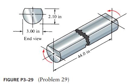
A 3.00 in-diameter steel bar has a flat milled on one side, as shown in Figure P3–29. If the shaft is 44.0 in long and carries a torque of 10 600 lb •in, compute the stress and the angle of twist. € 3.00 in End view 2.10 in FIGURE P3-29 (Problem 29) Matyl 44.0 in-
A commercial steel supplier lists rectangular steel tubing having outside dimensions of 4.00 by 2.00 in and a wall thickness of 0.109 in. Compute the maximum torque that can be applied to such a tube if the shear stress is to be limited to 6000 psi. For this torque, compute the angle of twist of
A beam is simply supported and carries the load shown in Figure P3–31. Specify suitable dimensions for the beam if it is steel and the stress is limited to 18 000 psi, for the following shapes: Data in Figure P3-31(a) Square. (b) Rectangle with height three times the width. (c) Rectangle with
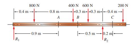
For the beam loading of Figure P3–34, draw the complete shearing force and bending moment diagrams, and determine the bending moments at points A, B, and C. Data in Figure P3–34, -0.4 m R₁ 800 N -0.9 m 0.8 m- A 400 N 600 N -0.3 m--0.3 m--0.4 m- 0.3 m-0.4 B C -0.5 m -0.5 m 200 N 0.2 m R₂
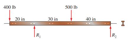
Select an aluminum I-beam shape to carry the load shown in Figure P3–37 with a maximum stress of 12 000 psi. Then compute the deflection at each load. Data in Figure P3–37 400 lb 20 in R₁ 30 in 500 lb 40 in R₁₂ I
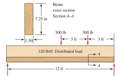
Figure P3–38 represents a wood joist for a platform, carrying a uniformly distributed load of 120 lb/ft and two concentrated loads applied by some machinery. Compute the maximum stress due to bending in the joist and the maximum vertical shear stress.Data in Figure P3–38 1.50 7.25
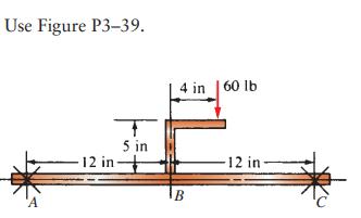
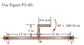
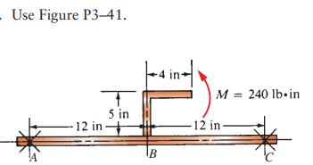
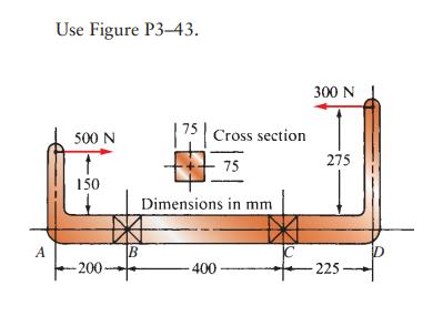
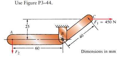
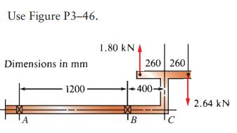
Draw the free-body diagram of only the horizontal beam portion of the given figures. Then draw the complete shear and bending moment diagrams. Where used, the symbol X indicates a simple support capable of exerting a reaction force in any direction but having no moment resistance. For beams having
Draw the free-body diagram of only the horizontal beam portion of the given figures. Then draw the complete shear and bending moment diagrams. Where used, the symbol X indicates a simple support capable of exerting a reaction force in any direction but having no moment resistance. For beams having
Draw the free-body diagram of only the horizontal beam portion of the given figures. Then draw the complete shear and bending moment diagrams. Where used, the symbol X indicates a simple support capable of exerting a reaction force in any direction but having no moment resistance. For beams having
Draw the free-body diagram of only the horizontal beam portion of the given figures. Then draw the complete shear and bending moment diagrams. Where used, the symbol X indicates a simple support capable of exerting a reaction force in any direction but having no moment resistance. For beams having
Draw the free-body diagram of only the horizontal beam portion of the given figures. Then draw the complete shear and bending moment diagrams. Where used, the symbol X indicates a simple support capable of exerting a reaction force in any direction but having no moment resistance. For beams having
Draw the free-body diagram of only the horizontal beam portion of the given figures. Then draw the complete shear and bending moment diagrams. Where used, the symbol X indicates a simple support capable of exerting a reaction force in any direction but having no moment resistance. For beams having
Draw the free-body diagram of only the horizontal beam portion of the given figures. Then draw the complete shear and bending moment diagrams. Where used, the symbol X indicates a simple support capable of exerting a reaction force in any direction but having no moment resistance. For beams having
Draw the free-body diagram of only the horizontal beam portion of the given figures. Then draw the complete shear and bending moment diagrams. Where used, the symbol X indicates a simple support capable of exerting a reaction force in any direction but having no moment resistance. For beams having
Draw the free-body diagram of only the horizontal beam portion of the given figures. Then draw the complete shear and bending moment diagrams. Where used, the symbol X indicates a simple support capable of exerting a reaction force in any direction but having no moment resistance. For beams having
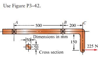
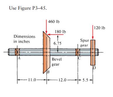
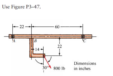
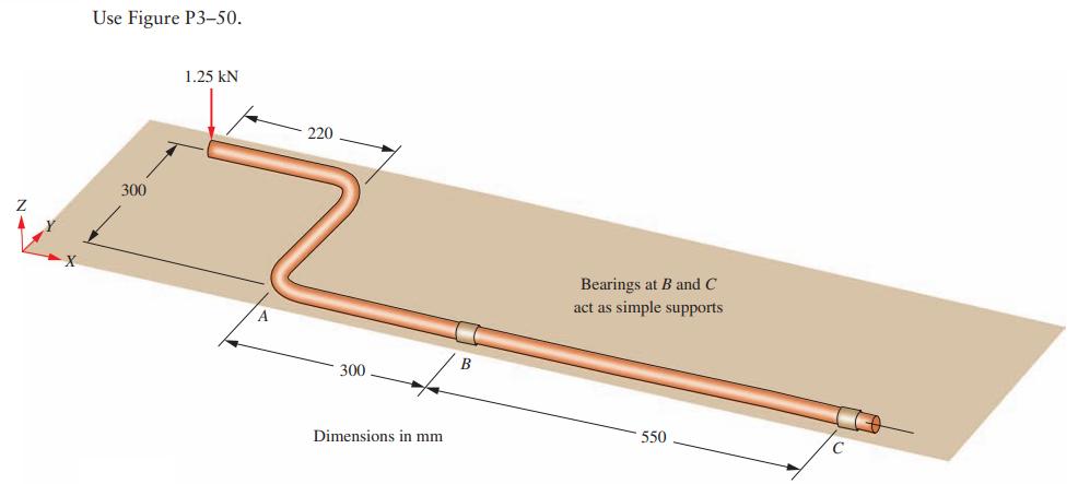
Draw the free-body diagram of the main shaft portion, labeled A, B, and C. Include any unbalanced torque on the shaft that tends to rotate it about the z-axis. In each case, the reaction to the unbalanced torque is taken at the right end of the shaft labeled C. Then draw the complete shearing force
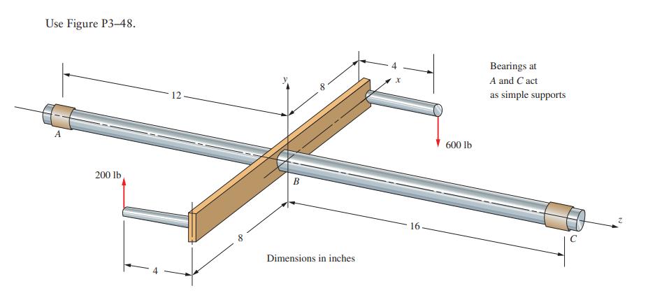
Draw the free-body diagram of the main shaft portion, labeled A, B, and C. Include any unbalanced torque on the shaft that tends to rotate it about the z-axis. In each case, the reaction to the unbalanced torque is taken at the right end of the shaft labeled C. Then draw the complete shearing force
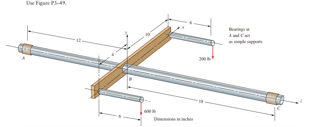
Draw the free-body diagram of the main shaft portion, labeled A, B, and C. Include any unbalanced torque on the shaft that tends to rotate it about the z-axis. In each case, the reaction to the unbalanced torque is taken at the right end of the shaft labeled C. Then draw the complete shearing force
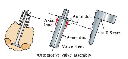
Figure P3–61 shows a valve stem from an engine subjected to an axial tensile load applied by the valve spring. For a force of 1.25 kN, compute the maximum stress at the fillet under the shoulder. Data in Figure P3–61 ARAME Axial load 9-mm dia.. 6-mm dia. Valve stem Automotive valve assembly r
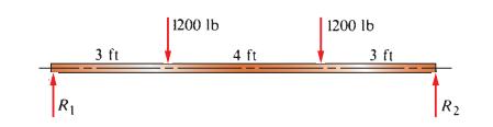
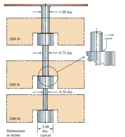
The conveyor fixture shown in Figure P3–62 carries three heavy assemblies (1200 lb each). Compute the maximum stress in the fixture, considering stress concentrations at the fillets and assuming that the load acts axially. Data in Figure P3–62 1200 lb 1200 lb 1200 lb Dimensions in
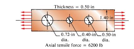
For the flat plate in tension in Figure P3–63, compute the stress at each hole, assuming that the holes are sufficiently far apart that their effects do not interact. Data in Figure P3–63 Thickness=0.50 in 0.72-in dia. Axial tensile force 0.40-in dia. 1.40 in 0.50-in dia. 6200 lb
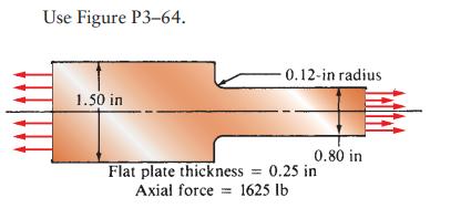
Compute the maximum stress in the member, considering stress concentrations. Use Figure P3-64. 1.50 in Flat plate thickness Axial force -0.12-in radius 0.80 in 0.25 in 1625 lb
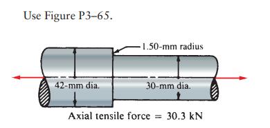
Compute the maximum stress in the member, considering stress concentrations. Use Figure P3-65. 42-mm dia. -1.50-mm radius 30-mm dia. Axial tensile force = 30.3 kN
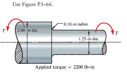
Compute the maximum stress in the member, considering stress concentrations. T Use Figure P3-66. 2.00-in dia. -0.10-in radius 1.25-in dia. Applied torque = 2200 lb in T
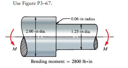
Compute the maximum stress in the member, considering stress concentrations. Use Figure P3-67. M 2.00-in dia. Bending moment -0.06-in radius = 1.25-in dia. 2800 lb in M
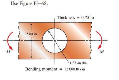
Compute the maximum stress in the member, considering stress concentrations. M Use Figure P3-68. 2.00 in Thickness=0.75 in 1.38-in dia. Bending moment = 12 000 lb-in M
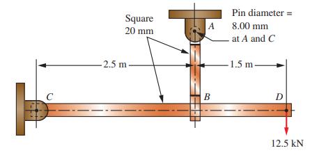
Figure P3–69 Shows a horizontal beam supported by a vertical tension link. The cross sections of both the beam and the link are 20 mm square. All connections use 8.00 mm-diameter cylindrical pins in double shear. Compute the tensile stress in member A-B, the stress due to bending in C-D, and the
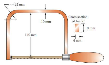
A coping saw frame shown in Figure P3–82 is made from SAE 1020 CD steel. A screw thread in the handle draws the blade of the saw into a tension of 120 N. Determine the resulting design factor based on yield strength in the area of the corner radii of the frame. Data in Figure P3–82 - r = 22
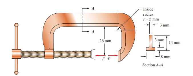
The C-clamp in Figure P3–86 is made of cast zinc, ZA12. Determine the force that the clamp can exert for a design factor of 3 based on ultimate strength in either tension or compression.Data in Figure P3–86 A A C 26 mm FF Inside radius r = 5 mm 3 mm 3 mm 14 mm 8 mm Section A-A
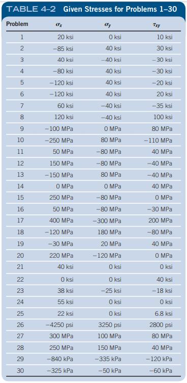
For the sets of given stresses on an element given in Table 4–2, draw a complete Mohr’s circle, find the principal stresses and the maximum shear stress, and draw the principal stress element and the maximum shear stress element. Any stress components not shown are assumed to be zero. Refer to
Write a set of functions and design requirements in:The hood latch for an automobile.
Write a set of functions and design requirements in:A portable crane to be used in small garages and homes.
Write a set of functions and design requirements in:A machine to crush soft-drink or beer cans.
Write a set of functions and design requirements in:An automatic transfer device for a production line.
Write a set of functions and design requirements in:A device to raise a 55-gallon (gal) drum of bulk materials and dump the contents into a hopper.
Write a set of functions and design requirements in:A paper feed device for a copier.
Write a set of functions and design requirements in:A crane to lift building materials from the ground to the top of a building during construction.
Write a set of functions and design requirements in:A machine to insert toothpaste tubes into cartons.
Showing 1700 - 1800
of 1879
First
5
6
7
8
9
10
11
12
13
14
15
16
17
18
19
Step by Step Answers