New Semester
Started
Get
50% OFF
Study Help!
--h --m --s
Claim Now
Question Answers
Textbooks
Find textbooks, questions and answers
Oops, something went wrong!
Change your search query and then try again
S
Books
FREE
Study Help
Expert Questions
Accounting
General Management
Mathematics
Finance
Organizational Behaviour
Law
Physics
Operating System
Management Leadership
Sociology
Programming
Marketing
Database
Computer Network
Economics
Textbooks Solutions
Accounting
Managerial Accounting
Management Leadership
Cost Accounting
Statistics
Business Law
Corporate Finance
Finance
Economics
Auditing
Tutors
Online Tutors
Find a Tutor
Hire a Tutor
Become a Tutor
AI Tutor
AI Study Planner
NEW
Sell Books
Search
Search
Sign In
Register
study help
sciences
applied fluid mechanics
Chemical Engineering Fluid Mechanics 3rd Edition Ron Darby, Raj P Chhabra - Solutions
A nozzle with a $1 \mathrm{in}$. ID outlet is attached to a $3 \mathrm{in}$. ID fire hose. Water pressure inside the hose is $100 \mathrm{psig}$ and the flow rate is $100 \mathrm{gpm}$. Calculate the force (magnitude and direction) required to hold the nozzle at an angle of $45^{\circ}$ relative to
Water flows through a $45^{\circ}$ expansion pipe bend at a rate of $200 \mathrm{gpm}$, exiting into the atmosphere. The inlet to the bend is $2 \mathrm{in}$. ID, the exit is $3 \mathrm{in}$. ID, and the loss coefficient for the bend is 0.3 based on the inlet velocity. Calculate the force
A patrol boat is powered by a water jet engine, which takes water in at the bow through a $1 \mathrm{ft}$ diameter duct and pumps it out the stern through a 3 in. diameter exhaust jet. If the water is pumped at a rate of $5000 \mathrm{gpm}$, determine(a) The thrust rating of the engine(b) The
A patrol boat is powered by a water jet pump engine. The engine takes water in through a $3 \mathrm{ft}$ diameter duct in the bow and discharges it through a $1 \mathrm{ft}$ diameter duct in the stern. The drag coefficient of the boat has a value of 0.1 based on a total underwater area of $1500
Water is flowing through a $45^{\circ}$ pipe bend at a rate of $200 \mathrm{gpm}$ and exits into the atmosphere. The inlet to the bend is $1 \frac{1}{2} \mathrm{in}$. inside diameter, and the exit is $1 \mathrm{in}$. in diameter. The friction loss in the bend can be characterized by a loss
The arms of a lawn sprinkler are 8 in. long and $3 / 8$ in. ID. Nozzles at the end of each arm direct the water in a direction that is $45^{\circ}$ from the arms. If the total flow rate is $10 \mathrm{gpm}$, determine:(a) The moment developed by the sprinkler if it is held stationary and not
A water sprinkler contains two $1 / 4 \mathrm{in}$. ID jets at the ends of a rotating hollow ( $3 / 8 \mathrm{in}$. ID) tube, which direct the water $90^{\circ}$ to the axis of the tube. If the water leaves at $20 \mathrm{ft} / \mathrm{s}$, what torque would be necessary to hold the sprinkler in
An open container $8 \mathrm{in}$. high with an inside diameter of $4 \mathrm{in}$. weighs $5 \mathrm{lb}_{\mathrm{f}}$ when empty. The container is placed on a scale and water flows into the top of the container through a $1 \mathrm{in}$. diameter tube at a rate of $40 \mathrm{gpm}$. The water
A boat is tied to a dock by a line from the stern of the boat to the dock. A pump inside the boat takes water in through the bow and discharges it out the stern at a rate of $3 \mathrm{ft}^{3} / \mathrm{s}$ through a pipe running through the hull. The pipe inside area is $0.25 \mathrm{ft}^{2}$ at
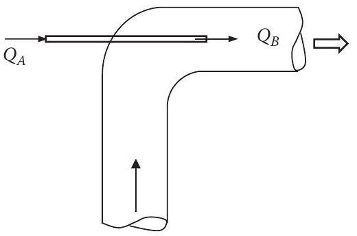
A jet ejector pump is shown in Figure P5.61. A high-speed stream $\left(Q_{A}\right)$ is injected at a rate of $50 \mathrm{gpm}$ through a small tube $1 \mathrm{in}$. in diameter, into a stream $\left(Q_{B}\right)$ in a larger, $3 \mathrm{in}$. diameter, tube. The energy and momentum are
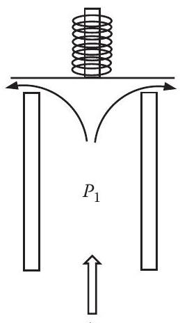
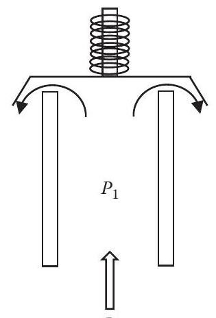
Figure P5.62 illustrates two relief valves. The valve disk is designed to lift when the upstream pressure in the vessel $\left(P_{1}\right)$ reaches the valve set pressure. Valve $\mathrm{A}$ has a disk that diverts the fluid leaving the valve by $90^{\circ}$ (i.e., to the horizontal direction),
A relief valve is mounted on top of a large vessel containing hot water. The inlet diameter to the valve is 4 in., and the outlet diameter is 6 in. The valve is set to open when the pressure in the vessel reaches $100 \mathrm{psig}$, which happens when the water is at $200^{\circ} \mathrm{F}$. The
A relief valve is installed on the bottom of a pressure vessel. The entrance to the valve is $4.5 \mathrm{in}$. diameter and the exit (which discharges in the horizontal direction, $90^{\circ}$ from the entrance) is 5 in. diameter. The loss coefficient for the valve is 4.5 based on the inlet
An emergency relief valve is installed on a reactor to relieve excess pressure in case of a runaway reaction. The lines upstream and downstream of the valve are 6 in. sch 40 pipe. The valve is designed to open when the tank pressure reaches $100 \mathrm{psig}$, and the vent exhausts to the
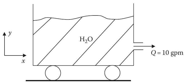
Consider the "tank on wheels" shown in Figure P5.66. Water is draining out of a hole in the side of the open tank, at a rate of $10 \mathrm{gpm}$. If the tank diameter is $2 \mathrm{ft}$ and the diameter of the hole is 2 in., determine the magnitude and direction of the force transmitted from the
The tank in Problem 66 is 6 in. in diameter and contains water at a depth of $3 \mathrm{ft}$. On the side of the tank near the bottom is a $1.5 \mathrm{in}$. ID outlet to which is attached a ball valve, which has a loss coefficient of 1.2. When the valve is opened, the water flows out in a
Use the microscopic equations of motion in Appendix $\mathrm{E}$ as a starting point to derive a relationship between the volumetric flow rate and the pressure gradient for a Newtonian fluid in a pipe that is valid for any orientation of the pipe axis. the critical starting point requires that you
A viscous molten polymer is pumped through a thin slit between two flat surfaces. The slit has a depth $H$, width $W$, and length $L$, and is inclined upward at an angle $\theta$ to the horizontal $(H \ll W)$. The flow is laminar, and the polymer is non-Newtonian, with properties that can be
Acrylic latex paint can be described as a Bingham plastic with a yield stress of $200 \mathrm{dyn} / \mathrm{cm}^{2}$, a limiting viscosity of $50 \mathrm{cP}$, and a density of $0.95 \mathrm{~g} / \mathrm{cm}^{3}$.(a) What is the maximum thickness at which a film of this paint could be spread on a
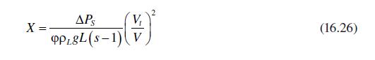
A vertical belt is moving upward continuously through a liquid bath at a velocity $V$. A film of the liquid adheres to the belt, which tends to drain downward due to gravity. The equilibrium thickness of the film is determined by the steady-state condition at which the downward drainage velocity of
Water at $70^{\circ} \mathrm{F}$ flows upward through a vertical tube and overflows over the top and down the outside wall. The OD of the tube is 4 in., and the water flow rate is $1 \mathrm{gpm}$. Determine the thickness of the film. Is the flow laminar or turbulent?
For laminar flow of a Newtonian fluid in a tube(a) Show that the average velocity over the cross section is half of the maximum velocity in the tube.(b) Derive the kinetic energy correction factor for laminar flow of a Newtonian fluid in a tube (i.e., $\alpha=2$ ).
A slider bearing can be described as one plate moving with a velocity $V$ parallel to a stationary plate, with a viscous lubricant in between the plates. The force applied to the moving plate is $F$, and the distance between the plates is $H$. If the lubricant is a grease with properties that can
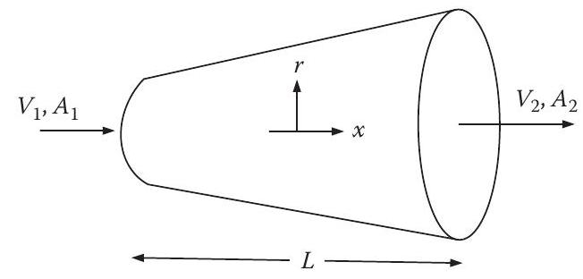
Consider a fluid flowing in a conical section, as illustrated in Figure P5.75. The mass flow rate is the same going in (through point 1) as it is coming out (point 2), but the velocity changes because the area changes. They are related by\[(ho V A)_{1}=(ho V A)_{2}\]FIGURE P5.75 Flow in a
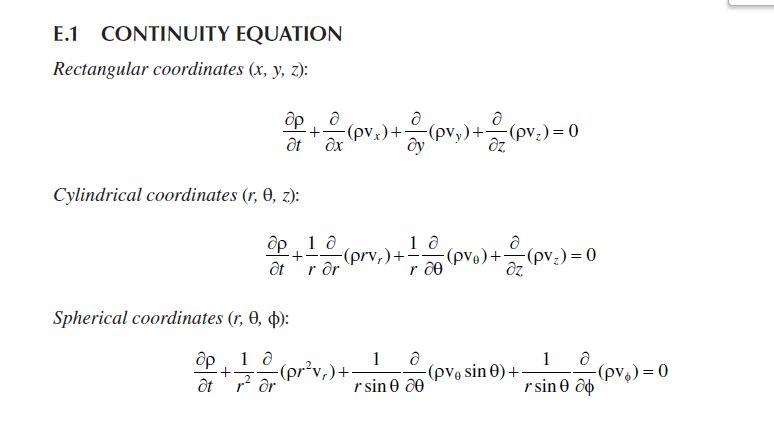
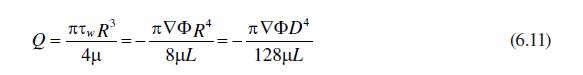
Show how the Hagen-Poiseuille equation for the steady laminar flow of a Newtonian fluid in a uniform cylindrical tube can be derived starting from the general microscopic equations of motion (e.g., the continuity and momentum equations given in Appendix E).Appendix E). E.1 CONTINUITY EQUATION
The Hagen-Poiseuille equation (Equation 6.11) describes the laminar flow of a Newtonian fluid in a tube. Since a Newtonian fluid is defined by the relation $\tau=\mu \dot{\gamma}$, rearrange the HagenPoiseuille equation to show that the shear rate at the tube wall for a Newtonian fluid is given by
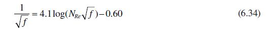
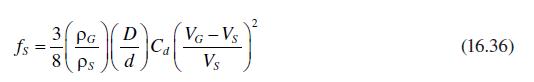
Derive the relation between the friction factor and Reynolds number in turbulent flow for smooth pipe (Equation 6.34), starting with the von Karman equation for the velocity distribution in the turbulent boundary layer (Equation 6.26). 4. 4.1log(Ne)-0.60 (6.34)
Evaluate the kinetic energy correction factor $\alpha$ in the Bernoulli equation for turbulent flow assuming the $1 / 7$ power law velocity profile (Equation 6.36) is valid. Repeat this for laminar flow of a Newtonian fluid in a tube, for which the velocity profile is parabolic. fs 2 3 PG D = Cd
A Newtonian fluid with $\mathrm{SG}=0.8$ is forced through a capillary tube at a rate of $5 \mathrm{~cm}^{3} / \mathrm{min}$. The tube has a downward slope of $30^{\circ}$ to the horizontal, and the pressure drop is measured between two taps located $40 \mathrm{~cm}$ apart on the tube using a
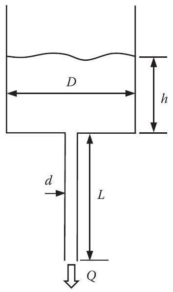
A liquid is draining from a cylindrical vessel through a tube in the bottom of the vessel, as illustrated in Figure P6.6 below. If the liquid has a specific gravity of 0.85 and drains out at a rate of $1 \mathrm{~cm}^{3} / \mathrm{s}$, what is the viscosity of the liquid? The entrance loss
Repeat problem 7 accounting for the friction loss from the vessel to the tube, assuming a loss coefficient of 0.50 at the contraction.problem 7,You are given a liquid and are asked to find its viscosity. Its density is known to be $0.97 \mathrm{~g} / \mathrm{cm}^{3}$. You place the fluid in an open
You must measure the viscosity of an oil that has an SG of 0.92 . To do this, you put the oil into a large container to the bottom of which a small vertical tube, $25 \mathrm{~cm}$ long, has been attached through which the oil can drain by gravity (see Figure P6.6). When the level of the oil in the
You want to transfer No. 3 fuel oil $\left(30^{\circ} \mathrm{API}\right)$ from a storage tank to a power plant at a rate of $2000 \mathrm{bbl} / \mathrm{day}$. The diameter of the pipeline is $1 \frac{1}{2} \mathrm{in}$. sch 40 , with a length of $1200 \mathrm{ft}$. The discharge of the line is
You must specify a pump to deliver $800 \mathrm{bbl} /$ day of a $35^{\circ} \mathrm{API}$ distillate at $90^{\circ} \mathrm{F}$ from a distillation column to a storage tank in a refinery. If the level in the tank is $20 \mathrm{ft}$ above that in the column, the total equivalent length of pipe is
Water is flowing at a rate of $700 \mathrm{gpm}$ through a horizontal 6 in. sch 80 commercial steel pipe at $90^{\circ} \mathrm{F}$. If the pressure drops by 2.23 psi over a $100 \mathrm{ft}$ length of pipe, determine the following:(a) What is the value of the Reynolds number?(b) What is the
A $35^{\circ}$ API distillate at $60^{\circ} \mathrm{F}$ is to be pumped over a distance of $2000 \mathrm{ft}$ through a $4 \mathrm{in}$. sch 40 horizontal pipeline at a flow rate of $500 \mathrm{gpm}$. What power must the pump deliver to the fluid if the pipeline is made of (a) drawn tubing, (b)
The Moody diagram illustrates the effect of roughness on the friction factor in turbulent flow but indicates no effect of roughness in laminar flow. Explain why this is so. Are there any restrictions or limitations that should be placed on this conclusion? Explain.
You have a large supply of very rusty $2 \mathrm{in}$. sch 40 steel pipe, which you want to use for a pipeline. Because rusty metal is rougher than clean metal, you want to know its effective roughness before laying the pipeline. To do this, you pump water at a rate of $100 \mathrm{gpm}$ through a
A $32 \mathrm{hp}$ pump ( $100 %$ efficient) is required to pump water through a 2 in. sch 40 pipeline, $6000 \mathrm{ft}$ long, at a rate of $100 \mathrm{gpm}$.(a) What is the equivalent roughness of the pipe?(b) If the pipeline is replaced by new commercial steel $2 \mathrm{in}$. sch 40 pipe,
You have a piping system in your plant that has gotten old and rusty. The pipe is $2 \mathrm{in}$. sch 40 steel, $6000 \mathrm{ft}$ long. You find that it takes $35 \mathrm{hp}$ to pump water through the system at a rate of $100 \mathrm{gpm}$.(a) What is the equivalent roughness of the pipe?(b) If
Water enters a horizontal tube through a flexible vertical rubber hose that can support no forces. If the tube is $1 / 8 \mathrm{in}$. sch $40,10 \mathrm{ft}$ long, and the water flow rate is $2 \mathrm{gpm}$, what force (magnitude and direction) must be applied to the tube to keep it stationary?
A water tower that is $90 \mathrm{ft}$ high provides water to a residential subdivision. The water main from the tower to the subdivision is $6 \mathrm{in}$. sch 40 steel, 3 miles long. If each house uses a maximum of $50 \mathrm{gal} / \mathrm{h}$ (at peak demand) and the pressure in the water
A heavy oil $(\mu=100 \mathrm{cP}, \mathrm{SG}=0.85)$ is draining from a large tank through a $1 / 8 \mathrm{in}$. sch 40 tube into an open bucket. The level in the tank is $3 \mathrm{ft}$ above the tube inlet, and the pressure in the tank is $10 \mathrm{psig}$. The tube is $30 \mathrm{ft}$ long,
SAE 10 lube oil $(\mathrm{SG}=0.93)$ is being pumped upward through a straight $1 / 4 \mathrm{in}$. sch 80 pipe that is oriented at $45^{\circ}$ angle to the horizontal. The two legs of a manometer using water as the manometer fluid are attached to taps in the pipe wall that are $2 \mathrm{ft}$
Cooling water is fed by gravity from an open storage tank $20 \mathrm{ft}$ above ground, through $100 \mathrm{ft}$ of $1 \frac{1}{2}$ in. ID steel pipe, to a heat exchanger at ground level. If the pressure entering the heat exchanger must be 5 psig for it to operate properly, what is the water flow
A water main is to be laid to supply water to a subdivision located 2 miles from a water tower. The water in the tower is $150 \mathrm{ft}$ above ground, and the subdivision consumes a maximum of $10,000 \mathrm{gpm}$ of water. What size pipe should be used for the water main? Assume Schedule 40
A water main is to be laid from a water tower to a subdivision that is 2 miles away. The water level in the tower is $150 \mathrm{ft}$ above the ground. The main must supply a maximum of $1000 \mathrm{gpm}$ with a minimum of $5 \mathrm{psig}$ at the discharge end, at a temperature of $65^{\circ}
The water level in a water tower is $110 \mathrm{ft}$ above ground level. The tower supplies water to a subdivision, 3 miles away, through an 8 in. sch 40 steel water main. If the minimum water pressure entering the residential water lines at the houses must be $15 \mathrm{psig}$, what is the
A hydraulic press is powered by a remote high-pressure pump. The gage pressure at the pump is $20 \mathrm{MPa}$, and the pressure required to operate the press is $19 \mathrm{MPa}$ (gage) at a flow rate of $0.032 \mathrm{~m}^{3} / \mathrm{min}$. The press and pump are to be connected by $50
Water is to be pumped at a rate of $100 \mathrm{gpm}$ from a well that is $100 \mathrm{ft}$ deep, through 2 miles of horizontal 4 in. sch 40 steel pipe, to a water tower that is $150 \mathrm{ft} \mathrm{high}$.(a) Neglecting fitting losses, what horsepower will the pump require if it is $60 %$
A concrete pipe storm sewer, $4 \mathrm{ft}$ in diameter, drops $3 \mathrm{ft}$ in elevation per mile of length. What is the maximum capacity of the sewer (in gpm) when it is flowing full?
You want to siphon water from an open tank using a 1/4 in. diameter hose. The discharge end of the hose is $10 \mathrm{ft}$ below the water level in the tank, and the siphon will not operate if the pressure falls below 1 psia anywhere in the hose. If you want to siphon the water at a rate of $1
Equation 6.43 describes the laminar flow of a power law fluid in a tube. Since a power law fluid is defined by the relation $\tau=m \dot{\gamma}^{n}$, rearrange Equation 6.43 to show that the shear rate at the tube wall for a power law fluid is given by $\dot{\gamma}_{w}=(8 V / D)(3 n+1) / 4 n$
A large tank contains SAE 10 lube oil at a temperature of $60^{\circ} \mathrm{F}$ and a pressure of $2 \mathrm{psig}$. The oil is $2 \mathrm{ft}$ deep in the tank and drains out through a vertical tube in the bottom. The tube is $10 \mathrm{ft}$ long and discharges the oil at atmospheric pressure.
A polymer solution is to be pumped at a rate of $3 \mathrm{gpm}$ through a horizontal $1 \mathrm{in}$. diameter pipe. The solution behaves as a power law fluid with a flow index of 0.5 , an apparent viscosity of $400 \mathrm{cP}$ at a shear rate of $1 \mathrm{~s}^{-1}$, and a density of $60
A coal slurry that is characterized as a power law fluid has a flow index of 0.4 and an apparent viscosity of $200 \mathrm{cP}$ at a shear rate of $1 \mathrm{~s}^{-1}$. If the coal has a specific gravity of 2.5 and the slurry is $50 %$ coal by weight in water, what pump horsepower will be required
A coal slurry is found to behave as a power law fluid, with a flow index of 0.3 , a specific gravity of 1.5 , and an apparent viscosity of $70 \mathrm{cP}$ at a shear rate of $100 \mathrm{~s}^{-1}$. What volumetric flow rate of this fluid would be required to reach turbulent flow in a 1/2 in. ID
A coal slurry is to be transported by pipeline. It has been determined that the slurry may be described by the power law model, with a flow index of 0.4 , an apparent viscosity of $50 \mathrm{cP}$ at a shear rate of $100 \mathrm{~s}^{-1}$, and a density of $90 \mathrm{lb}_{\mathrm{m}} /
A sewage sludge is to be transported a distance of $3 \mathrm{mi}$ through a $12 \mathrm{in}$. ID pipeline at a rate of $2000 \mathrm{gpm}$. The sludge is a Bingham plastic with a yield stress of $35 \mathrm{dyn} / \mathrm{cm}^{2}$, a limiting viscosity of $80 \mathrm{cP}$, and a specific gravity
A coal suspension is found to behave as a power law fluid, with a flow index of 0.4 , a specific gravity of 1.5 , and an apparent viscosity of $90 \mathrm{cP}$ at a shear rate of $100 \mathrm{~s}^{-1}$. What would the volumetric flow rate of this suspension be in a $15 \mathrm{ft}$ long, 5/8 in. ID
A coal-water slurry containing $65 %$ (by weight) coal is pumped from a storage tank at a rate of $15 \mathrm{gpm}$ through a $50 \mathrm{~m}$ long $1 / 2 \mathrm{in}$. sch 40 pipeline to a boiler where it is burned. The storage tank is at $1 \mathrm{~atm}$ pressure and $80^{\circ} \mathrm{F}$, and
A sludge is to be transported by pipeline. It has been determined that the sludge may be described by the power law model, with a flow index of 0.6 , an apparent viscosity of $50 \mathrm{cP}$ at a shear rate of $1 \mathrm{~s}^{-1}$, and a density of $95 \mathrm{lb}_{\mathrm{m}} / \mathrm{ft}^{3}$.
You must design a transfer system to feed a coal slurry to a boiler. However, you don't know the slurry properties, so you measure them in the lab using a cup and bob (Couette) viscometer. The cup has a diameter of $10 \mathrm{~cm}$ and a bob diameter of $9.8 \mathrm{~cm}$, and the length of the
A thick slurry with $S G=1.3$ is to be pumped through a $1 \mathrm{in}$. ID pipe that is $200 \mathrm{ft}$ long. You don't know the properties of the slurry, so you test it in the lab by pumping it through a $4 \mathrm{~mm}$ ID tube that is $1 \mathrm{~m}$ long. At a flow rate of $0.5
Drilling mud has to be pumped down into an oil well that is $8000 \mathrm{ft}$ deep. The mud is to be pumped at a rate of $50 \mathrm{gpm}$ to the bottom of the well and back to the surface, through a pipe having an effective ID of $4 \mathrm{in}$. The pressure at the bottom of the well is $4500
A straight vertical tube, $100 \mathrm{~cm}$ long and $2 \mathrm{~mm}$ ID, is attached to the bottom of a large vessel. The vessel is open to the atmosphere and contains a liquid with a density of $1 \mathrm{~g} / \mathrm{cm}^{3}$ to a depth of $20 \mathrm{~cm}$ above the bottom of the vessel.(a)
A non-Newtonian fluid, described by the power law model, is flowing through a thin slit between two parallel planes of width $W$, separated by a distance $H$. The slit is inclined upward at an angle $\theta$ to the horizontal.(a) Derive an equation relating the volumetric flow rate of this fluid to
You are drinking a milk shake through a straw that is $8 \mathrm{in.}$ long and $0.3 \mathrm{in}$. in diameter. The milk shake has the properties of a Bingham plastic, with a yield stress of $300 \mathrm{dyn} / \mathrm{cm}^{2}$, a limiting viscosity of $150 \mathrm{cP}$, and a density of $0.8
Water is to be transferred at a rate of $500 \mathrm{gpm}$ from a cooling lake through a $6 \mathrm{in}$. diameter sch 40 pipeline to an open tank in a plant that is 30 miles from the lake.(a) If the transfer pump is $70 %$ efficient, what horsepower motor is required to drive the pump?(b) An
You measure the viscosity of a sludge in the lab and conclude that it can be described as a power law fluid with a flow index of 0.45 , a viscosity of 7 poise at a shear rate of $1 \mathrm{~s}^{-1}$, and a density of $1.2 \mathrm{~g} / \mathrm{cm}^{3}$.(a) What horsepower would be required to pump
An open drum, $3 \mathrm{ft}$ in diameter, contains a mud that is known to be described by the Bingham plastic model, with a yield stress of $120 \mathrm{dyn} / \mathrm{cm}^{2}$, a limiting viscosity of $85 \mathrm{cP}$, and a density of $98 \mathrm{lb}_{\mathrm{m}} / \mathrm{ft}^{3}$. A $1
You would like to determine the pressure drop-flow rate relation for a slurry in a pipeline. To do this, you must determine the rheological properties of the slurry, so you test it in the lab by pumping it through a $1 / 8 \mathrm{in}$. ID pipe that is $10 \mathrm{ft}$ long. You find that it takes
A pipeline is installed to transport a red mud slurry from an open tank in an alumina plant to a disposal pond. The line is $5 \mathrm{in}$. sch 80 commercial steel, 12,000 ft long, and is designed to transport the slurry at a rate of $300 \mathrm{gpm}$. The slurry properties can be described by
Determine the power required to pump water at a rate of $300 \mathrm{gpm}$ through a $3 \mathrm{in}$. ID pipeline, $50 \mathrm{mi}$ long, if(a) The pipe is new commercial steel(b) The pipe wall is hydraulically smooth(c) The pipe wall is smooth, and "degraded" Separan AP-30 polyacrylamide is added
You must size a pipeline to carry crude oil at a rate of 1 million bbl/day. If the viscosity of the oil is $25 \mathrm{cP}$ and its $\mathrm{SG}$ is 0.9 , what is the most economical diameter for the pipeline if the pipe costs $\$ 3 / \mathrm{ft}$ of length and per inch of diameter, the power cost
A crude oil pipeline is to be built to carry oil at a rate of 1 million $\mathrm{bbl} / \mathrm{day}(1 \mathrm{bbl}=42 \mathrm{gal})$. If the pipe cost $\$ 12 / \mathrm{ft}$ of length per inch of diameter, power to run the pumps costs $\$ 0.07 / \mathrm{kWh}$, and the economic lifetime of the
A coal slurry pipeline is to be built to transport 45 million tons/year of slurry over a distance of 1500 miles. The slurry can be approximately described as Newtonian with a viscosity of $35 \mathrm{cP}$ and $\mathrm{SG}$ of 1.25. The pipeline is to be built from ANSI 600\# commercial steel pipe,
The Alaskan pipeline was designed to carry crude oil at a rate of 1.2 million $\mathrm{bbl} / \mathrm{day}(1 \mathrm{bbl}=$ $42 \mathrm{gal})$. If the oil is assumed to be Newtonian, with a viscosity of $25 \mathrm{cP}$ and an $\mathrm{SG}$ of 0.85 , the cost of energy is $\$ 0.10 / \mathrm{kWh}$,
What is the most economical diameter of a pipeline that is required to transport crude oil $(\mu=$ $30 \mathrm{cP}, \mathrm{SG}=0.95)$ at a rate of 1 million bbl/day using ANSI 1500\# pipe if the cost of energy is $\$ 0.05 / \mathrm{kWh}$ (in 1980 dollars), the economic lifetime of the pipeline is
Find the most economical diameter of Sch. 40 commercial steel pipe that would be needed to transport a petroleum fraction with a viscosity of $60 \mathrm{cP}$ and $\mathrm{SG}$ of 1.3 at a rate of $1500 \mathrm{gpm}$. The economic life of the pipeline is 30 years, the cost of energy is $\$ 0.08 /
You must design and specify equipment for transporting $100 %$ acetic acid (density $=1000 \mathrm{~kg} / \mathrm{m}^{3}$, $\mu=1 \mathrm{mPa}$ s), at a rate of $11.3 \mathrm{~m}^{3} / \mathrm{h}$, from a large vessel at ground level into a storage tank that is $6 \mathrm{~m}$ above the vessel. The
A large building has a roof with dimensions $50 \mathrm{ft} \times 200 \mathrm{ft}$, which drains into a gutter system. The gutter contains three drawn aluminum downspouts that have a square cross section, 3 in. on a side. The length of the downspouts from the roof to the ground is $20
A roof drains into a gutter, which feeds into a downspout with a square cross section (4 in. $x$ 4 in.). The discharge end of the downspout is $12 \mathrm{ft}$ below the entrance and terminates in a $90^{\circ}$ mitered (one weld) elbow. The downspout is made of smooth sheet metal.(a) What is the
An open concrete flume is to be constructed to carry water from a plant unit to a cooling lake by gravity flow. The flume has a square cross section and is $1500 \mathrm{ft}$ long. The elevation at the upstream end is $10 \mathrm{ft}$ higher than the lower discharge end. If the flume is to be
An open drainage canal with a rectangular cross section is $3 \mathrm{~m}$ wide and $1.5 \mathrm{~m}$ deep. If the canal slopes $950 \mathrm{~mm}$ in $1 \mathrm{~km}$ of length, what is the maximum capacity of the canal in $\mathrm{m}^{3} / \mathrm{h}$ ?
A concrete-lined drainage ditch has a triangular cross section that is an equilateral triangle, $8 \mathrm{ft}$ on each side. The ditch has a slope of $3 \mathrm{ft} / \mathrm{mile}$. What is the flow capacity of the ditch in gpm?
An open drainage canal is to be constructed to carry water at a maximum rate of $10^{6} \mathrm{gpm}$. The canal is concrete lined and has a rectangular cross section, with a width that is twice its depth. The elevation of the canal drops $3 \mathrm{ft}$ per mile of length. What should the width
A drainage ditch is to be built to carry runoff from a subdivision. The maximum design capacity is to be $1 \mathrm{million} \mathrm{gph}(\mathrm{gal} / \mathrm{h})$ and it is to be concrete lined. If the ditch has a cross section of an equilateral triangle, open at the top, and if the slope is $2
A drainage canal is to be dug to keep a low-lying area from flooding during heavy rains. The canal would carry the water to a river that is 1 mile away and $6 \mathrm{ft}$ lower in elevation. The canal will be lined with cast concrete and will have a semicircular cross section. If it is sized to
An open drainage canal with a rectangular cross section and a width of $20 \mathrm{ft}$ is lined with concrete. The canal has a slope of $1 \mathrm{ft} / 1000$ yards. What is the depth of water in the canal when the water is flowing at a rate of $500,000 \mathrm{gpm}$ ?
An air ventilating system must be designed to deliver air at $20^{\circ} \mathrm{F}$ and atmospheric pressure at a rate of $150 \mathrm{ft}^{3} / \mathrm{s}$ through $4000 \mathrm{ft}$ of square duct. If the air blower is $60 %$ efficient and is driven by a $30 \mathrm{hp}$ motor, what size duct is
Oil with a viscosity of $25 \mathrm{cP}$ and $\mathrm{SG}$ of 0.78 is stored in a large open tank. A vertical tube made of stainless steel with an ID of $1 \mathrm{in}$. and a length of $6 \mathrm{ft}$ is attached to the bottom of the tank. You want the oil to drain from the tank at a rate of $30
A vertical tube is attached to the bottom of an open vessel. A liquid with an $\mathrm{SG}$ of 1.2 is draining through the tube, which is $10 \mathrm{~cm}$ long with an ID of $3 \mathrm{~mm}$. When the depth of the fluid in the tank is $4 \mathrm{~cm}$, the flow rate through the tube is $5
Heat is to be transferred from one process stream to another by means of a double pipe heat exchanger. The hot fluid flows in a $1 \mathrm{in}$. Sch. 40 tube, which is inside (and concentric with) a 2 in. Sch. 40 tube, with the cold fluid flowing in the annulus between the tubes, in the opposite
A commercial steel pipe ( $\varepsilon=0.0018 \mathrm{in}$.) is $1 \frac{1}{2} \mathrm{in}$. Sch. 40 diameter, $50 \mathrm{ft}$ long, and includes one globe valve. If the pressure drop across the entire line is $22.1 \mathrm{psi}$ when it is carrying water at a rate of $65 \mathrm{gpm}$, what is
Water at $68^{\circ} \mathrm{F}$ is flowing through a $45^{\circ}$ pipe bend at a rate of $2000 \mathrm{gpm}$. The inlet to the bend is $3 \mathrm{in}$. ID, and the outlet is $4 \mathrm{in}$. ID. The pressure at the inlet is $100 \mathrm{psig}$, and the pressure drop in the bend is equal to half of
What size pump (horsepower) is required to pump an organic product ( $\mathrm{SG}=0.85$ and $\mu=60 \mathrm{cP}$ ) from tank A to tank B at a rate of $2000 \mathrm{gpm}$ through a $10 \mathrm{in}$. Sch. 40 pipeline, $500 \mathrm{ft}$ long, containing $2090^{\circ}$ flanged elbows, 1 open globe
A plant piping system takes a process stream $\left(\mu=15 \mathrm{cP}, ho=0.9 \mathrm{~g} / \mathrm{cm}^{3}\right)$ from one vessel at $20 \mathrm{psig}$ and delivers it to another vessel at $80 \mathrm{psig}$. The system contains $900 \mathrm{ft}$ of $2 \mathrm{in}$. Sch. 40 pipe, 24 standard
The Alaskan pipeline is 48 in. ID, 800 miles long, and carries crude oil at a rate of $1.2 \mathrm{million} \mathrm{bbl} / \mathrm{day}(1 \mathrm{bbl}=42 \mathrm{gal}$ ). Assuming the crude oil to be a Newtonian fluid with a viscosity of $25 \mathrm{cP}$ and an $\mathrm{SG}$ of 0.87 , what is the
A 6 in. Sch. 40 pipeline carries an intermediate product stream $(\mu=15 \mathrm{cP}, \mathrm{SG}=0.85)$ at a velocity of $7.5 \mathrm{ft} / \mathrm{s}$ from a storage tank at $1 \mathrm{~atm}$ pressure to a plant site. The line contains $1500 \mathrm{ft}$ of straight pipe, $2590^{\circ}$ elbows,
Showing 300 - 400
of 1550
1
2
3
4
5
6
7
8
9
10
11
12
13
14
15
Last
Step by Step Answers