New Semester
Started
Get
50% OFF
Study Help!
--h --m --s
Claim Now
Question Answers
Textbooks
Find textbooks, questions and answers
Oops, something went wrong!
Change your search query and then try again
S
Books
FREE
Study Help
Expert Questions
Accounting
General Management
Mathematics
Finance
Organizational Behaviour
Law
Physics
Operating System
Management Leadership
Sociology
Programming
Marketing
Database
Computer Network
Economics
Textbooks Solutions
Accounting
Managerial Accounting
Management Leadership
Cost Accounting
Statistics
Business Law
Corporate Finance
Finance
Economics
Auditing
Tutors
Online Tutors
Find a Tutor
Hire a Tutor
Become a Tutor
AI Tutor
AI Study Planner
NEW
Sell Books
Search
Search
Sign In
Register
study help
sciences
cambridge international as & a level physics coursebook
Cambridge International AS And A Level Physics Coursebook 3rd Edition David Sang, Graham Jones, Gurinder Chadha, Richard Woodside - Solutions
A conductor of length L moves at a steady speed v at right angles to a uniform magnetic field of flux density B. Show that the magnitude of the induced e.m.f. E across the ends of the conductor is given by the equation: E = BLv.
A wire of length 10 cm is moved through a distance of 2.0 cm in a direction at right angles to its length in the space between the poles of a magnet, and perpendicular to the magnetic field. The flux density is 1.5 T. If this takes 0.50 s, calculate the magnitude of the average induced e.m.f.
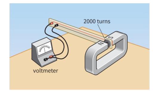
Figure 26.19 shows a search coil with 2000 turns and cross-sectional area 1.2 cm2. It is placed between the poles of a strong magnet. The magnetic field is perpendicular to the plane of the coil. The ends of the coil are connected to a voltmeter. The coil is then pulled out of the magnetic field,
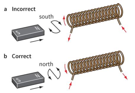
Use the ideas in the previous topic to explain what happens if a you stop pushing the magnet towards the coil shown in Figure 26.22, and b you pull the magnet away from the coil. a Incorrect south b Correct north
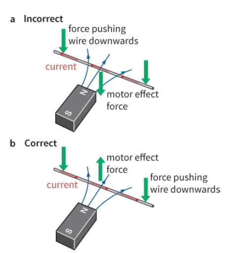
Draw a diagram to show the directions of the current caused by induced e.m.f. and of the opposing force if you now try to move the wire shown in Figure 26.23 upwards through the magnetic field. a Incorrect force pushing wire downwards current motor effect force b Correct motor effect force force
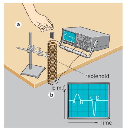
A bar magnet is dropped vertically downwards through a long solenoid, which is connected to an oscilloscope (Figure 26.24). The oscilloscope trace shows how the e.m.f. induced in the coil varies with time as the magnet accelerates downwards.a. Explain why an e.m.f. is induced in the coil as the
You can turn a bicycle dynamo by hand and cause the lamps to light up. Use the idea of Lenz’s law to explain why it is easier to turn the dynamo when the lamps are switched off than when they are on.
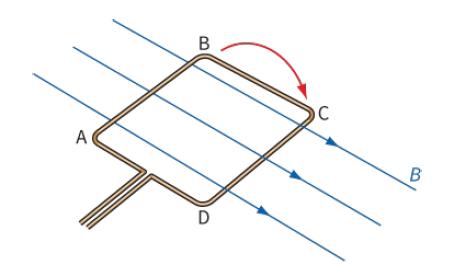
Figure 26.29 represents a coil of wire ABCD being rotated in a uniform horizontal magnetic field.Copy and complete the diagram to show the direction of the current caused by induced e.m.f. in the coil, and the directions of the forces on sides AB and CD that oppose the rotation of the coil. B A
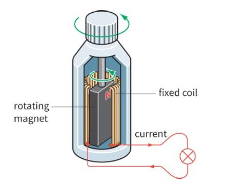
Does a bicycle generator (Figure 26.7) generate alternating or direct current? Justify your answer. fixed coil rotating magnet current
The peak e.m.f. induced in a rotating coil in a magnetic field depends on four factors: magnetic flux density B, area of the coil A, number of turns N and frequency f of rotation. Use Faraday’s law to explain why the magnitude of the induced e.m.f. must be proportional to each of these quantities.
Explain why, if a transformer is connected to a steady (d.c.) supply, no e.m.f. is induced across the secondary coil.
The alternating current I in ampere (A) in a filament lamp is represented by the equation:I = 1.5 sin (40t).Which of the following is correct?A. The angular frequency of the alternating current is 40 rad s−1.B. The frequency of alternating current is 40 Hz.C. The maximum current is 3.0 A.D. The
The maximum power dissipated in a resistor carrying an alternating current is 10 W.What is the mean power dissipated in the resistor?A. 5.0 WB. 7.1 WC. 10 WD. 14 W
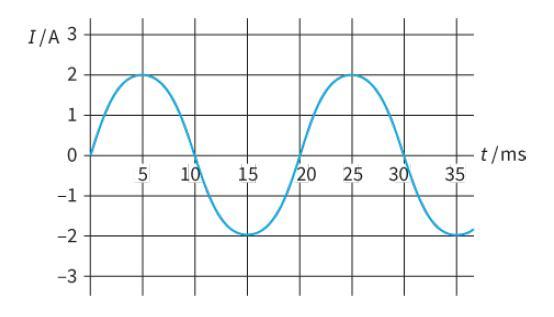
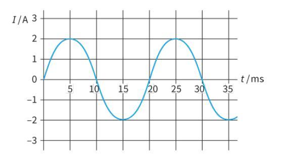
The following questions relate to the graph in Figure 27.2.a. Determine the values of I0 and ω.b. Write an equation to represent this alternating current. I/A 3 2 1 t/ms 35 10 15 20 25 30 -1 -2 -3
An alternating current, measured in amperes (A), is represented by the equation: I = 5.0 sin (120πt)a. Determine the values of I0, ω, f and T.b. Sketch a graph to represent the current.
Write down a general expression for the sinusoidal variation with time t of:a. An alternating voltage Vb. An alternating current I (you may assume that I and V are in phase)c. The power P dissipated due to this current and voltage.
An alternating voltage V, in volt (V), is represented by the equation:V = 300 sin (100πt)a. Determine the values of V0, ω and f for this alternating voltage.b. Calculate V when t = 0.002 s. (Remember that 100πt is in radians when you calculate this.)c. Sketch a graph to show two complete cycles
The alternating current I in ampere (A) in a circuit is represented by the equation:I = 2.0 sin (50πt).a. State the peak value of the current.b. Calculate the frequency of the alternating current.c. Sketch a graph to show two cycles of the variation of current with time. Mark the axes with
A heater of resistance 6.0 Ω is connected to an alternating current supply. The output voltage from the supply is 20 V r.m.s. Calculate:a. The average power dissipated in the heaterb. The maximum power dissipated in the heaterc. The energy dissipated by the heater in 5.0 minutes.
Sketch the CRO trace for a sinusoidal voltage of frequency 100 Hz and amplitude 10 V, when the timebase is 10 ms/cm and the Y-sensitivity is 10 V/cm.
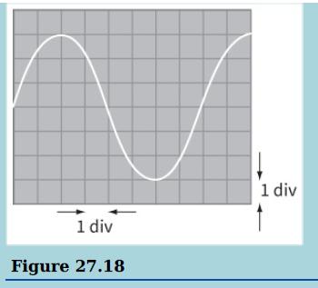
An oscilloscope is used to display the variation of voltage across a 200 Ω resistor with time. The trace is shown. The time-base of the oscilloscope is set at 5 ms div−1 and the Y-gain at 0.5 V div−1.Determine:a. The period and hence the frequency of the alternating voltageb. The peak voltage
The alternating current (in ampere, A) in a resistor is represented by the equation: I = 2.5 sin (100πt). Calculate the r.m.s. value for this alternating current.
a. State the relationship between the peak current I0 and the r.m.s. current Irms for a sinusoidally varying current.b. The current in a resistor connected to a steady d.c. supply is 2.0 A. When the same resistor is connected to an a.c. supply, the current in it has a peak value of 2.0 A. The
The mains supply to domestic consumers in many European countries has an r.m.s. value of 230 V for the alternating voltage.
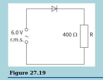
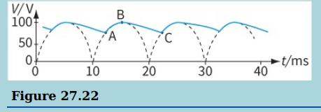
A sinusoidal voltage of 6.0 V r.m.s. and frequency 50 Hz is connected to a diode and a resistor R of resistance 400 Ω as shown in the diagram.a. Sketch a graph showing the variation with time of both the supply waveform (use a dotted line) and the voltage across R (use a solid line). Put numerical
Calculate the average power dissipated in a resistor of resistance 100 Ω when a sinusoidal alternating current has a peak value of 3.0 A.
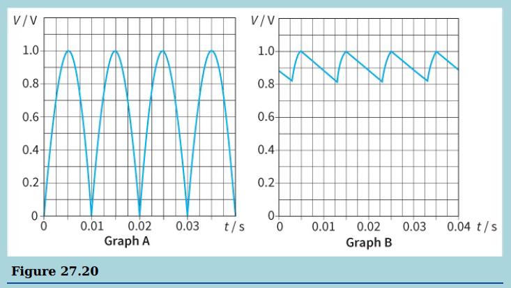
The rectified output from a circuit is connected to a resistor R of resistance 1000 Ω. Graph A shows the variation with time t of the p.d. V across the resistor. Graph B shows the variation of V when a capacitor is placed across R to smooth the output.Explain how the rectification is achieved.
The sinusoidal voltage across a 1.0 kΩ resistor has a peak value 325 V.a. Calculate the r.m.s. value of the alternating voltage.b. Use V = IR to calculate the r.m.s. current in the resistor.c. Calculate the average power dissipated in the resistor.d. Calculate the peak power dissipated in the
Electrical energy is supplied by a high-voltage power line that has a total resistance of 4.0 Ω. At the input to the line, the root-mean-square (r.m.s.) voltage has a value of 400 kV and the input power is 500 MW.a. i. Explain what is meant by root-mean-square voltage.ii. Calculate the minimum
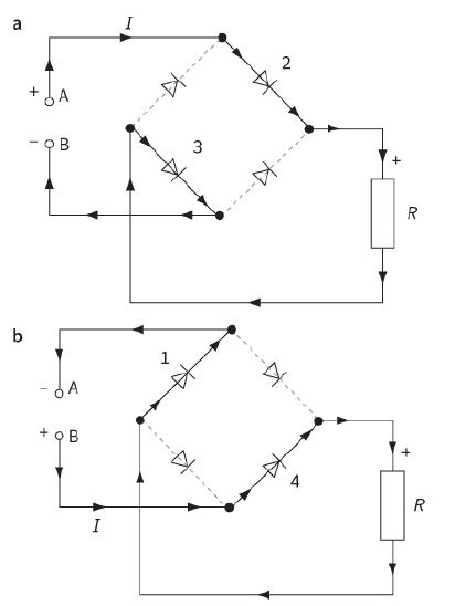
Explain why, when terminal B in Figure 27.13 is positive (during the negative cycles), only diodes 1 and 4 conduct. a 2 A R b 1 4 R I B. ---D----
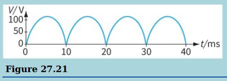
A student has designed a full-wave rectifier circuit.The output voltage for this circuit is taken across a resistor of resistance 120 Ω. The variation of the output voltage with time is shown.A capacitor is now connected across the resistor. The graph shows the new variation of the output voltage
Sketch the following voltage patterns:a. A sinusoidal alternating voltageb. The same voltage as part a, but half-wave rectifiedc. The same voltage as part b, but smoothedd. The same voltage as part a, but full-wave rectifiede. The same voltage as part d, but smoothed.
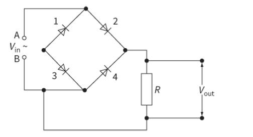
A student wires a bridge rectifier incorrectly as shown in Figure 27.16. Explain what you would expect to observe when an oscilloscope is connected across the load resistor R. Vin" B9 R Vout 2. 4. 3.
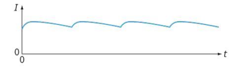
A bridge rectifier circuit is used to rectify an alternating current through a resistor. A smoothing capacitor is connected across the resistor. Figure 27.17 shows how the current varies. Use sketches to show the changes you would expect:a. If the resistance R of the resistor is increasedb. If the
The following questions relate to the graph in Figure 27.2.a. State the value of the current I and its direction when time t = 5 ms.b. Determine the time the current next has the same value, but negative.c. State the time T for one complete cycle (the period of the a.c).d. Determine the frequency
a. Calculate the mass in grams of a single atom of uranium-235 of mass 235 u.b. A small pellet of uranium-235 has a mass of 20 mg. For this pellet, calculate:i. The number of uranium atomsii. The number of moles.
There is an electric current in a wire of mass per unit length 40 g m−1. The wire is placed in a magnetic field of strength 0.50 T and the current is gradually increased until the wire just lifts off the ground.What is the value of the current when this happens?A. 0.080 AB. 0.20 AC. 0.78 AD. 780 A
The pendulum of a grandfather clock swings from one side to the other in 1.00 s. The amplitude of the oscillation is 12 cm.a. Calculate:i. The period of its motionii. The frequencyiii. The angular frequency.b. Write an equation of the form a = −ω2x to show how the acceleration of the pendulum
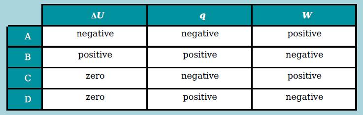
The first law of thermodynamics can be represented by the expression: ΔU = q + W. An ideal gas is compressed at constant temperature. Which row shows whether ΔU, q and W are negative, positive or zero during the change? AU W A negative negative positive B positive positive negative negative
Explain, in terms of kinetic energy, why the temperature of a stone increases when it falls from a cliff and lands on the beach below.
For the questions that follow, you will need the following value:R = 8.31 J mol−1 K−1Nitrogen consists of molecules N2. The molar mass of nitrogen is 28 g mol−1. For 100 g of nitrogen, calculate:a. The number of molesb. The volume occupied at room temperature and pressure (20 °C; 1.01 × 10⁵
For the questions that follow, you will need the following value:R = 8.31 J mol−1 K−1A sample of gas contains 3.0 × 1024 molecules. Calculate the volume of the gas at a temperature of 300 K and a pressure of 120 kPa.
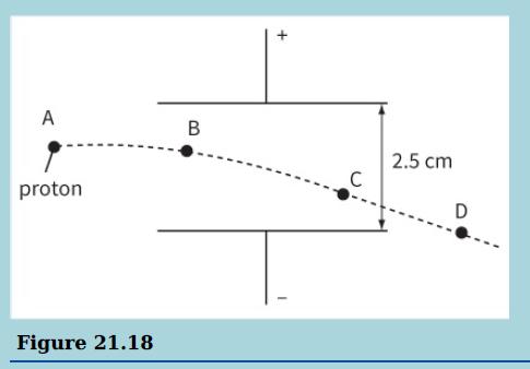
This diagram shows a proton as it moves between two charged parallel plates. The charge on the proton is + 1.6 × 10⁻¹⁹ C.a. Copy the diagram and draw the electric field between the parallel plates. The force on the proton when it is at position B is 6.4 × 10⁻¹⁴ N.b. In which direction does
a. State what is meant by an ideal gas.b. A cylinder contains 500 g of helium-4 at a pressure of 5.0 × 10⁵ Pa and at a temperature of 27 °C. You may assume that the molar mass of helium-4 is 4.0 g. Calculate:i. The number of moles of helium the cylinder holdsii. The number of molecules of
a. A cylinder contains 1.0 mol of an ideal gas. The gas is heated while the volume of the cylinder remains constant. Calculate the energy required to raise the temperature of the gas by 1.0 °C.b. Calculate the root-mean-square speed of a molecule of hydrogen-1 at a temperature of 100 °C.(Mass of
You will need the following data to answer the question.Proton mass = 1.67 × 10⁻²⁷ kgProton charge = +1.60 × 10⁻¹⁹ Cε0 = 8.85 × 10⁻¹² F m−1G = 6.67 × 10⁻¹¹ N m2 kg−2Two protons in the nucleus of an atom are separated by a distance of 10−15 m. Calculate the electrostatic
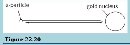
An α-particle emitted in the radioactive decay of radium has a kinetic energy of 8.0 × 10⁻¹³ J.a. i. Calculate the potential difference that an α-particle, initially at rest, would have to be accelerated through to gain this energy.ii. Calculate the speed of the α-particle at this kinetic
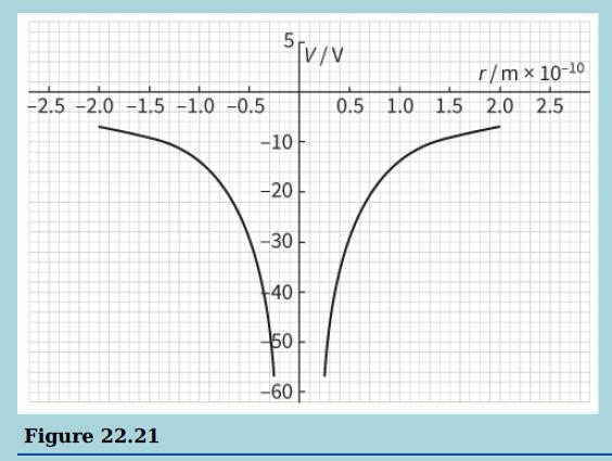
a. Define electric potential at a point.b. This graph shows the electrical potential near an antiproton.i. Determine the potential at a distance 0.53 × 10⁻¹⁰ m from the antiproton.ii. Determine the potential energy a positron would have at this distance.c. Use the graph to determine the
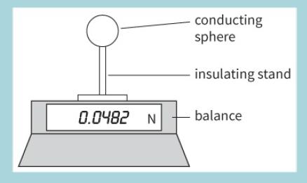
This diagram shows a conducting sphere of radius 0.80 cm carrying a charge of + 6.0 × 10⁻⁸ C resting on a balance.Figure 22.22a. Calculate the electric field at the surface of the sphere.b. An identical sphere carrying a charge of −4.5 × 10⁻⁸ C is held so that its centre is 5.0 cm
Calculate the charge on a 220 μF capacitor charged up to 15 V. Give your answer in microcoulombs (μC) and in coulombs (C).
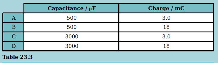
A capacitor has a potential difference of 6.0 V across its plates and stores 9.0 mJ of energy. Which row in the table gives the capacitance of the capacitor and the charge on its plates? Capacitance / uF Charge / mC A 500 3.0 B 500 18 C 3000 3.0 D 3000 18 Table 23.3
A charge of 1.0 × 10⁻³ C is measured on a capacitor with a potential difference across it of 500 V. Calculate the capacitance in farads (F), microfarads (μF) and picofarads (pF).
A capacitor in an electronic circuit is designed to slowly discharge through an indicator lamp.It is decided that the time taken for the capacitor to discharge needs to be increased. Four changes are suggested:1. Connect a second capacitor in parallel with the original capacitor.2. Connect a second
Calculate the average current required to charge a 50 μF capacitor to a p.d. of 10 V in a time interval of 0.01 s.
A 470 μF capacitor is connected across the terminals of a battery of e.m.f. 9 V. Calculate the charge on the plates of the capacitor.
A student connects an uncharged capacitor of capacitance C in series with a resistor, a cell and a switch. The student closes the switch and records the current I at intervals of 10 s. The results are shown in Table 23.1. The potential difference across the capacitor after 60 s is 8.5 V. Plot a
Calculate the p.d. across the terminals of a 2200 μF capacitor when it has a charge of 0.033 C on its plates.
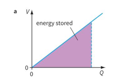
State the quantity represented by the gradient of the straight line shown in Figure 23.7a. a VA energy stored 0-
Calculate the capacitance of a capacitor if it stores a charge of 2.0 C when there is a potential difference of 5000 V across its plates.
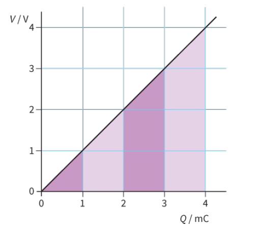
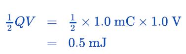
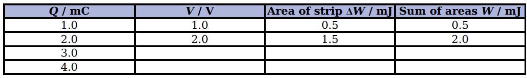
The graph of Figure 23.8 shows how V depends on Q for a particular capacitor.The area under the graph has been divided into strips to make it easy to calculate the energy stored.The first strip (which is simply a triangle) shows the energy stored when the capacitor is charged up to 1.0 V. The
Calculate the energy stored when a 470 μF capacitor has a potential difference of 12 V across its plates.
Calculate the energy stored in the following capacitors:a. A 5000 μF capacitor charged to 5.0 Vb. A 5000 pF capacitor charged to 5.0 Vc. A 200 μF capacitor charged to 230 V.
Calculate the energy stored on a capacitor if it stores 1.5 mC of charge when there is a potential difference of 50 V across it.
Which involves more charge, a 100 μF capacitor charged to 200 V or a 200 μF capacitor charged to 100 V? Which stores more energy?
A 5000 μF capacitor has a p.d. of 24 V across its plates.a. Calculate the energy stored on the capacitor.b. The capacitor is briefly connected across a bulb and half the charge flows off the capacitor. Calculate the energy dissipated in the lamp.
A 10,000 μF capacitor is charged to 12 V, and then connected across a lamp rated at ‘12 V, 36 W’.a. Calculate the energy stored by the capacitor.b. Estimate the time the lamp stays fully lit. Assume that energy is dissipated in the lamp at a steady rate.
A 4700 μF capacitor has a p.d. of 12 V across its terminals. It is connected to a resistor and the charge leaks away through the resistor in 2.5 s.a. Calculate the energy stored on the capacitor.b. Calculate the charge stored on the capacitor.c. Estimate the average current through the resistor.d.
In a simple photographic flashgun, a 0.20 F capacitor is charged by a 9.0 V battery. It is then discharged in a flash of duration 0.01 s. Calculate:a. The charge on and energy stored by the capacitorb. The average power dissipated during the flashc. The average current in the flash bulbd. The
An electronics engineer is designing a circuit in which a capacitor of capacitance of 4700 μF is to be connected across a potential difference of 9.0 V. He has four 4700 μF, 6 V capacitors available. Draw a diagram to show how the four capacitors could be used for this purpose.
a. Calculate the total capacitance of two 100 μF capacitors connected in parallel.b. Calculate the total charge they store when charged to a p.d. of 20 V.
Calculate the different capacitances that can be made from three 100 μF capacitors. For each value, draw the network that is used.
A capacitor of capacitance 50 μF is required, but the only values available to you are 10 μF, 20 μF and 100 μF (you may use more than one of each value). How would you achieve the required value by connecting capacitors in parallel? Give at least two answers.
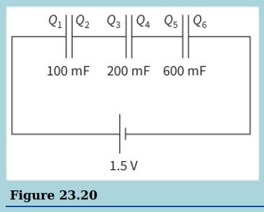
This diagram shows three capacitors connected in series with a cell of e.m.f. 1.5 V.a. Calculate the charges Q1 to Q6 on each of the plates.b. Calculate the p.d. across each capacitor. Q1||Q2 Q3 ||Q4 Qs || Q6 100 mF 200 mF 600 mF 1.5 V Figure 23.20
Calculate the total capacitance of three capacitors of capacitances 200 μF, 300 μF and 600 μF, connected in series.
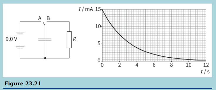
a. State one use of a capacitor in a simple electric circuit.b. This is a circuit used to investigate the discharge of a capacitor, and a graph showing the change in current with time when the capacitor is discharged.i. Deduce the resistance R of the resistor.ii. Explain why the current decreases
You have a number of identical capacitors, each of capacitance C. Determine the total capacitance when:a. Two capacitors are connected in seriesb. N capacitors are connected in seriesc. Two capacitors are connected in paralleld. N capacitors are connected in parallel.
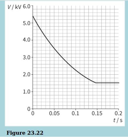
The spherical dome on a Van de Graaff generator has a diameter of 40 cm and the potential at its surface is 5.4 kV.a. i. Calculate the charge on the dome.ii. Calculate the capacitance of the dome.An earthed metal plate is moved slowly towards the sphere but does not touch it. The sphere discharges
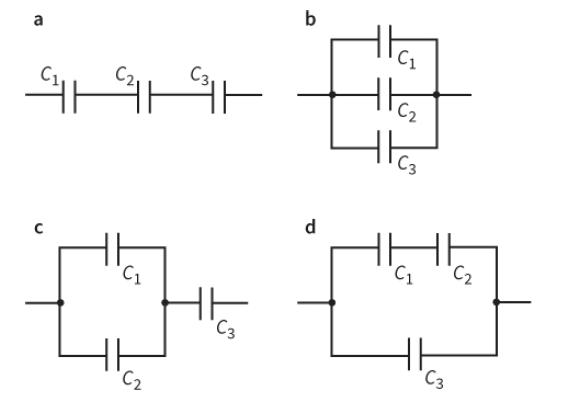
For each of the four circuits shown in Figure 23.14, calculate the total capacitance in μF if each capacitor has capacitance 100 μF. a C1 C3 d.
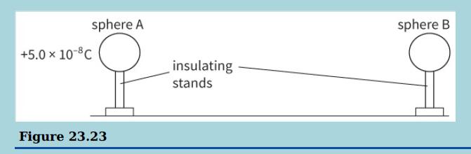
a. Show that the capacitance C of an isolated conducting sphere of radius r is given by the formula:C = 4πε0rThis diagram shows two identical conducting brass spheres of radius 10Cm mounted on insulating stands. Sphere A has a charge of + 5.0 × 10⁻⁸ C and sphere B is uncharged.b. i. Calculate
Given a number of 100 μF capacitors, how might you connect networks to give the following values of capacitance:a. 400 μF?b. 25 μF?c. 250 μF?
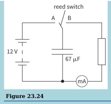
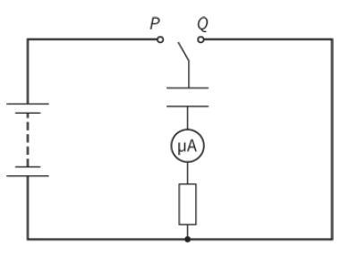
a. Define the term capacitance of a capacitor.b. This is a circuit that can be used to measure the capacitance of a capacitor.The reed switch vibrates back and forth at a frequency of 50 Hz. Each time it makes contact with A, the capacitor is charged by the battery so that there is a p.d. of 12 V
You have three capacitors of capacitances 100 pF, 200 pF and 600 pF. Determine the maximum and minimum values of capacitance that you can make by connecting them together to form a network. State how they should be connected in each case.
a. Explain what is meant by the time constant of a circuit containing capacitance and resistance.b. A circuit contains capacitors of capacitance 500 μF and 2000 μF in series with each other and in series with a resistance of 2.5 kΩ.i. Calculate the effective capacitance of the capacitors in
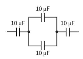
Calculate the capacitance in μF of the network of capacitors shown in Figure 23.15. 10 μ 10 μF 10 μF HE 10 μF
Three capacitors, each of capacitance 120 μF, are connected together in series. This network is then connected to a 10 kV supply. Calculate:a. Their combined capacitance in μFb. The charge storedc. The total energy stored.
A 20 μF capacitor is charged up to 200 V and then disconnected from the supply. It is then connected across a 5.0 μF capacitor. Calculate:a. The combined capacitance of the two capacitors in μFb. The charge they storec. The p.d. across the combinationd. The energy dissipated when they are
Estimate the capacitance of the Earth given that it has a radius of 6.4 × 10⁶ m. State any assumptions you make.
In the circuit in Figure 23.18, the resistance has a resistance of 2000 Ω, the capacitor has a capacitance of 1000 μF and the battery has an e.m.f. of 12 V.a. Calculate:i. The potential difference across the capacitor when it is fully charged by the batteryii. The charge stored by the capacitor
Show that the unit of the time constant (RC) is the second.
A 400 μF capacitor is charged using a 20 V battery. It is connected across the ends of a 600 Ω resistor with 20 V potential difference across its plates.a. Calculate the charge stored on the capacitor.b. Calculate the time constant for the discharging circuit.c. Calculate the time it takes the
A wire carrying a current is placed at right angles to a uniform magnetic field of magnetic flux density B. When the current in the wire is I, the magnetic force that acts on the wire is F.What is the force on the wire, placed in the same orientation, when the magnetic field strength is 2B and the
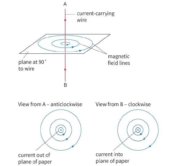
Sketch the magnetic field pattern around a long straight wire carrying an electric current. Now, alongside this first sketch, draw a second sketch to show the field pattern if the current flowing is doubled and its direction reversed. How does the pattern show that the field is stronger nearer the
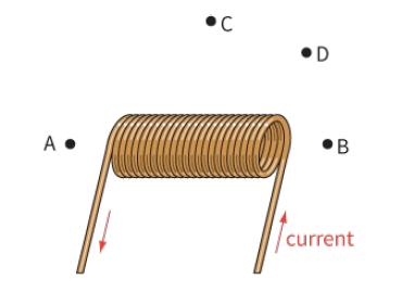
Sketch the diagram in Figure 24.6, and label the north and south poles of the electromagnet. Show on your sketch the direction of the magnetic field (as shown by the needle of a plotting compass) at each of the positions A, B, C and D. •C D A • B current
A current-carrying wire is placed in a uniform magnetic field.a. Describe how the wire should be placed to experience the maximum force due to the magnetic field.b. Describe how the wire should be placed to experience no force due to the magnetic field.
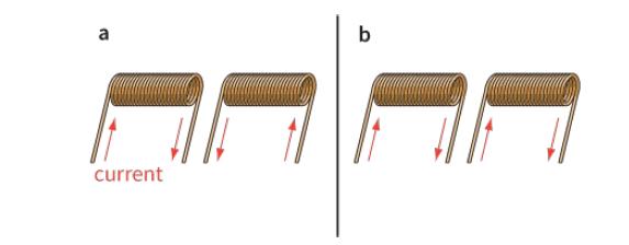
State which of the pairs of electromagnets shown in Figure 24.7 attract one another, and which repel. a current
A current-carrying conductor placed at right angles to a uniform magnetic field experiences a force of 4.70 × 10⁻³ N. Determine the force on the wire when, separately:a. The current in the wire is increased by a factor of 3.0b. The magnetic flux density is halvedc. The length of the wire in the
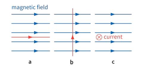
Figure 24.11 shows three examples of current-carrying conductors in magnetic fields. For each example, decide whether there will be a magnetic force on the conductor. If there is a force, in what direction will it act? Note the cross in the circle shows the current is into the plane of the paper,
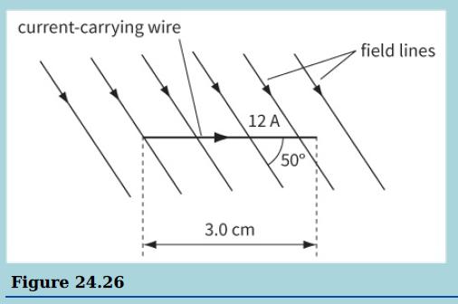
A copper wire carrying a current of 1.2 A has 3.0 cm of its length placed in a uniform magnetic field, as shown.The force experienced by the wire is 3.8 × 10⁻³ N when the angle between the wire and the magnetic field is 50°.a. Calculate the magnetic flux density.b. State the direction of the
A current of 0.20 A flows in a wire of length 2.50 m placed at right angles to a magnetic field of flux density 0.060 T. Calculate the force on the wire.
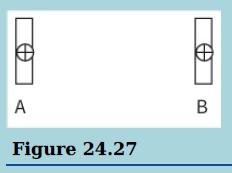
This diagram shows a view from above of two long, parallel strips of aluminium foil, A and B, carrying a current downwards into the paper.a. On a copy of the diagram, draw the magnetic field around and between the two strips.b. State and explain the direction of the forces caused by the current in
Showing 200 - 300
of 962
1
2
3
4
5
6
7
8
9
10
Step by Step Answers