New Semester
Started
Get
50% OFF
Study Help!
--h --m --s
Claim Now
Question Answers
Textbooks
Find textbooks, questions and answers
Oops, something went wrong!
Change your search query and then try again
S
Books
FREE
Study Help
Expert Questions
Accounting
General Management
Mathematics
Finance
Organizational Behaviour
Law
Physics
Operating System
Management Leadership
Sociology
Programming
Marketing
Database
Computer Network
Economics
Textbooks Solutions
Accounting
Managerial Accounting
Management Leadership
Cost Accounting
Statistics
Business Law
Corporate Finance
Finance
Economics
Auditing
Tutors
Online Tutors
Find a Tutor
Hire a Tutor
Become a Tutor
AI Tutor
AI Study Planner
NEW
Sell Books
Search
Search
Sign In
Register
study help
sciences
cambridge international as & a level physics coursebook
Cambridge International AS And A Level Physics Coursebook 3rd Edition David Sang, Graham Jones, Gurinder Chadha, Richard Woodside - Solutions
A filament lamp and a 220 Ω resistor are connected in series to a battery of e.m.f. 6.0 V. The battery has negligible internal resistance. A high-resistance voltmeter placed across the resistor measures 1.8 V.Calculate:a. The current drawn from the batteryb. The p.d. across the lampc. The total
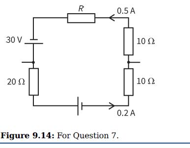
Use Kirchhoff’s second law to deduce the resistance R of the resistor shown in the circuit loop of Figure 9.14. R 0.5 A 30 V 10 Ω 20 Ω 10 Ω 0.2 A Figure 9.14: For Question 7.
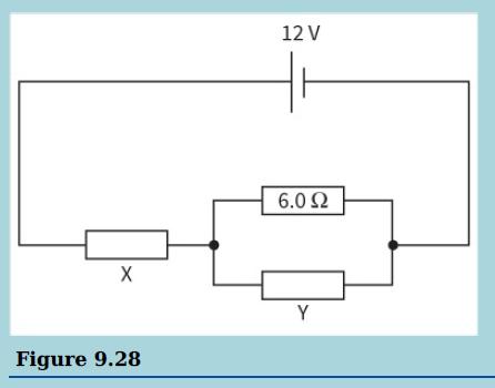
The circuit diagram shows a 12 V power supply connected to some resistors.The current in the resistor X is 2.0 A and the current in the 6.0 Ω resistor is 0.5A. Calculate:a. The current in resistor Yb. The resistance of resistor Yc. The resistance of resistor X. 12 V 6.02 Y Figure 9.28
Use the idea of the energy gained and lost by a 1 C charge to explain why two 6 V batteries connected together in series can give an e.m.f. of 12 V or 0 V, but connected in parallel they give an e.m.f. of 6 V.
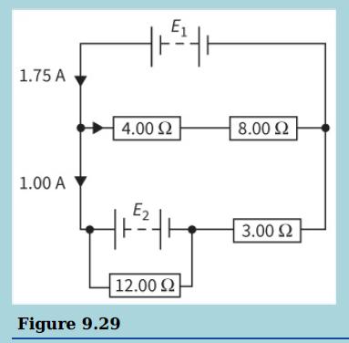
a. Explain the difference between the terms e.m.f. and potential difference.b. This circuit contains batteries and resistors. You may assume that the batteries have negligible internal resistance.i. Use Kirchhoff’s first law to find the current in the 4.00 Ω and 8.00 Ω resistors.ii. Calculate
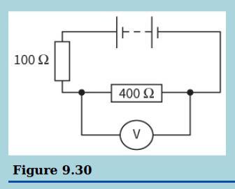
a. Explain why an ammeter is designed to have a low resistance.A student builds the circuit, as shown, using a battery of negligible internal resistance. The reading on the voltmeter is 9.0 V.b i. The voltmeter has a resistance of 1200 Ω. Calculate the e.m.f. of the battery.ii. The student now
Calculate the combined resistance of two 5 Ω resistors and a 10 Ω resistor connected in series.
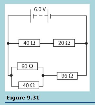
a. Explain what is meant by the resistance of a resistor.b. This diagram shows a network of resistors connected to a cell of e.m.f. 6.0 V.Show that the resistance of the network of resistors is 40 Ω.c. Calculate the current in the 60 Ω resistor. 6.0 V 40 Ω 20Ω 60 Ω 96 Ω 40 Ω Figure 9.31
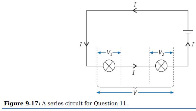
The cell shown in Figure 9.17 provides an e.m.f. of 2.0 V. The p.d. across one lamp is 1.2 V. Determine the p.d. across the other lamp. I IV -> Figure 9.17: A series circuit for Question 11.
Calculate the total resistance of four 10 Ω resistors connected in parallel.
You have five 1.5 V cells. How would you connect all five of them to give an e.m.f. of:a. 7.5 Vb. 1.5 Vc. 4.5 V?
Calculate the resistances of the following combinations:a. 100 Ω and 200 Ω in seriesb. 100 Ω and 200 Ω in parallelc. 100 Ω and 200 Ω in series and this in parallel with 200 Ω.
You are given one 200 Ω resistor and two 100 Ω resistors. What total resistances can you obtain by connecting some, none, or all of these resistors in various combinations?
Three resistors of resistances 20 Ω, 30 Ω and 60 Ω are connected together in parallel. Select which of the following gives their combined resistance:110 Ω, 50 Ω, 20 Ω, 10 Ω(No need to do the calculation!)
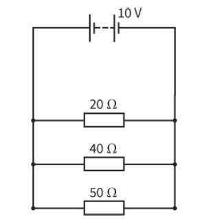
In the circuit in Figure 9.20 the battery of e.m.f. 10 V has negligible internal resistance. Calculate the current in the 20 Ω resistor shown in the circuit. 10 V 20 Ω 40 Ω 50 Ω
Determine the current drawn from the battery in Figure 9.20. 10 V 20 Ω 40 Ω 50 Ω
What value of resistor must be connected in parallel with a 20 Ω resistor so that their combined resistance is 10 Ω?
You are supplied with a number of 100 Ω resistors. Describe how you could combine the minimum number of these to make a 250 Ω resistor.
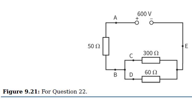
Calculate the current at each point (A–E) in the circuit shown in Figure 9.21. 600 V A 50 Ω E 300 Ω 60 Ω B Figure 9.21: For Question 22.
a. A 10 V power supply of negligible internal resistance is connected to a 100 Ω resistor. Calculate the current in the resistor.b. An ammeter is now connected in the circuit, to measure the current. The resistance of the ammeter is 5.0 Ω. Calculate the ammeter reading.
Table 10.1 shows the results of an experiment to measure the resistance of a carbon resistor whose resistance is given by the manufacturer as 47 Ω ± 10%.a. Plot a graph to show the I–V characteristic of this resistor.b. Do the points appear to fall on a straight line that passes through the
An element of an electric fire is made up from a length of nichrome wire of diameter 0.40 mm and length 5.0 m. The resistance of this element is R1. Another element, also made from nichrome, for a different electric fire, has a length of 2.0 m and a diameter of 0.20 mm. This element has a
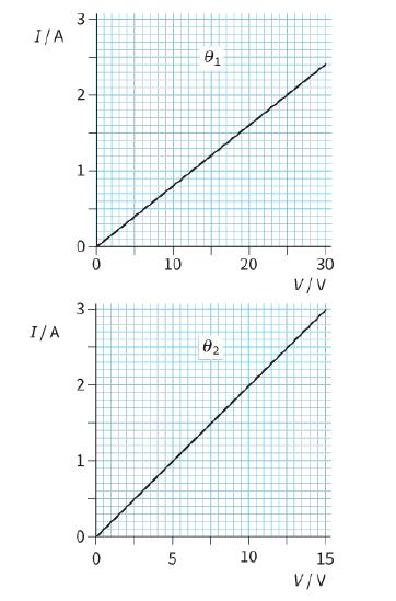
The two graphs in Figure 10.5 show the I–V characteristics of a metal wire at two different temperatures, θ1 and θ2.a. Calculate the resistance of the wire at each temperature.b. State which is the higher temperature, θ1 or θ2. 3+ I/A 2- 1. 10 20 30 V/V I/A 02 10 15 V/V 5. 3. 2.
An electrical component allows a current of 10 mA through it when a voltage of 2.0 V is applied. When the voltage is increased to 8.0 V, the current becomes 60 mA. Does the component obey Ohm’s law? Give numerical values for the resistance to justify your answer.
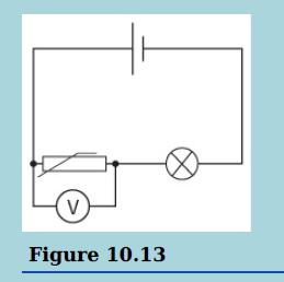
This is a circuit.Which line in the table shows the changes to the lamp and the voltmeter reading when the temperature rises? V Figure 10.13
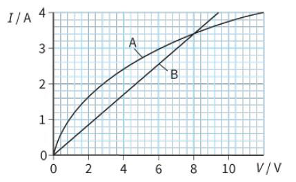
The graph in Figure 10.6 shows the I–V characteristics of two electrical components, a filament lamp and a length of steel wire.a. Identify which curve relates to each component.b. State the voltage at which both have the same resistance.c. Determine the resistance at the voltage stated in part
A student connects a thermistor to a battery and an ammeter. He places the thermistor in a beaker of water and gradually heats the water from 10 °C to its boiling point, recording the value of the current as he does so. He then plots a graph of the current in the thermistor against the temperature
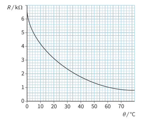
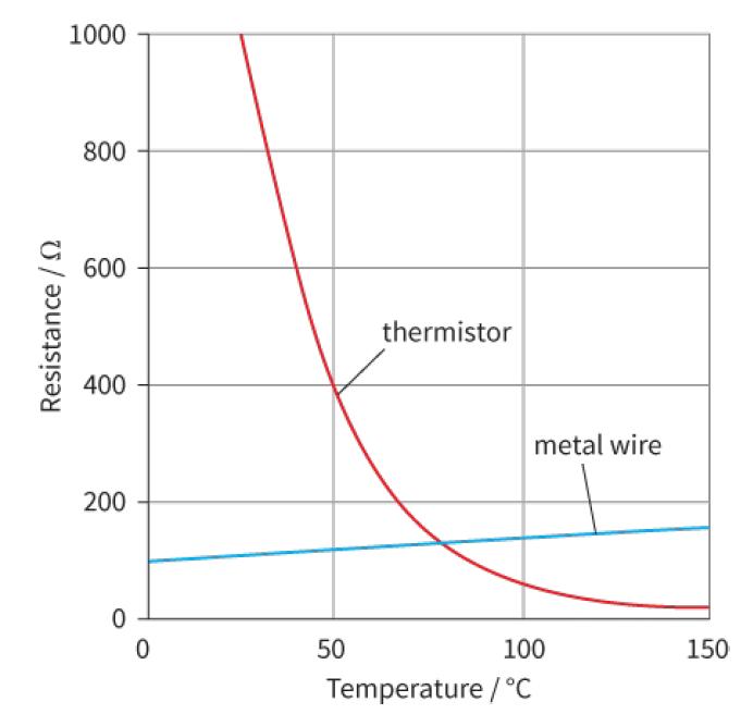
The graph in Figure 10.9 was obtained by measuring the resistance R of a particular thermistor as its temperature θ changed.a. Determine its resistance at:i. 20 °Cii. 45 °C.b. Determine the temperature when its resistance is:i. 5000 Ωii. 2000 Ω. R/kN 6- 3- 2- 1- 10 30 40 50 60 70 0/°C 20 4.
a. Describe the difference between the conduction processes in copper and in silicon, a semiconductor.b. Explain why the resistance of a metallic conductor increases with temperature while that of a semiconductor decreases.
A student connects a circuit with an NTC thermistor, a filament lamp and a battery in series. The lamp glows dimly. The student warms the thermistor with a hair dryer. What change will the student notice in the brightness of the lamp? Explain your answer.
The resistance of a metal wire changes with temperature. This means that a wire could be used to sense changes in temperature, in the same way that a thermistor is used.a. Suggest one advantage a thermistor has over a metal wire for this purpose.b. Suggest one advantage a metal wire has over a
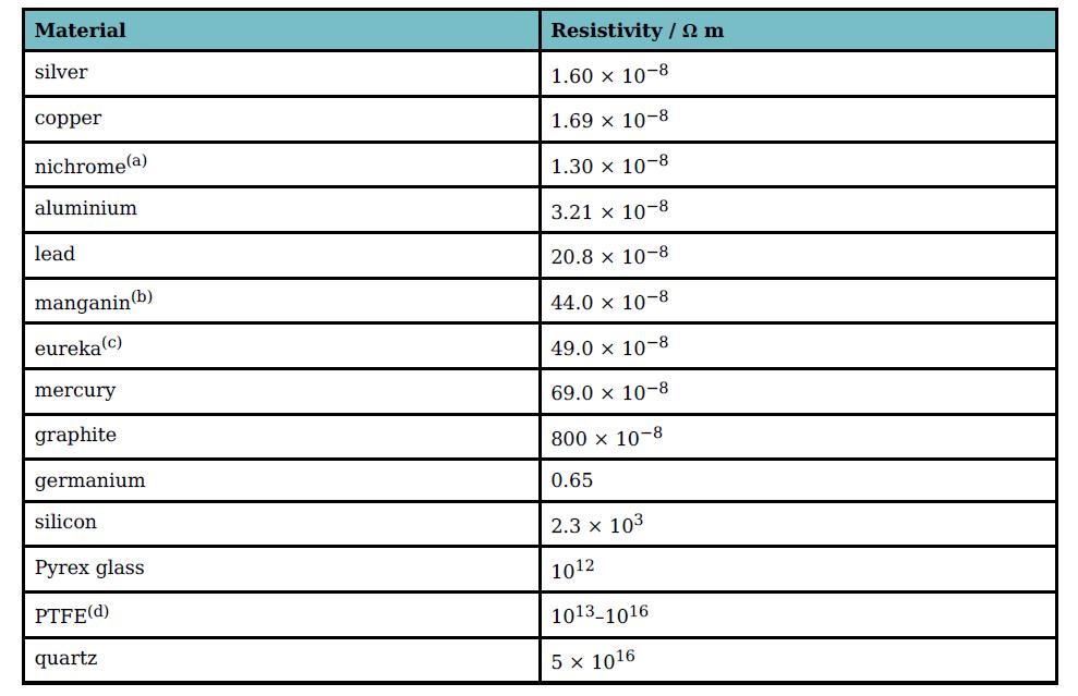
Use the resistivity value quoted in Table 10.2 to calculate the lengths of 0.50 mm diameter manganin wire needed to make resistance coils with resistances of:a. 1.0 Ωb. 5.0 Ωc. 10 Ω. Material Resistivity /2 m silver 1.60 x 10⁻⁸ сорper 1.69 x 10⁻⁸ nichrome(a) 1.30 x 10⁻⁸ aluminium 3.21 x 10⁻⁸
a. Explain why the resistance of a metal increases when its temperature increases.b. State two other factors that determine the resistance of a stated length of wire.c. When a potential difference of 1.5 V is applied across a 5.0 m length of insulated copper wire, a current of 0.24 A is measured in
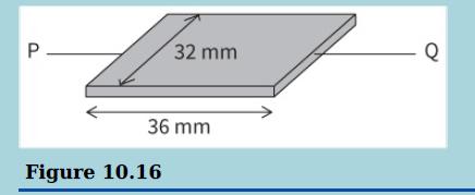
This diagram shows a piece of silicon of width 32 mm and length 36 mm. The resistance of the silicon between the points P and Q is 1.1 MΩ. Silicon has a resistivity of 2.3 × 10³ Ω m.a. Calculate the thickness of the piece of silicon.b. Calculate the current that would pass through the silicon if
A student is investigating the properties of a semiconducting diode. This diagram shows the circuit she builds.a i. Sketch a graph to show how the current in the diode would vary as the voltage across it is increased from 0 V to 1.0 V.ii. The supply is now connected in the reverse direction and
A 1.0 m length of copper wire has a resistance of 0.50 Ω.a. Calculate the resistance of a 5.0 m length of the same wire.b. What will be the resistance of a 1.0 m length of copper wire having half the diameter of the original wire?
A piece of steel wire has a resistance of 10 Ω. It is stretched to twice its original length. Compare its new resistance with its original resistance.
a. Explain what is meant by an ohmic conductor.b i. Sketch a graph of resistance R against voltage V for a wire of pure iron kept at constant temperature. Label this line X.ii. Sketch a graph of resistance R against voltage V for a second wire of impure iron, of the same diameter and the same
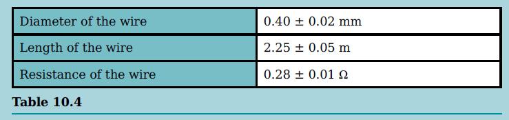
The readings in this table are recorded from an experiment to measure the resistivity of silver.a. Calculate the resistivity of silver.b i. Calculate the percentage uncertainty in each of the variables.ii. Use your answers to i to calculate the absolute uncertainty in the value of the resistivity
A battery of e.m.f. 5.0 V and internal resistance 2.0 Ω is connected to an 8.0 Ω resistor. Draw a circuit diagram and calculate the current in the circuit.
A resistor of resistance 6.0 Ω and a second resistor of resistance 3.0 Ω are connected in parallel across a battery of e.m.f. 4.5 V and internal resistance 0.50 Ω.What is the current in the battery?A. 0.47 AB. 1.8 AC. 3.0 AD. 11 A
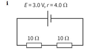
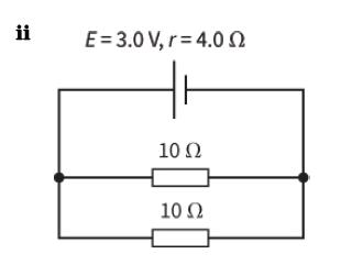
a. Calculate the current in each circuit in Figure 11.4.b. Calculate also the potential difference across the internal resistance for each cell, and the terminal p.d. E = 3.0 V, r = 4.0 n 10 Ω 10 Ω
This diagram shows a potential divider.What happens when the temperature decreases?A. The resistance of the thermistor decreases and Vout decreases.B. The resistance of the thermistor decreases and Vout increases.C. The resistance of the thermistor increases and Vout decreases.D. The
Four identical cells, each of e.m.f. 1.5 V and internal resistance 0.10 Ω, are connected in series. A lamp of resistance 2.0 Ω is connected across the four cells. Calculate the current in the lamp.
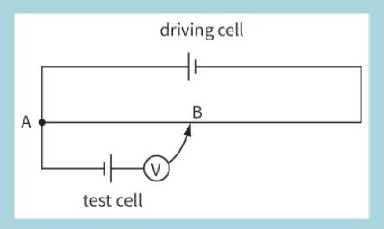
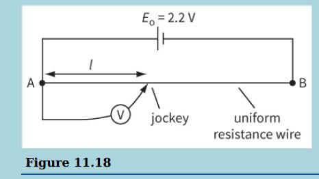
A student is asked to compare the e.m.f.s of a standard cell and a test cell. He sets up the circuit shown using the test cell.Figure 11.15a i. Explain why he is unable to find a balance point and state the change he must make in order to achieve balance. ii. State how he would recognise the
When a high-resistance voltmeter is placed across an isolated battery, its reading is 3.0 V. When a 10 Ωresistor is connected across the terminals of the battery, the voltmeter reading drops to 2.8 V. Use this information to determine the internal resistance of the battery.
The results of an experiment to determine the e.m.f. E and internal resistance r of a power supply are shown in Table 11.1. Plot a suitable graph and use it to find E and r. V/V 1.43 1.33 1.18 1.10 0.98 1/ A 0.10 0.30 0.60 0.75 1.00
a. Explain what is meant by the internal resistance of a cell.b. When a cell is connected in series with a resistor of 2.00 Ω there is a current of 0.625 A. If a second resistor of 2.00 Ω is put in series with the first, the current falls to 0.341 A.Calculate:i. The internal resistance of the
A car battery has an e.m.f. of 12 V and an internal resistance of 0.04 Ω. The starter motor draws a current of 100 A.a. Calculate the terminal p.d. of the battery when the starter motor is in operation.b. Each headlamp is rated as ‘12 V, 36 W’. Calculate the resistance of a headlamp.c. To what
a. State what is meant by the term e.m.f. of a cell.A student connects a high-resistance voltmeter across the terminals of a battery and observes a reading of 8.94 V. He then connects a 12 Ω resistor across the terminals and finds that the potential difference falls to 8.40 V.b. Explain why the
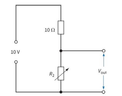
Determine the range of Vout for the circuit in Figure 11.7 as the variable resistor R2 is adjusted over its full range from 0 Ω to 40 Ω. (Assume the supply of e.m.f. 10 V has negligible internal resistance.) 10 Ω 10 V Vout R2
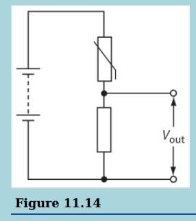
Design a circuit using the thermistor in Figure 11.10 that uses a cell of 10 V and produces an output voltage of 5 V at 50 °C. Explain whether the voltage output of your circuit increases or decreases as the temperature rises.
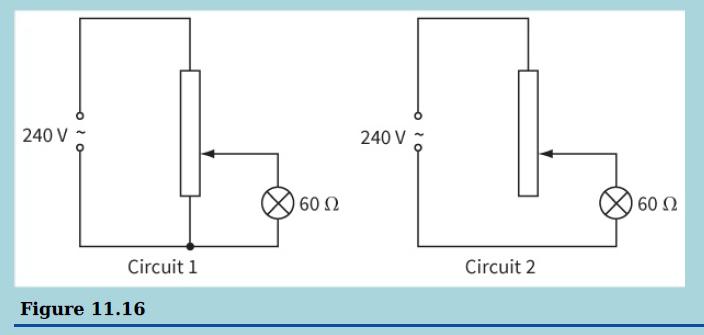
This diagram shows two circuits that could be used to act as a dimmer switch for a lamp.a. Explain one advantage circuit 1 has over circuit 2.b i. The lamp is rated at 60 W at 240 V. Calculate the resistance of the lamp filament at its normal operating temperature.ii. State and explain how the
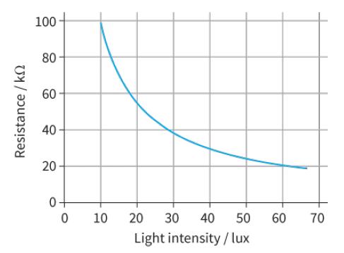
What is the voltage across the 3.0 kΩ resistor in Figure 11.9 when the light intensity is 10 lux? 100 80 60 40 20 0+ 10 20 30 40 50 60 70 Light intensity/lux Resistance / k
This circuit shows a potential divider. The battery has negligible internal resistance and the voltmeter has infinite resistance.a. State and explain how the reading on the voltmeter will change when the resistance of the variable resistor is increased.b. Resistor R2 has a resistance of 470 Ω.
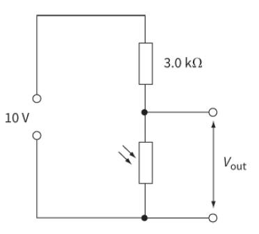
The circuit shown in Figure 11.8 produces a decreasing output voltage when the light intensity increases. How can the circuit be altered to produce an increasing output voltage as the light intensity increases? 3.0 kn 10 V Vout
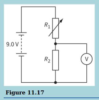
This is a potentiometer circuit.a i. Sketch a graph of reading on the voltmeter against length, l, as the jockey is moved from point A to point B.ii. State the readings on the voltmeter when the jockey is connected to A and when it is connected to B. (You may assume that the driver cell has
Explain how a thermistor can be used as a transducer.
A potentiometer, which consists of a driving cell connected to a resistance wire of length 100 cm, is used to compare the resistances of two resistors.a. Draw a diagram to show the circuits that are used to compare the two resistances.b. When resistor R1 alone is tested the length of resistance
State two similarities between an LDR and a thermistor.
To make a potentiometer, a driver cell of e.m.f. 4.0 V is connected across a 1.00 m length of resistance wire.a. What is the potential difference across each 1 cm length of the wire? What length of wire has a p.d. of 1.0 V across it?b. A cell of unknown e.m.f. E is connected to the potentiometer
Determine the wavelength and amplitude of each of the two waves shown in Figure 12.5. a b 10 15 20 25 30 Distance / cm Displacement / cm
What is the correct unit for intensity?A. J m2B. J s−1C. W m2D. W m−2
A microphone detects sound waves. The microphone is connected to a CRO. On the CRO screen, two complete cycles occupy five scale divisions along the x-axis. The calibrated time-base is set on 0.005 s div−1.Determine the frequency of the sound waves.
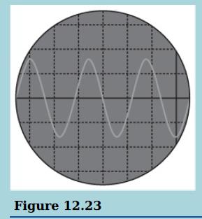
This image shows the screen of an oscilloscope. The time-base of the oscilloscope is set at 500 μs div−1.Calculate the time period of the signal and hence its frequency. Figure 12.23
a. State two main properties of electromagnetic waves.b. State one major difference between microwaves and radio waves.c i. Estimate the wavelength in metres of X-rays.ii. Use your answer to i to determine the frequency of the X-rays.
Using axes of displacement and distance, sketch two waves A and B such that A has twice the wavelength and half the amplitude of B.
A 100 W lamp emits electromagnetic radiation in all directions. Assuming the lamp to be a point source, calculate the intensity of the radiation:a. At a distance of 1.0 m from the lampb. At a distance of 2.0 m from the lamp.
A student is sitting on the beach, observing a power boat moving at speed on the sea. The boat has a siren emitting a constant sound of frequency 420 Hz. The boat moves around in a circular path with a speed of 25 m s−1. The student notices that the pitch of the siren changes with a regular
This diagram shows some air particles as a sound wave passes.a. On a copy of the diagram, mark:i. A region of the wave that shows a compression–label it Cii. A region of the wave that shows a rarefaction–label it R.b. Describe how the particle labelled P moves as the wave passes.c. The sound
A wave from a source has an amplitude of 5.0 cm and an intensity of 400 W m−2.a. The amplitude of the wave is increased to 10.0 cm. Calculate the intensity now.b. The intensity of the wave is decreased to 100 W m−2. Calculate the amplitude now.
In an experiment, a student is determining the speed of sound using the equation v = fλ. The values of frequency f and wavelength λ are shown below:f = 1000 ± 10 Hzλ = 33 ± 2 cmDetermine the speed v including the absolute uncertainty.
Sound is a mechanical wave that can be transmitted through a solid.Calculate the frequency of sound of wavelength 0.25 m that travels through steel at a speed of 5060 m s−1.
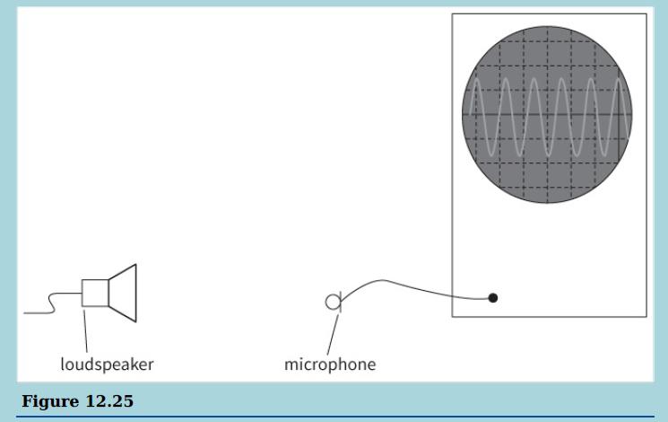
This diagram shows a loudspeaker producing a sound and a microphone connected to a cathode-ray oscilloscope (CRO).a. Sound is described as a longitudinal wave. Describe sound waves in terms of the movements of the air particles.b. The time-base on the oscilloscope is set at 5 ms div−1. Calculate
A cello string vibrates with a frequency of 64 Hz.Calculate the speed of the transverse waves on the cello string given that the wavelength is 140 cm.
The Doppler effect can be used to measure the speed of blood. Ultrasound, which is sound of high frequency, is passed from a transmitter into the body, where it reflects off particles in the blood. The shift in frequency is measured by a stationary detector, placed outside the body and close to the
An oscillator is used to send a transverse wave along a stretched string. The wavelength of the wave is 5.0 cm when the frequency of the oscillator is 30 Hz.For this wave, calculate:a. Its frequencyb. Its speed.
a. State what is meant by plane polarised light.b. Reflected light from the surface of water is partially plane polarised.Describe briefly how you could demonstrate this.c. Vertically plane polarised light is incident on three polarising filters. The transmission axis of the first Polaroid is
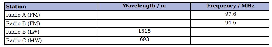
Copy and complete Table 12.2. (You may assume that the speed of radio waves is 3.00 × 10⁸ m s−1.) Station Wavelength / m Frequency / MHz Radio A (FM) 97.6 Radio B (FM) 94.6 Radio B (LW) 1515 Radio C (MW) 693
A plane’s engine emits a note of constant frequency 120 Hz. It is flying away from a stationary observer at a speed of 80 m s–1. Calculate:a. The observed wavelength of the sound received by the observerb. Its observed frequency.(Speed of sound in air = 330 m s−1.)
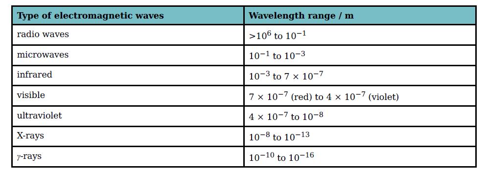
Copy Table 12.3. Add a third column showing the range of frequencies of each type of radiation. Type of electromagnetic waves Wavelength range / m radio waves >106 to 10-1 microwaves 10-1 to 10-3 infrared 10-3 to 7 x 10⁻⁷ visible 7 x 10⁻⁷ (red) to 4 x 10⁻⁷ (violet) ultraviolet 4 x 10⁻⁷ to 10-8
Study Table 12.3 and answer the questions.a. Which type of radiation has the narrowest range of wavelengths?b. Which has the second narrowest range?c. What is the range of wavelengths of microwaves, in millimetres?d. What is the range of wavelengths of visible light, in nanometres?e. What is the
For each of the following wavelengths measured in a vacuum, state the type of electromagnetic radiation to which it corresponds.a. 1 kmb. 3 cmc. 5000 nmd. 500 nme. 50 nmf. 10−12 m
For each of the following frequencies, state the type of electromagnetic wave to which it corresponds.a. 200 kHzb. 100 MHzc. 5 × 10¹⁴ Hzd. 1018 Hz
Explain what happens to unpolarised light incident at a Polaroid.
Plane polarised light of intensity 12 W m−2 is incident at a Polaroid.Calculate the intensity of the transmitted light when the angle between the plane of polarisation of the incident light and the transmission axis of the Polaroid isa. 45°b. 60°.
Plane polarised light is incident at a Polaroid.Calculate the angle θ, which gives transmitted light of intensity 30% that of the incident intensity of light.
On graph paper, draw two ‘triangular’ waves similar to those shown in Figure 13.4. (These are easier to work with than sinusoidal waves.) One should have wavelength 8.0 cm and amplitude 2.0 cm. The other should have wavelength 16.0 cm and amplitude 3.0 cm.Use the principle of superposition of
Rays of light from two coherent sources produces constructive interference.Which of the following cannot be the phase difference between these two rays?A. 0°B. 270°C. 360°D. 720°
A microwave oven (Figure 13.9) uses microwaves with a wavelength of 12.5 cm. The front door of the oven is made of glass with a metal grid inside; the gaps in the grid are a few millimetres across.Explain how this design allows us to see the food inside the oven, while the microwaves are not
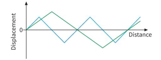
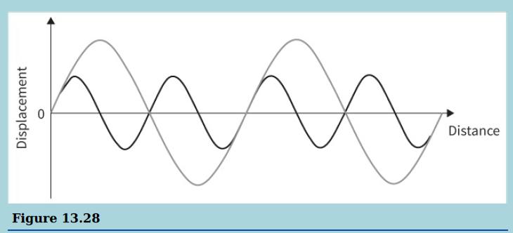
a. Copy the waves shown in the diagram onto a sheet of graph paper and use the principle of superposition to sketch the resultant wave.b. Compare the wavelength of the resultant wave with that of the component waves. Distance Figure 13.28
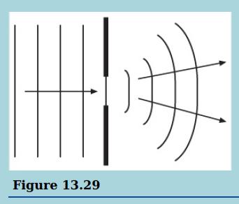
State how the diffracted pattern will change when:a. The wavelength of the incident wave is increasedb. The wavelength of the incident wave is decreased.
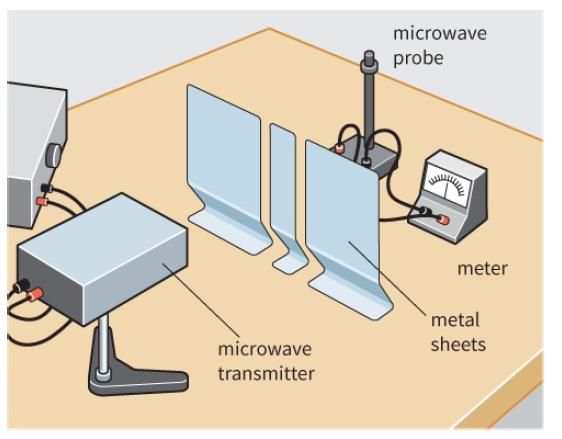
Look at the experimental arrangement shown in Figure 13.17. Suppose that the microwave probe is placed at a point of low intensity in the interference pattern.Suggest what will happen if one of the gaps in the barrier is now blocked. microwave probe meter metal microwave sheets transmitter
Explain why, in remote mountainous regions, such as the Hindu Kush, radio signals from terrestrial transmitters can be received, but television reception can only be received from satellite transmissions.
Draw sketches of displacement against time to illustrate the following:a. Two waves having the same amplitude and in phase with one anotherb. Two waves having the same amplitude and with a phase difference of 90°c. Two waves initially in phase but with slightly different wavelengths.
A constant frequency signal from a signal generator is fed to two loudspeakers placed 1.5 m apart. A student, who is 8.0 m away from the loudspeakers, walks across in a line parallel to the line between the loudspeakers. The student measures the distance between successive spots of loudness to be
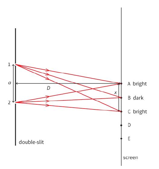
Consider points D and E on the screen in Figure 13.22, where BC = CD = DE. State and explain what you would expect to observe at D and E. 1 A bright B dark 2 C bright D E double-slit screen
Two signal generators feed signals with slightly different frequencies to two separate loudspeakers. Suggest why a sound of continuously rising and falling loudness is heard.
The student in Worked example 1 moved the screen to a distance of 4.8 m from the slits. Determine the fringe separation x now.
One of the spectral lines from a hydrogen discharge lamp has wavelength 656 nm. This light is incident normally at a diffraction grating with 5000 lines cm−1.Calculate the angles for the first- and second-order maxima for this light.
Showing 600 - 700
of 962
1
2
3
4
5
6
7
8
9
10
Step by Step Answers