New Semester
Started
Get
50% OFF
Study Help!
--h --m --s
Claim Now
Question Answers
Textbooks
Find textbooks, questions and answers
Oops, something went wrong!
Change your search query and then try again
S
Books
FREE
Study Help
Expert Questions
Accounting
General Management
Mathematics
Finance
Organizational Behaviour
Law
Physics
Operating System
Management Leadership
Sociology
Programming
Marketing
Database
Computer Network
Economics
Textbooks Solutions
Accounting
Managerial Accounting
Management Leadership
Cost Accounting
Statistics
Business Law
Corporate Finance
Finance
Economics
Auditing
Tutors
Online Tutors
Find a Tutor
Hire a Tutor
Become a Tutor
AI Tutor
AI Study Planner
NEW
Sell Books
Search
Search
Sign In
Register
study help
engineering
telecommunication engineering
Digital Signal Processing 3rd Edition Jonh G. Proakis, Dimitris G.Manolakis - Solutions
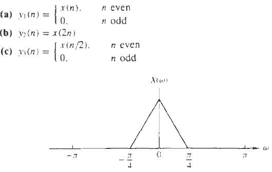
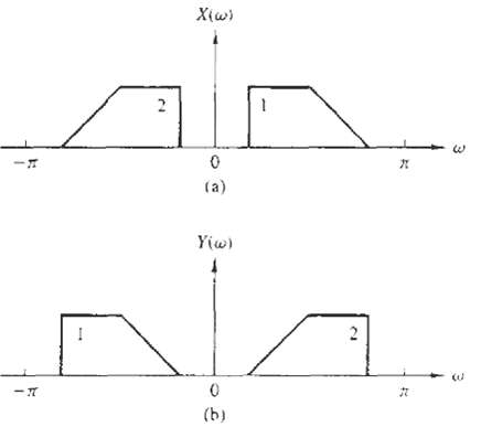
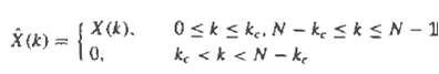
From a discrete-time signal x(n) with Fourier transform X(?). Shown in figure determine and sketch the Fourier transform of the following signals: Note that y1 (n) = x (n)s(n), where s(n) = { . . . 0, 1, 0, 1, 0, 1, 0, 1 . . . }
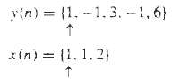
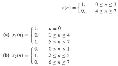
The following input-output pairs have been observed during the operation of various system, determine their frequency response if each of the above system is LTI.
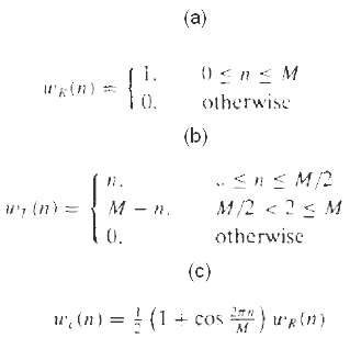
(a) Determine and sketch the Fourier transform WR(?) of the rectangular sequence. (b) Consider the triangular sequence, determine and sketch the Fourier transform WT(?) of ?T(n) by expressing it as the convolution of a rectangular sequence with itself. (c) Consider the sequence, determine and
Consider an LTI system with impulse response h(n) = (1/2)n u(n). (a) Determine and sketch the magnitude and phase response |H (?)| (b) Determine and sketch the magnitude and phase spectra for the input and output signals for the following inputs:
An FIR filter is described by the difference equation y(n) = x(n) + x(n ? 10) (a) Compute and sketch its magnitude and phase response. (b) Determine its response to theinputs
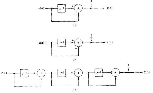
Determine the transient and steady-state responses of the FIR filter shown in figure to the input signal x(n) = 10elπnRu(n). Let b = 2 and y(-1) = y(-2) = y(-3) = y(-4) = 0.
Consider the FIR filter y(n) = x(n) + x(n – 4) (a) Compute and sketch its magnitude and phase response. (b) Compute its response to the input x(n) = cos π/2n + cos π/4n -∞ < n < ∞ (c) Explain the results obtained in part (b) in terms of the magnitude and phase
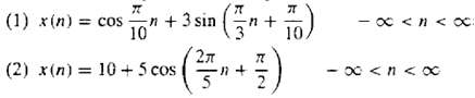
Determine the steady-state and transient responses of the system y(n) = ½ [x(n) – x(n – 2 )] to input signal x(n) = 5 + 3cos (π/2n + 600) -∞ < n < ∞
Determine our discussions it is apparent that an LTI system cannot produce frequencies at its output that are different from those applied in its input. Thus, if a system creates “new” frequencies, it must be nonlinear and/or time varying. Determine the frequency content of the outputs of the
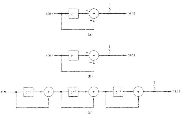
Determine and sketch the magnitude and phase response of the systems shown in figure. (a) through (c).
Determine the magnitude and phase response of the multipath channel y(n) = x(n) + x(n – M) At what frequencies does H(ω) = 0 ?
Consider the filter y(n) = 0.9y (n – 1) + bx (n) (a) Determine b so that |H(0) = 1.| (b) Determine the frequency at which |H(ω)| = 1/√2. (c) Is this filter low pass, band pass, or high pass? (d) Repeat parts (b) and (c) for the filter y(n) = -0.9y(n – 1) + 0.1x (n).
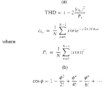
Harmonic distortion in digital sinusoidal generators an ideal sinusoidal generator produces the signal x(n) = cos2?f0n -? Total power(a) Show that(b) By using the Taylor approximation compute one period of x (n) for f0 = 1/96, 1/32, 1/256 by increasing the number of
Measurement of the total harmonic distortion in quantized sinusoids let x(n) be a periodic sinusoidal signal with frequency f0 = k/N, that is, x(n) = sin 2π f0n.(a) Write a computer program that quantizes the signal x(n) into b bits or equivalently into L = 2b levels by using rounding. The
Consider the discrete-time system y(n) = ay(n – 1) + (1 – 0) x (n) n ≥ 0 where a = 0.9 an dy (-1) = 0. (a) Compute and sketch the output y1(n) of the system to the input signals x1(n) = sin2πf1n 0≤n≤100, where f1 = ¼. f2 = 1/5, f3 = 1/10, f4 = 1/20 (b) Compute and
Consider an LTI system with impulse response h(n) = (1/3)|n|(a) Determine and sketch the magnitude and phase response H(ω)| and < H (ω), respectively.(b) Determine and sketch the magnitude and phase spectra for the input and output signals for the following inputs:(1) x(n) = cos 3πn/8. -∞
Time-domain sampling consider the continuous-time signal(a) Compute analytically the spectrum Xa (F) of xa (t).(b) Compute analytically the spectrum of the signal x (n) = xa (nT). T = 1/F.(c) Plot the magnitude spectrum |Xa (F)| for F0 = 10Hz.(d) Plot the magnitude spectrum |Xa (F)| for F0 = 10.
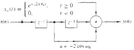
Consider the digital filter shown in figure (a) Determine the input-output relation and the impulse response h(n). (b) Determine and sketch the magnitude |H(?)| and the phase response (c) When ?0 = ?/2, determine the output y(n) to the input x(n) = 3 cos (?/3n + 30). -?
Consider the FIR filter y (n) = x(n) – x (n – 4) (a) Computer and sketch its magnitude and phase response. (b) Compute its response to the input x(n) = cos π/2n + cos π/4n. -∞ < n < ∞ (c) Determine the results obtained in part (b) in terms of the answer given in part
Determine the steady-state response of the system y(n) = ½ [x(n) – x (n – 2)] to the input signal x(n) = 5 + 3 cos(π/2n + 60) + 4 sin (πn + 45). -∞ < n < ∞.
Recall from Problem 4.32 that an LTI system cannot produce frequencies at its output that are different from those applied in its input. Thus if a system creates “new” frequencies, it must be nonlinear and/or time varying and determine the output spectra when the input spectrum is (a) y
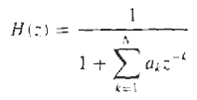
Consider an LTI system with impulse response h(n) = [(1/4)u cos(π/4n)] (a) Determine its system function H(z) (b) Is it possible to implement this system using a finite number of adders, multipliers and unit delays? If yes, how? (c) Provide a rough sketch of |H(ω)| using the pole-zero
An FIR filter is describe by the difference equation y(n) = x(n) ? x (n ? 10) (a) Compute and sketch its magnitude and phase response. (b) Determine its response to theinputs
The frequency response of an ideal bandpass filter is given by(a) Determine its impulse response(b) Show that this impulse response can be expressed as the product of cos(n?/4) and the impulse response of a lowpass filter.
Consider the system describe by the difference equation y(n) = ½ y(n – 1) + x(n) + ½ (n – 1).(a) Determine its impulse response.(b) Determine its frequency response:(1) From the impulse response(2) From the difference equation(c) Determine its response to the input x(n) = cos (π/2n + π/4)
Sketch roughly the magnitude |X (?)| of the Fourier transforms corresponding to the pole-zero patterns given in figure.
Design an FIR filter that completely blocks the frequency ω0 = π/4 and then computer its output if the input is x (n) = (sin π/4n) u (n) for n = 0, 1, 2, 3, 4. Does the filter fulfill your expectation? Explain.
A digital filter is characterized by the following properties:(1) It is high pass and has one pole and one zero.(2) The pole is at a distance r = 0.9 from the origin of the z-plane.(3) Constant signals do not pass through the system.(a) Plot the pole-zero pattern of the filter and determine its
A causal first-order digital filter is described by the system function(a) Sketch the direct form I and direct form II realization of this filter and find the corresponding difference equations(b) For a = 0.5 and b = -0.6, sketch the pole-zero pattern. Is the system stable? Why?(c) For a = 0.5 and
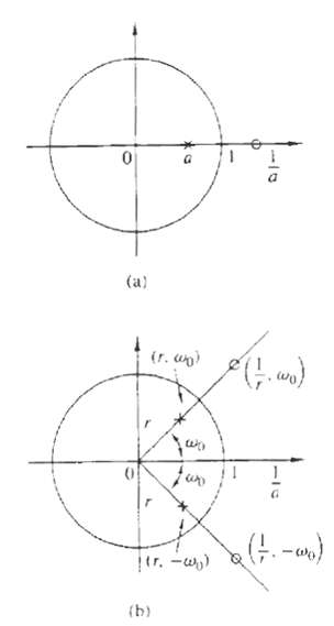
Derive the expression for the resonant frequency of a two-pole filter with poles at p1 = rel? And p2 = p1*. Given by
Determine and sketch the magnitude and phase responses of the Hanning filter characterized by the (moving average) differenceequation
A causal LTI system excited by the input x(n) = (1/4)nu (n) + u(- n ? 1) produce an output y(n) with z-transform (a) Determine the system function H(z) and its ROC. (b) Determine the output y(n) of thesystem.
Determine the coefficients of a linear-phase FIR filter y(n) = b0x(n) + b1x (n – 1) + b2x (n – 2) such that:(a) It rejects completely a frequency component at ω0 = 2π/3.(b) Its frequency response is normalized so that H(0) = 1.(c) Compute and sketch the magnitude and phase response of the
Determine the frequency response H(?) of the following moving average filters. Which filter provides better smoothing? Why?
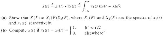
The convolution x(t) of two continuous-time signals x1(t) and x2(t), from which at least one is non periodic, is defined by (c) Determine the spectrum of x(t) using the results if part(a).
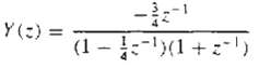
Compute the magnitude and phase response of a filter with system function H (z) =1+z-1+z-2+.+z-8If the sampling frequency is Fs = 1 kHz, determine the frequencies of the analog sinusoids that cannot pass through the filter.
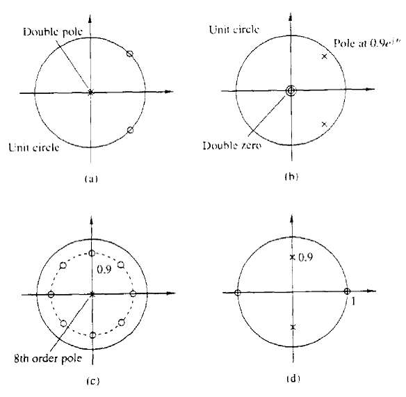
A second-order system has a double pole at p1,2 = 0.5 and two zeros at z1.2 = e±j3π/4. Using geometric arguments, choose the gain G of the filter so that |H (0)| = 1.
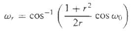
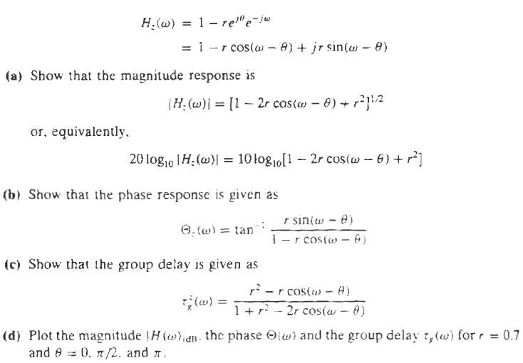
In this problem we consider the effect of a single zero on the frequency response of a system. Let z = rej? be zero inside the unit circle (r
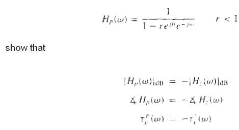
In this problem we consider the effect of a signal pole on the frequency response of a system. Hence, we let. Where Hz (?) and Tkz are defined in Problem 4.61..
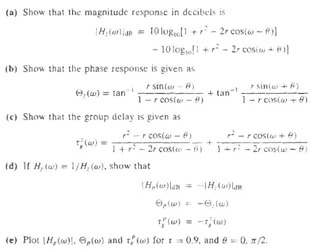
In this problem we consider the effect of complex-conjugate pair of poles and zeros on the frequency response of a system. Let Hz (?) = (1 ? rej0 e-j? ) (1- re-j0e-j?)
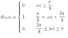
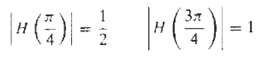
Determine the 3-dB bandwidth of the filters (0
Design a digital oscillator with adjustable phase, that is, a digital filter which produces the signal y(n) = cos(ω0n + θ) u (n)
This problem provides another derivation of the structure for the coupled-form oscillator by considering the system y(n) = ay(n – 1) + x(n), for a = ejω0. Let x(n) be real. Then y(n) is complex. Thus, y(n) = yR(n) + jyl(n) (a) Determine the equations describing a system with one input x(n)
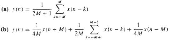
Consider a filter with system function(a) Sketch the pole-zero patterns.(b) Using geometric arguments. Show that for r ? 1. The system is a notch filter and provide a rough sketch of its magnitude response if ?0 = 60.(c) For ?0 = 60. Choose b0 so that the maximum value of |H (?)| is 1.(d) Draw a
Design an FIR digital filter that will reject a very strong 60-Hz sinusoidal interference contaminating a 200-Hz useful sinusoidal signal. Determine the gain of the filter so that the useful signal does not change amplitude. The filter works at a sampling frequency Fs = 500 samples/s. Compute the
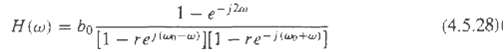
Determine the gain b0 for the digital resonator described by (4.5.28) so that |H (?0)| = 1.
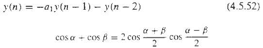
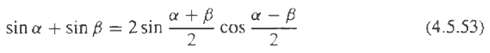
Demonstrate that the difference equation given in (4.5.52) can be obtained by applying the trigonometric identity, where ? = (n + 1) ?0, ? = (n ? 1) ?0, and y(n) = cos ?0n. Thus shown that the sinusoidal signal y (n) = A cos ?0n can be generated from (4.5.52) by using of the initial condition y (-
Use the trigonometric identify in (4.5.53) with ? = n?0 and ? = (n ? 2) ?0 to derive the difference equation for generating the sinusoidal signal y(n) = A sinn?0. Determine the corresponding initial conditions.
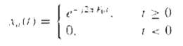
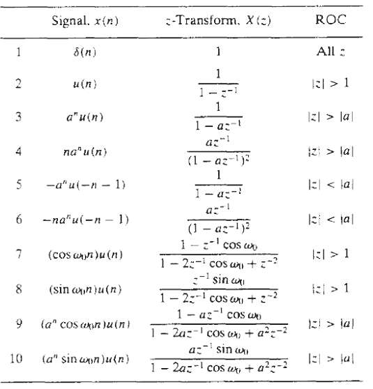
Using the z-transform pairs 8 and 9 in table 3.3, determine the difference equations for the digital oscillators that have impulse responses h(n) = Acosn?0u(n) and h(n) = Asinn?0u(n), respectively. la| (1 az-) " alt="Using the z-transform pairs 8 and 9 in table 3.3, determine the">
Determine the structure for the coupled-form oscillator by combining the structure for the digital oscillators obtained in problem 4.72.
Convert the high pass filter with system function into a notch filter that rejects the frequency ω0 = π/4 and its harmonics. (a) Determine the difference equation. (b) Sketch the pole-zero patterns. (c) Sketch the magnitude response for the both filters.
Choose L A and M for a lunar filter that must have narrow pass bands at (k ± ΔF) cycles/day. Where k = 1, 2, 3 ... and ΔF = 0.067726.
(a) Show that the systems corresponding to the pole-zero patterns of figure are all- pass.(b) What is the number of delays and multipliers required for the efficient implementation of a second-order all-passsystem?
(a) Show that the systems corresponding to the pole-zero patterns of figure are all- pass.(b) What is the number of delays and multipliers required for the efficient implementation of a second-order all-passsystem?
Determine the coefficients {h(n)} of a high pass linear phase FIR filter of length M = 4 which has an anti symmetric unit sample response h(n) = -h(M ? 1 ? n) and a frequency response that satisfies the condition
A discrete-time system with input x (n) and out put y (n) is described in the frequency domain by the relation y(ω) = e-j2πωX(ω) + dX(ω)/dω (a) Compute the response of the system to the input x(n) = δ(n). (b) Check if the system is LTI and stable.
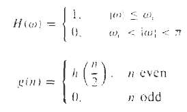
Consider an ideal low pass filter with impulse response h (n) and frequency responses. What is the frequency response of the filter definedby
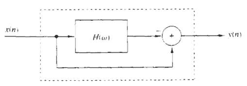
Consider the system shown in figure. Determine its impulse response and its frequency response if the H(?) is:(a) Low pass with cut off frequency ?0.(b) High pass with cut off frequency ?0.
Frequency inverters have been used for many years for speech scrambling. Indeed, a voice signal x (n) becomes unintelligible if we invert its spectrum as shown in figure(a) Determine how frequency inversion can be performed in the time domain.(b) Design aun-scramble.
A low pass filter is described by the difference equation y(n) = 0.9y(n – 1) + 0.1x(n) (a) By performing a frequency translation of π/2, transforms the filter into a band pass filter. (b) What is the impulse response of the band pass filter? (c) What is the major problem with the
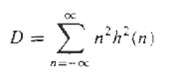
Consider a system with a real-valued impulse response h(n) and frequency response H(?) = |H (?)| ej? (?) The quantity provides a measure of the ?effective duration? of h(n) (a) Express D in terms of H(?). (b) Show that D is minimize for ?(?) = 0.
Consider the low pass filters y(n) = ay(n – 1) + bx(n) 0 < a < 1 (a) Determine b so that |H(0)| = 1. (b) Determine the 3-dB bandwidth ω3 for the normalized filter in part (a). (c) How does the choice of the parameter a affect ω3? (d) Repeat parts (a) through (c) for the high pas
Sketch the magnitude and phase response of the multipath channel y(n) = x(n) + ax(n – M) a > 0, for a < < 1
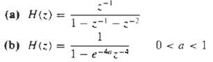
Determine the system function and the pole-zero location for the systems shown in figure (a) through (c), and indicate whether or not the system arestable.
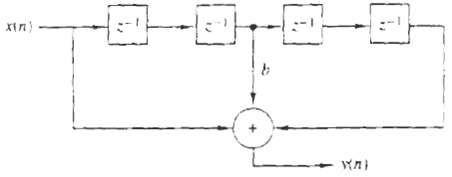
Determine and sketch the impulse response and the magnitude and phase responses of the FIR filter shown in figure, for b =1 and b-1
Consider the systemy(n) = x(n) – 0.95x(n – 6)(a) Sketch its pole-zero patterns.(b) Sketch its magnitude response using the pole-zero plots.(c) Determine the system function of its causal inverse system.(d) Sketch the magnitude response of the inverse system using the pole-zero plots.
Determine the impulse response and the difference equation for all possible system specified by the systemfunctions.
Determine the impulse response of a causal LTI system which produces the response when excited by the inputsignal
The system y(n) = ½y(n – 1) + x(n) is exited with the input x(n) = (1/4)nu(n).Determine the sequences rxx(l), rhh(l), rxy(l), and ryy(l).
Determine if the following FIR systems are minimum phase
Can you determine the coefficients of the all-pole system, If you know its order N and the values h(0), h(1) . . . h(L ? 1) of its impulse response? How? What happens if you do not know N?
Consider the pole-zero system(a) Determine h(0), h(1), h(2) and h(3) in terms of a and b.(b) Let rhh(l) be the auto correlation sequence of h(n). Determine rhh(0), rhh(1), rhh(2), and rhh(3) in terms of a andb.
Let x(n) be a real-valued minimum-phase sequence. Modify x(n) to obtain another real-valued minimum-phase sequence y(n) such that y(0) = x(0) and y(n) = |x (n)|.
The frequency response of a stable LTI system is known to be real and even. Is the inverse system stable?
Let h(n) be a real filter with non zero linear or nonlinear phase response. Show that the following operations are equivalent to filtering the signal x(n) with a zero-phase filter(a) g(n) = h(n) * x(n) f(n) = h(n) * g(–n) y(n) = f(–n)(b) g(n) = h(n) * x (n) f(n) = h(n) * x(–n)
Check the validity of the following statements:(a) The convolution of two minimum-phase sequences is always minimum-phase sequence.(b) The sum of two minimum-phase sequences is always minimum phase.
Determine the minimum-phase system whose squared magnitude response is givenby:
Consider an FIR system with the following system function:? H(z) = (1 ? 0.8ej?/2z-1)(1 ? 0.8e-j?/2z-1) (1 ? 1.5ej?/4z-1) (1 ? 1.5e-j?/4z-1) (a) Determine all systems that have the same magnitude response. Which is the minimum-phase system? (b) Determine the impulse response of all systems in part
The causal system isknown to be unstable.We modify this system by changing its impulse response h(n) to h’(n) = λn h(n)u(n).(a) Show that by properly choosing λ we can obtain a new stable system.(b) What is the difference equation describing the new system?
By trail-and-error design a third-order low pass filter with cutoff frequency at ω0 = π/9 radians/sample interval. Start your search with (a) z1 = z2 = z3 = 0, p1 = r, p2.3 = re±jωk, r = 0.8 (b) r = 0.9, z1 = z2 = z3 = -1
A speech signal with bandwidth B = 10 kHz is sampled at F2 = 20 kHz. Suppose that the signals is corrupted by four sinusoids with frequencies F1 = 10,000 Hz, F3 = 7778 Hz,F2 = 8889 Hz, F4 = 6667 Hz(a) Design a FIR filter that eliminates these frequency components.(b) Choose the gain of the
Computer and sketch the frequency response of a digital resonator with ω = π/6 and r = 0.6, 0.9, 0.99. In each case, compute the bandwidth and the resonance frequency from the graph, and check if they are in agreement with the theoretical results.
The system function of a communication channel is given byH(z) = (1 – 0.9ej0.4π z -1) (1 – 0.9e-j0.4π z -1) (1 – 1.5ej0.6π z -1) (1 – 1.5e-j0.6π z -1).Determine the system function H0 (z) of a causal and stable compensating system so that the cascade interconnection of the two
The first five points of the eight-point DFT of a real-valued sequence are {0.25, 0.125 – j0.3018, 0, 0.125 – j0.0518, 0}. Determine the remaining three points.
Compute the eight-point circular convolution for the following sequences (a) x1(n) = {1, 1, 1, 1, 0, 0 ,0 ,0} x2(n) = sin 3π/8n 0 ≤ n ≤ 7 (b) x1(n) = (1/4)n 0 ≤ n ≤ 7 x2(n) = cos 3π/8n 0 ≤ n ≤ 7 (c) Compute the DFT of
Let X(k), 0 ? k ? N ? 1, be the N ? point DFT of the sequence x(n), 0 ? n ? N ? 1. We defined and we compute the inverse N-point DFT of X(k), 0 ? n ? N ? 1. What is the effect of this process on the sequence x(n)? Explain.
For the sequences,determine the N-point:(a) Circular convolution x1(n)x2(n)(b) Circular correlation of x1(n) and x2(n)(c) Circular auto correlation of x1(n)(d) Circular auto correlation ofx2(n)
Compute the quantity for the following pairs ofsequences.
Determine the N-point DFT of the Blackmanwindow
If X (k) is the DFT of the sequence x (n), determine the N-point DFTs of the sequences x0(n) = x(n)cos2πkn/N 0 ≤ n ≤ N – 1 and xs(n) = x(n)sin2πkn/N 0 ≤ n ≤ N – 1 in terms of X(k).
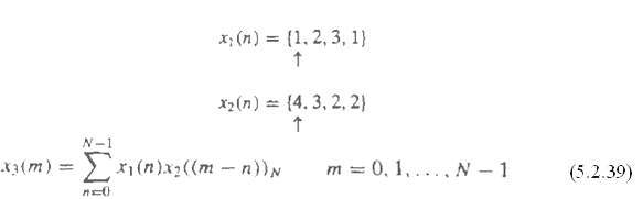
Determine the circular convolution of the Using the time-domain formula in(5.2.39)
Use the four-point DFT and IDFT to determine the sequencewhere x1(n) and x2(n) are the sequence given in problem5.8
Compute the energy of the N-point sequence x(n) = cos 2πkn/N 0 ≤ n ≤ N – 1
Given the eight-point DFT sequence, compute the DFT of thesequence:
Consider a finite-duration sequence (a) Sketch the sequence s (n) with six-point DFT S(k) = W2*X (k) k = 0, 1… 6(b) Determine the sequence y (n) with six-point DFT Y (k) = Re |X (k)|.(c) Determine the sequence v (n) with six-point DFT V (k) = Im
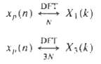
Let xp(n) be a periodic sequence with fundamental period N. Consider the following DFTs: (a) What is the relationship between X1(k) and X3(k)? (b) Verify the result in part (a) using the sequence xp (n) = {. 1, 2, 1, 2, 1, 2, 1, 2 .}
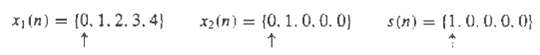
Consider the sequencesand their 5-points DFTs.(a) Determine a sequence y(n) so that Y(k) = X1(k) X2(k).(b) Is there a sequence x3(n) such that S(k) = X1(k)X3(k)
Consider a causal LTI system with system function.The out put y(n) of the system in known for 0 ? n ? 63. Assuming that H(z) is available, can you develop a 64-point DFT method to recover the sequence x(n), 0 ? n ? 63? Can you recover all values of x(n) in this interval?
The impulse response of an LTI system is given by h(n) = δ(n) – ¼δ(n – k0). To determine the impulse response g(n) of the inverse system, an engineer computes the determine N-point DFT H (k), N = 4k0, of h(n) and then defines g(n) as the inverse DFT of G(k) = 1/H(k) = 0, 1, 2 . N –
Determine the eight-point DFT of the signalx(n) = {1, 1, 1, 1, 1, 1, 0, 0}and sketch its magnitude and phase.
Showing 1000 - 1100
of 1744
First
4
5
6
7
8
9
10
11
12
13
14
15
16
17
18
Step by Step Answers