New Semester
Started
Get
50% OFF
Study Help!
--h --m --s
Claim Now
Question Answers
Textbooks
Find textbooks, questions and answers
Oops, something went wrong!
Change your search query and then try again
S
Books
FREE
Study Help
Expert Questions
Accounting
General Management
Mathematics
Finance
Organizational Behaviour
Law
Physics
Operating System
Management Leadership
Sociology
Programming
Marketing
Database
Computer Network
Economics
Textbooks Solutions
Accounting
Managerial Accounting
Management Leadership
Cost Accounting
Statistics
Business Law
Corporate Finance
Finance
Economics
Auditing
Tutors
Online Tutors
Find a Tutor
Hire a Tutor
Become a Tutor
AI Tutor
AI Study Planner
NEW
Sell Books
Search
Search
Sign In
Register
study help
engineering
telecommunication engineering
Digital Signal Processing 3rd Edition Jonh G. Proakis, Dimitris G.Manolakis - Solutions
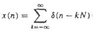
A linear time-invariant system with frequency response H(?) is excited with the periodic input,?suppose that we compute the N-point DFT Y(k) of the samples y(n), 0 ? n ? N ? 1?of the output sequence. How is Y(k) related to H(?)?
DFT if real sequences with special symmetries(a) Using the symmetry properties of section 5.2 (especially the decomposition properties), explain how we can compute the DFT of two real symmetric (even) and two real antisymmetric (odd) sequences simultaneously using an N-point DFT only.(b) Suppose
DFI of real sequences with odd harmonics only Let x(n) be an N-point real sequence with N-point DFT X(k) (N even). In addition, x(n) satisfied the following symmetry property: x(n + N/2) = -x(n) n = 0, 1 … N/2 – 1that is, the upper half of the sequence is the
Let xa(t) be an analog signal with bandwidth B = 3 kHz. We wish to use a N = 2m point DFT to compute the spectrum of the signal with a resolution less than or equal to 50 Hz. Determine (a) The minimum sampling rate, (b) The minimum number of required samples, (c) The minimum length
Consider the periodic sequence xp(n) = cos 2π/10n - ∞ < n < ∞with frequency f0 = 1/10 and fundamental period N = 10. Determine the 10-point DFT of the sequence x(n) = xp(n), 0 ≤ n ≤ N – 1.
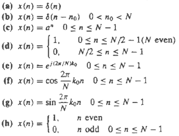
Compute the N-point DFTs of thesignals
Consider the finite-duration signal x(n) = {1, 2, 3, 1}(a) Compute its four-point DFT by solving explicitly the 4-by-4 system of linear equations defined by the inverse DFT formula.(b) Check the answer in part (a) by computing the four-point DFT, using its definition.
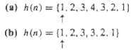
(a) Determine the Fourier transform X(?) of the signal(b) Compute the 6-point DFT V(k) of the signalv(n) = {3, 2, 1, 0, 1, 2}(c) Is there any relation between X(?) and V(k)? Explain.
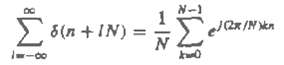
Prove theidentity
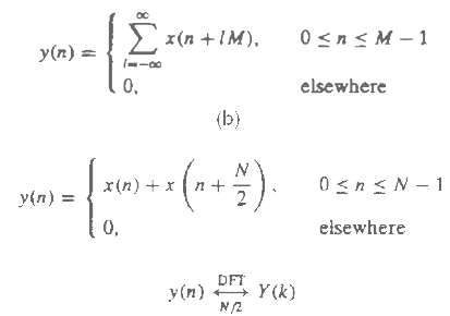
Computation of the even and odd harmonics using the DFT Let x(n) be an N-point sequence with an n-point DFT X(k) (N even) (a) Consider the time-aliased sequence. What is the relationship between the M-point DFT Y(k) of y(n) and the Fourier transform X(?) of x(n)? (b) Let, and show that X(k) =
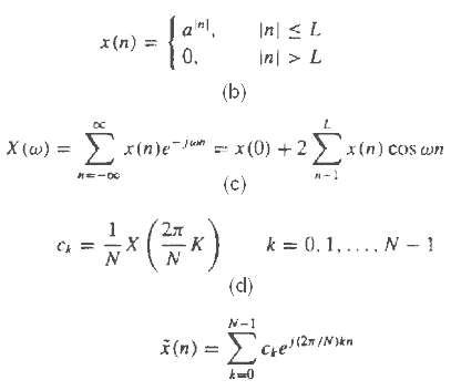
Frequency-domain sampling consider the following discrete-time signal, where a = 0.95 and L = 10.(a) Compute and plot the signal x(n).(b) Show that, Plot X(?) by computing it at ? = ?k/100, k = 0, 1, . . . , 100.(c) Compute, for N = 30.(d) Determine and plot the signal. What is the relation between
Frequency-domain sampling the signal x(n) = a|n|, -1 < a < 1 has a Fourier transform X(ω) = 1 – a2/1 – 2a cosω + a2 (a) Plot X(ω) for 0 ≤ ω ≤ 2π, a = 0.8. Reconstruct and plot X(ω) from its samples X(2πk/N), 0 ≤ k ≤ N – 1 for: (b)
Frequency analysis of amplitude-modulated discrete-time signal the discrete-time signalx(n) = cos2πf1n + cos2πf2nWhere f1 = 1/18 and f2 = 5/128, modulates the amplitude of the carrierx0(n) = cos2πf0nWhere f0 = 50/128. The resulting amplitude-modulated signal is xam(n) = x(n)cos2πf0n(a)
The sawtooth waveform in figure can be expressed in the form of a Fourier series as(a) Determine the Fourier series coefficients ck.(b) Use an N-point subroutine to generates samples of this signal in the time domain using the first six terms of the expansion for N = 64 and N = 128. Plot the signal
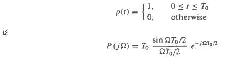
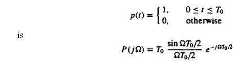
Recall that the Fourier transform of x(t) = ejΩ0 is X(jΩ) = 2πδ(Ω – Ω0) and the Fourier transform of:(a) Determine the Fourier transform Y(jΩ) of Y(t) = p(t)ejΩ0tAnd roughly sketch |Y(jΩ)| versus Ω.(b) Now consider the exponential sequence x(n) = ejω0nwhere ω0 is some
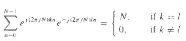
Show that each of the numbers, ej(2?/N)k ?? ? ? ? ? ??0 ? k ? N ? 1 corresponds to an Nth root of unity. Plot these numbers as phasors in the complex plane and illustrate, by means of this figure, the orthogonality property
(a) Show that the phase factors can be computed recursively by. (b) Perform this computing once using single-precision floating-point arithmetic and once using only four significant digits. Note the deterioration due to the accumulation of round-off errors in the later case. (c) Show how the
Let x(n) be a real-valued N-point (N = 2v) sequence. Develop a method to compute an N-point DFT X’(k), which contains only the odd harmonics [i.e., X’(k) = 0 if k is even] by using only a real N/2-spoint DFT.
A designer has available a number of eight-point FFT chips. Show explicitly how he should interconnect three such chips in order to compute a 24-point DFT.
The z-transform o f the sequence x(n) = u(n) – u(n – 7) is sampled at five points on the unit circle as follows x(k) = X(z)|z = ej2πk/5 k = 0, 1, 2, 3, 4 Determine the inverse DFT x’(n) of X(k). Compare it with x(n) and explain the results.
Consider a finite-duration sequence x(n), 0 ≤ n ≤ 7, with z-transform X(z). We wish to compute X(z) at the following set of values: zk = 0.8ej[(2πk/8)+(π/8)] 0 ≤ k ≤ 7 (a) Sketch the points {zk} in the complex plane. (b) Determine a sequence s(n) such that its
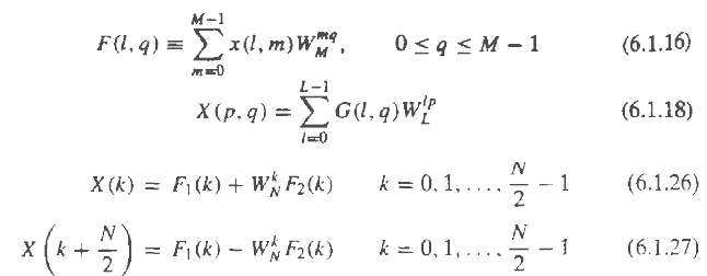
Derive the radix-2 decimation-in-time FFT algorithm given by (6.1.26) and (6.1.27) as a special case of the more general algorithm procedure given by (6.1.16) through(6.1.18).
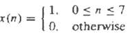
Compute the eight-point DFT of the sequenceby using the decimation-in-frequency FFT algorithm described in thetext.
Derive the signal flow graph for the N = 16 points, radix-4 decimation-in-time FFT algorithm in which the input sequence is in normal order and the computations are done in place.
Derive the signal flow graph for the N = 16 points, radix-4 decimation-in-frequency FFT algorithm in which the input sequence is in digit-reversed order and the output DFT is in normal order.
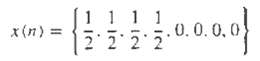
Compute the eight-point DFT of the sequencesusing the in-place radix-2 decimation-in-frequency algorithms. Follow exactly the corresponding signal flow graphs and keep track of all the intermediate quantities by putting them on thediagrams.
Compute the 16-point DFT of the sequence, x(n) = cosπ/2n 0 ≤ n ≤ 15 using he radix-4 decimation-in-time algorithm.
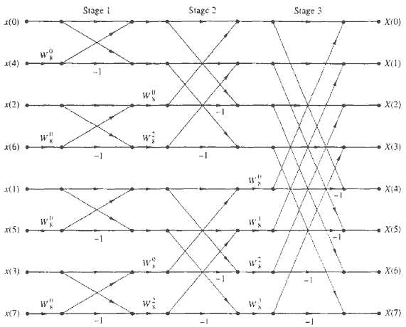
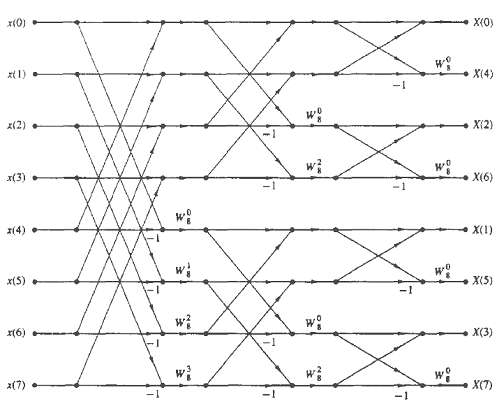
Consider the eight-point decimation-in-time (DTI) flow graph in figure. (a) What is the gain of the ?signal path? that goes from x(7) to X(2)? (b) How many paths leads from the input to a given output sample? Is this true for every output sample? (c) Compute X(3) using the operations dictated by
Draw the flow graph for the decimation-in-frequency (DIF) SREET algorithm for N = 16. What is the number of nontrivial multiplications?
Derive the algorithm and draw the N = 8 flow graph for the DIT SRFFT algorithm. Compare your flow graph with the DIF radix-2 FFT flow graph shown infigure.
Show that the product of two complex numbers (a + jb) and (c + jd) can be performed with three real multiplication and five additions using the algorithmxR = (a – b)d + (c – d)ax1 = (a – b)d + (c + d)bWherex = xR + jx1 = (a + jb)(c + jd)
Explain how the DFT can be used to compute N equispaced samples of the z-transform, of an N-point sequence, on a circle of radius r.
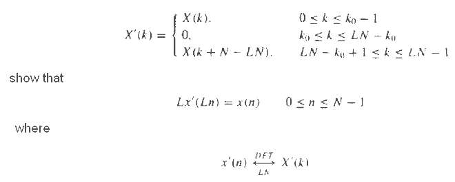
A real-valued N-point sequence x(n) is called DFT bandlimited if its DFT X(k) = 0 for k0 ? k ? N ? k0. We insert (L ? 1)N zeros in the middle of X(k) to obtain the following LN-point DFT Explain the meaning of this type of processing by working out an example with N = 4, L = 1, and X(k) = {1, 0,
Let X(k) be the N-point DFT of the sequence x(n), 0 ≤ n ≤ A’ – 1. What is the N-point DFT of the sequence s(n) = X(n), 0 ≤ n ≤ N – 1?
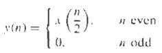
Let X(k) be the N-point DFT of the sequence x(n), 0 ? n ? N ? 1. We define a 2N-point sequence y(n) as,? Express the 2N-point DFT of y(n) in terms of X(k).
(a) Determine the z-transform W(z) of the Hanning window ω(n) = (1 – cos2πn/N-1)/2. (b) Determine a formula to compute the N-point DFT Xω(k) of the signal xw(n) = ω(n)x(n), 0 ≤ n ≤ N – 1, from the N-point DFT X(k) of the signal x(n).
Create a DFT coefficient table that uses only N/4 memory locations to store the first quadrant of the sine sequence (assume N even).
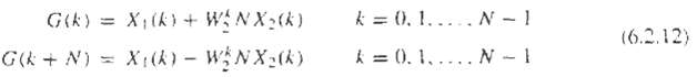
Determine the computation burden of he algorithm given by (6.2.12) and compare it with the computational burden required in the 2N-point DFT of g(n). Assume that the FFT algorithm is radix-2algorithm.
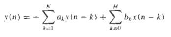
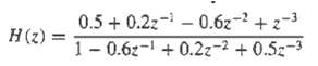
Consider an IIR system described by the difference equation. Described a procedure that computes the frequency response H(2?/n k). k = 0, 1 . . . N ? 1 using the FFT algorithm (N = 2v).
Develop a radix-3 decimation-in-time FFT algorithm for N = 3v and draw the corresponding flow graph for N = 9. What is the number of required complex multiplications? Can the operations be performed in place?
Repeat problem 6.25 for the DIF case.Develop a radix-3 decimation-in-time FFT algorithm for N = 3' and draw the corresponding flow graph for N = 9. What is the number of required complex multiplication? Can the operation be performed in place?
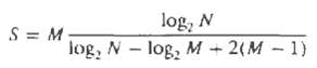
FFT input and output pruning in many applications we wish to compute only a few points M of the N-point DFT of a finite-duration sequence of length L (i.e., M
Parallel computation of the DFT suppose that we wish to compute an N = 2p2v points DFT using 2p digital signal processors (DSPs). For simplicity we assume that p = v = 2. In this case each DSP carries out all the computations that are necessary to compute 2v DFT points.(a) Using the radix-2 DIF
Develop an inverse radix-2 DIR FFT algorithm starting with the definition. Draw the flow graph for computation and compare with the corresponding flow graph for the direct FFT. Can the IFFT flow graph be obtained from the one for the direct FFT?
Refer problem 6.29 for the DIF case.Develop an inverse redix-2 DIT FFT algorithm starting with the definition. Draw the flow graph for computation and compare with the corresponding flow graph for the direct FFT. Can the IFFT flow graph be obtained from the one for the direct FFT?
Show that an FFT on data with Hermitian symmetry can be derived by reversing the flow graph of an FFT for real data.
Determine the system function H(z) and the difference equation for the system that uses the Goertzel algorithm to compute the DFT value (N – k)
(a) Suppose that x(n) is a finite-duration sequence of N = 1024 points. It is desired to evaluate the z-transform X(z) of the sequence at the pointszk = ej(2π/1024)k k = 0, 100, 200, . . . , 1000by using the most efficient method or algorithm possible. Describe an algorithm for performing this
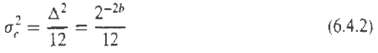
Repeat the analysis for the variance of the quantization error, carried out in section 6.4.2, for the decimation-in-frequency radix-2 FFTalgorithm.
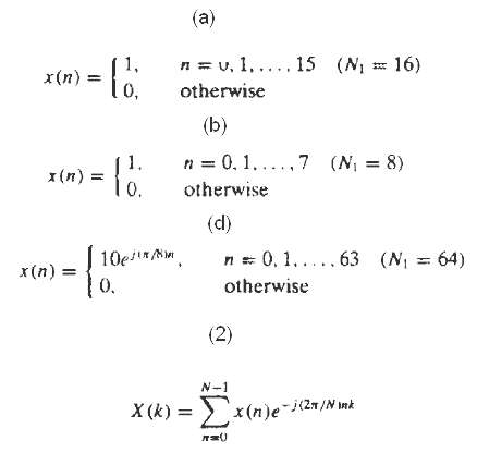
Computation of the DFT use an FFT subroutine to compute the following DFTs and plot the magnitudes |X(k)| of the DFTs. (a) The 64-point DFT of the sequence (b) The 64-point DFT of the sequence (c) The 18-point DFT of the sequence in part (a). (d) The 64-point DFT of the sequence Answer the
Identification of pole positions in a system consider the system described by the difference equation y(n) = -r2y(n – 2) + x(n) (a) Let r = 0.9 and x(n) = δ(n). Generate the output sequence y(n) for 0 ≤ n ≤ 127. Compute the N = 128 point DFT {Y(k)} and {|Y(k)|}. (b) Compute
Determine a direct form realization for the following linear phasefilters.
Consider an FIR filter with system function H(z) = 1 + 2.88z-1 + 3.404z-2 + 1.74z-3 + 0.4z-4Sketch the direct form and lattice realizations of the filter and determine in detail the corresponding input-output equations. Is the system minimum phase?
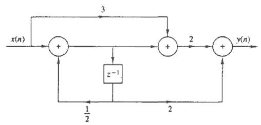
Determine the system function and the impulse response of the system shown inFigure
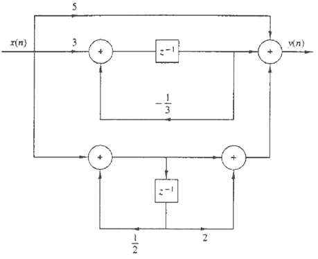
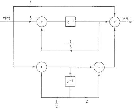
Determine the system function and the impulse response of the system shown infigure
Determine the transposed structure of the systems in figure and verify that both the original and the transposed system have the same systemfunction.
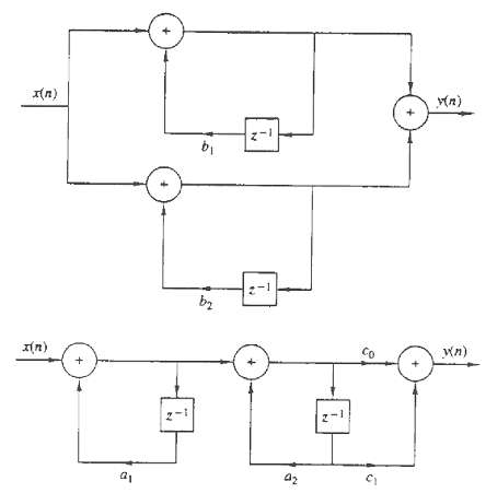
Determine a1, a2, and c1 and c0 in terms of b1 and b2 so that the two systems in figure areequivalent.
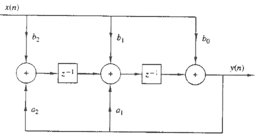
Consider the filter shown in figure(a) Determine its system function.(b) Sketch the pole-zero plot and check for stability if(1) b0 = b2 = 1, b1 = 2, a1 = 1.5, a2 = - 0.9(2) b0 = b2 = 1, b1 = 2,
Consider an LTI system, initially at rest, described by the difference equationy(n) = ¼y(n – 2) + x(n)(a) Determine the impulse response, h(n), of the system.(b) What is the response of the system to the input signalx(n) = [(1/2)n + (-1/2)n]u(n)(c) Determine the direct form II, parallel-form,
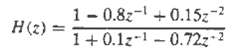
Obtain the direct form I, direct form II, cascade, and parallel structure for the following systems.(a) y(n) = 3/4y(n – 1) – 1/8y(n – 2) + x(n) + 1/3x(n – 1)(b) y(n) = -0.1y(n – 1) + 0.72y(n – 2) + 0.7x(n) – 0.252x(n – 2)(c) y(n) = -0.1y(n – 1) + 0.2y(n – 2) + 3x(n) + 3.6x(n –
Show that the system in figure isequivalent.
Determine all the FIR filters which are specified by the lattice parameters K1 = ½, K2 = 0.6, K3 = -0.7, and K4 = 1/3
Determine the set of difference the set of difference equations for describing a realization of an IIR system based on the use of the transposed direct form II structure for the second order subsystems.
Write a program that implement a parallel-form realization based on transposed direct form II second-order modules.
Write a program that implements a cascade-form realization based on regular direct form II second-order modules.
Determine the parameters {Km} of the lattice filter corresponding to the FIR filter described by the system functionH(z) = A2(z) = 1 + 2z –1 + z –2
(a) Determine the zeros and sketch the zero pattern for the FIR lattice filter with parametersK1 = ½, K2 = -1/3, K3 = 1(b) The same as in part (a) but with K3 = -1.(c) You should have found that all the zeros lie exactly on the unit circle. Can this result be generalized? How?(d) Sketch the
Consider an FIR lattice filter with coefficients K1 = 0.65, K2 = –0.34 and K3 = 0.8.(a) Find its impulse response by tracing a unit impulse input through the lattice structure.(b) Draw the equivalent direct-form structure.
Consider a causal IIR system with system function(a) Determination the equivalent lattice-ladder structure.(b) Check if the system isstable.
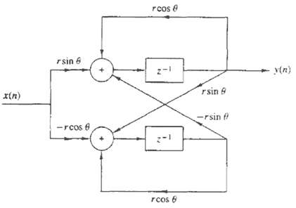
Determine the input-output relationship, the system function, and plot the pole-zero pattern for the discrete-time system shown infigure.
Determine the coupled-form state-space realization for the digitalresonator
(a) Determine the impulse response of an FIR lattice filter with parameters K1 = 0.6, K2 = 0.3, K3 = 0.5, and K4 = 0.9.(b) Sketch the direct form and lattice all-zero and all-pole filters specified by the K – parameters given in part (a).
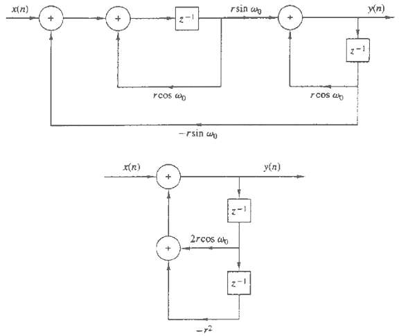
(a) Sketch the lattice realization for the resonator H(z) = 1/1-(2rcosω0)z-1 + r2z –2 (b) What happens if r = 1?
Sketch the lattice-ladder structure for thesystem
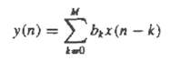
Determine a state-space model and the corresponding realization for the following FIRsystem:
Determine the state-space model for the system described by y(n) = y(n – 1) + 0.11y(n – 2) + x(n)and sketch the type 1 and 2 state-space realizations.
Determine the type 1 and type 2 state-space realizations for the Fibonacci system and its diagonal form.
By means of the z-transform, determine the impulse response of the system described by the state-spaceparameters
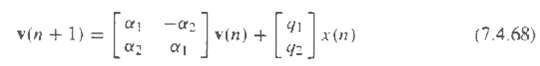
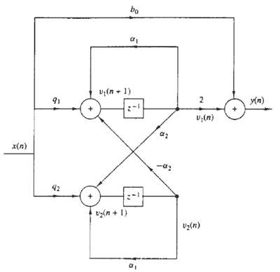
Determine the characteristic polynomial of the coupled-form state-space structure described by (7.4.68) and solve for theroots.
Determine the transpose structure for the coupled-form state-space structure shown infigure
Consider a pole-zero system with system function.(a) Sketch the regular and transpose direct form II realization of the system.(b) Determine and sketch the type 1 and type 2 state-space realizations.(c) Determine the impulse response of the system by inverting H(z) and by using state-space
(a) Determine a parallel and a cascade realization of the system (b) Determine the type 1 and type 2 state-space descriptions of the system in part(a).
Show how to use a lattice structure to implement the following all-pass filter.Is the systemstable?
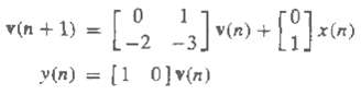
Consider a system described by the following state-space equations:(a) Determine the characteristic polynomial and the eigenvalues of the system.(b) Determine the state transition matrix ?(n) for n ? 0.(c) Determine the system function and the impulse response of the system.(d) Compute the step
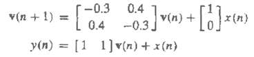
Repeat problem 7.33 if the system is described by the state-spaceequations
Repeat problem 7.33 for the system described by the state-spaceequations
Consider the systemy(n) = 0.9y(n – 1) – 0.08y(n – 2) + x(n) + x(n – 1)(a) Determine the type 1 and type 2 state-space realizations of the system.(b) Determine the parallel and cascade state-space realizations of the system.(c) Determine the impulse response of the system by at least two
Consider the causal system y(n) = ¾y(n – 1) – 1/8y(n – 2) + x(n) + 1/3x(n – 1) (a) Determine its system function. (b) Determine the type 1 state-space model. (c) Determine the state transition matrix Φ{n} = Fn, for any n, using z-transform techniques. (d) Determine the system
Determine the impulse response of the system using the z ?? transformapproach.
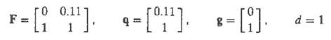
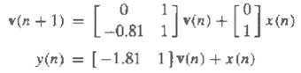
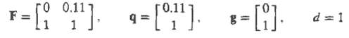
A discrete-time system is described by the following state-space model:v(n + 1) = Fv(n) + qx(n)y(n) = gtv(n) + dx(n)where(a) Sketch the corresponding state-space structure.(b) Calculate the impulse response for n + 0, 1 . . . . 5 and for n = 17 by using the state-space approach.(c) Find the
Determine the state-space parameters F, q, g, and d for:(a) The all-zero lattice structure.(b) The all-pole lattice structure.
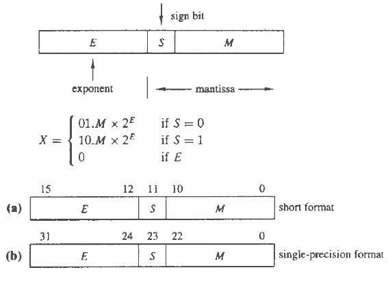
The generic floating-points format for a DSP microprocessor is the following:The value of the number X is given by is the most negative two’s-complex value.Determine the range of positive and negative number for the following two formats:
Consider the IIR recursive filter shown in figure and let hF(n), hR(n), and h(n) denote the impulse responses of the FIR section, the recursive section, and the overall filter, respectively. (a) Find all the causal and stable recursive second-order sections with integer coefficients (a1, a2) and
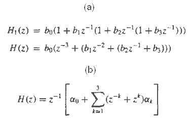
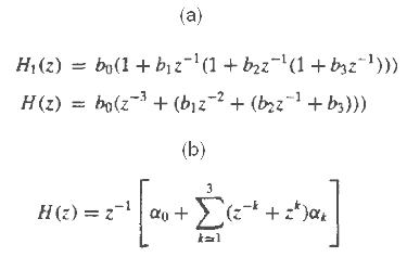
This problem illustrates the development of digital filter structures using Horner?s rule for polynomial evaluation. To this end consider the polynomial, p(x) = apxp + ap-1xp-1 + . . . + a1x + a0 which computes p(x) with the minimum cost of p multiplications and p additions. (a) Draw the structures
Let x1 and x2 be (b + 1)- bit binary numbers with magnitude less than 1. To compute the sum of x1 and x2 using two’s-complements representation we treat them as (b + 1)-bit unsigned numbers, we perform addition modulo-2 and ignore any carry after the sign bit.(a) Show that if the sum of two
Consider the system described by the difference equationy(n) = ay(n – 1) – ax(n) + x (n – 1)(a) Show that it is all-pass.(b) Obtain the direct form II realization of the system(c) If you quantize the coefficients of the system in part (b), is it still all-pass?(d) Obtain a realization by
Consider the systemy(n) = ½y(n – 1) 6 x(n)(a) Compute its response to the input x(n) = (1/4)nu(n) assuming infinite-precision arithmetic(b) Compute the response of the system y(n), 0 ≤ n ≤ 5 to the same input, assuming finite-precision sign-and-magnitude fractional arithmetic with five bits
The input to the systemy(n) = 0.999y(n – 1) + x(n)is quantized to b = 8 bits. What is the power produced by the quantization noise at the output of the filter?
Consider the systemy(n) = 0.875y(n – 1) – 0.125y(n – 2) + x(n)(a) Compute its poles and design the cascade realization of the system.(b) Quantize the coefficients of the system using truncation, maintaining a sign bit plus three other bits. Determine the poles of the resulting system. (c)
Showing 1100 - 1200
of 1744
First
4
5
6
7
8
9
10
11
12
13
14
15
16
17
18
Step by Step Answers