New Semester
Started
Get
50% OFF
Study Help!
--h --m --s
Claim Now
Question Answers
Textbooks
Find textbooks, questions and answers
Oops, something went wrong!
Change your search query and then try again
S
Books
FREE
Study Help
Expert Questions
Accounting
General Management
Mathematics
Finance
Organizational Behaviour
Law
Physics
Operating System
Management Leadership
Sociology
Programming
Marketing
Database
Computer Network
Economics
Textbooks Solutions
Accounting
Managerial Accounting
Management Leadership
Cost Accounting
Statistics
Business Law
Corporate Finance
Finance
Economics
Auditing
Tutors
Online Tutors
Find a Tutor
Hire a Tutor
Become a Tutor
AI Tutor
AI Study Planner
NEW
Sell Books
Search
Search
Sign In
Register
study help
computer science
systems analysis design
Power System Analysis And Design 6th Edition J. Duncan Glover, Thomas Overbye, Mulukutla S. Sarma - Solutions
Determine the subtransient fault current in per-unit and in kA, as well as the per-unit line-to-ground voltages at the fault bus for a bolted single line-to-ground fault at the fault bus selected in Problem 9.2.Problem 9.2Faults at bus \(n\) in Problem 9.1 are of interest (the instructor selects
Repeat Problem 9.14 for a single line-to-ground arcing fault with arc impedance \(Z_{\mathrm{F}}=15+j 0 \Omega\).Problem 9.14Determine the subtransient fault current in per-unit and in kA, as well as the per-unit line-to-ground voltages at the fault bus for a bolted single line-to-ground fault at
Repeat Problem 9.14 for a bolted line-to-line fault.Problem 9.14Determine the subtransient fault current in per-unit and in kA, as well as the per-unit line-to-ground voltages at the fault bus for a bolted single line-to-ground fault at the fault bus selected in Problem 9.2.Problem 9.2Faults at bus
Repeat Problem 9.14 for a bolted double line-to-ground fault.Problem 9.14Determine the subtransient fault current in per-unit and in kA, as well as the per-unit line-to-ground voltages at the fault bus for a bolted single line-to-ground fault at the fault bus selected in Problem 9.2.Problem
Repeat Problems 9.1 and 9.14 including \(\Delta-Y\) transformer phase shifts. Assume American standard phase shift. Also calculate the sequence components and phase components of the contribution to the fault current from generator \(n\) ( \(n=1,2\), or 3 as specified by the instructor in Problem
(a) Repeat Problem 9.14 for the case of Problem 9.4 (b).(b) Repeat Problem 9.19 (a) for a single line-to-ground arcing fault with arc impedance \(Z_{\mathrm{F}}=(15+j 0) \Omega\).(c) Repeat Problem 9.19 (a) for a bolted line-to-line fault.(d) Repeat Problem 9.19 (a) for a bolted double
A 500-MVA, 13.8 -kV synchronous generator with \(\mathrm{X}_{d}^{\prime \prime}=\mathrm{X}_{2}=0.20\) and \(\mathrm{X}_{0}=0.05\) per unit is connected to a \(500-\mathrm{MVA}, 13.8 -\mathrm{kV} \Delta / 500-\mathrm{kV}\) \(\mathrm{Y}\) transformer with 0.10 per-unit leakage reactance. The
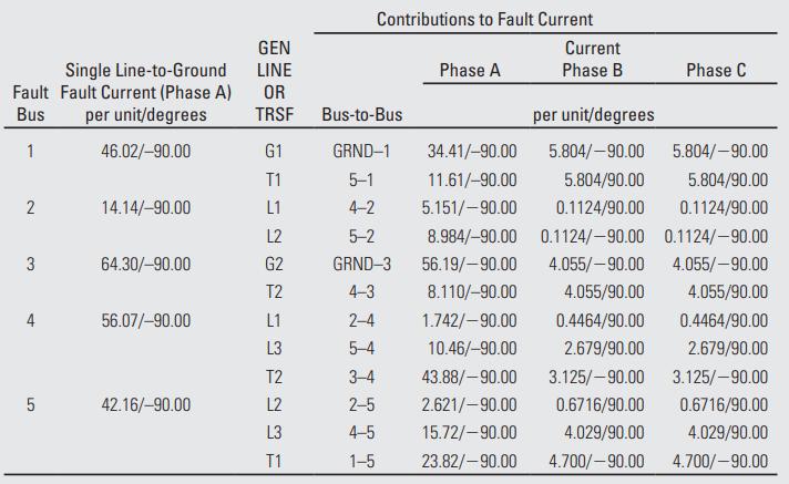
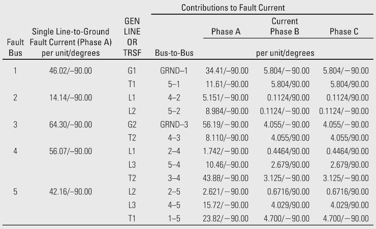
Determine the subtransient fault current in per-unit and in kA, as well as contributions to the fault current from each line and transformer connected to the fault bus for a bolted single line-to-ground fault at the fault bus selected in Problem 9.6.Problem 9.6Faults at bus \(n\) in Problem 9.5 are
Repeat Problem 9.21 for a bolted line-to-line fault.Problem 9.21Determine the subtransient fault current in per-unit and in kA, as well as contributions to the fault current from each line and transformer connected to the fault bus for a bolted single line-to-ground fault at the fault bus selected
Repeat Problem 9.21 for a bolted double line-to-ground fault.Problem 9.21Determine the subtransient fault current in per-unit and in kA, as well as contributions to the fault current from each line and transformer connected to the fault bus for a bolted single line-to-ground fault at the fault bus
Determine the subtransient fault current in per-unit and in \(\mathrm{kA}\), as well as contributions to the fault current from each line, transformer, and generator connected to the fault bus for a bolted single line-to-ground fault at the fault bus selected in Problem 9.9.Problem 9.9Faults at bus
Repeat Problem 9.24 for a single line-to-ground arcing fault with arc impedance \(Z_{\mathrm{F}}=0+j 0.1 \) per unit.Problem 9.24Determine the subtransient fault current in per-unit and in \(\mathrm{kA}\), as well as contributions to the fault current from each line, transformer, and generator
Repeat Problem 9.24 for a bolted line-to-line fault.Problem 9.24Determine the subtransient fault current in per-unit and in \(\mathrm{kA}\), as well as contributions to the fault current from each line, transformer, and generator connected to the fault bus for a bolted single line-to-ground fault
Repeat Problem 9.24 for a bolted double line-to-ground fault.Problem 9.24Determine the subtransient fault current in per-unit and in \(\mathrm{kA}\), as well as contributions to the fault current from each line, transformer, and generator connected to the fault bus for a bolted single
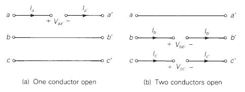
As shown in Figure 9.21 (a), two three-phase buses \(a b c\) and \(a^{\prime} b^{\prime} c^{\prime}\) are interconnected by short circuits between phases \(b\) and \(b^{\prime}\) and between \(c\) and \(c^{\prime}\), with an open circuit between phases \(a\) and \(a^{\prime}\). The fault conditions
Repeat Problem 9.28 for the two-conductors-open fault shown in Figure 9.21 (b). The fault conditions in the phase domain are \[ I_{b}=I_{b^{\prime}}=I_{c}=I_{c^{\prime}}=0 \text { and } V_{a a^{\prime}}=0 \]Problem 9.28As shown in Figure 9.21(a), two three-phase buses \(a b c\) and \(a^{\prime}
For the system of Problem 9.11, compute the fault current and voltages at the fault for the following faults at point \(\mathrm{F}\) :(a) a bolted single line-to-ground fault;(b) a line-to-line fault through a fault impedance \(Z_{\mathrm{F}}=j 0.05 \) per unit;(c) a double line-to-ground fault
For the system of Problem 9.12, compute the fault current and voltages at the fault for the following faults at bus 3:(a) a bolted single line-toground fault,(b) a bolted line-to-line fault,(c) a bolted double line-toground fault. Also, for the single line-to-ground fault at bus 3, determine the
For the system of Problem 9.13, compute the fault current for the following faults at bus 3:(a) a single line-to-ground fault through a fault impedance \(Z_{\mathrm{F}}=j 0.1 \) per unit,(b) a line-to-line fault through a fault impedance \(Z_{\mathrm{F}}=j 0.1 \) per unit,(c) a double
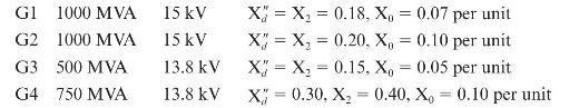
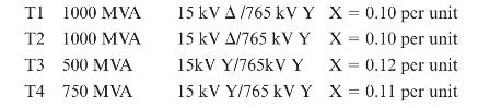
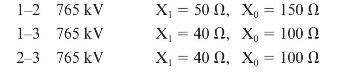
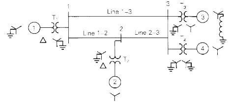
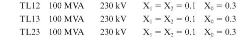
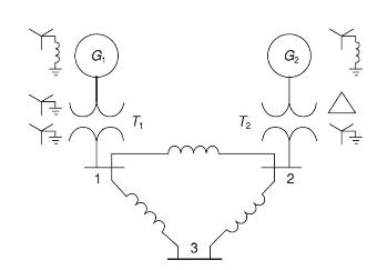
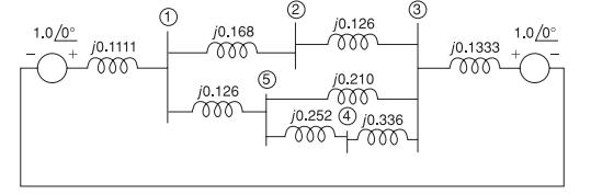
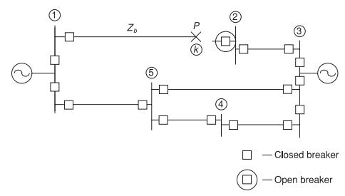
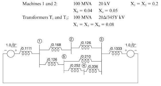
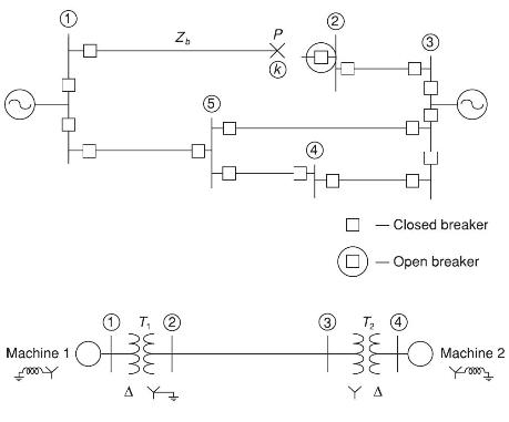
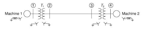
For the three-phase power system with single-line diagram shown in Figure 9.22, equipment ratings and per-unit reactances are given as follows:Machines 1 and 2: \(\quad 100\) MVA \(20 \mathrm{kV} \quad \mathrm{X}_{1}=\mathrm{X}_{2}=0.2\) \[ \mathrm{X}_{0}=0.04 \quad \mathrm{X}_{n}=0.04
At the general three-phase bus shown in Figure 9.7 (a) of the text, consider a simultaneous single line-to-ground fault on phase \(a\) and lineto-line fault between phases \(b\) and \(c\), with no fault impedances. Obtain the sequence-network interconnection satisfying the current and voltage
Thévenin equivalent sequence networks looking into the faulted bus of a power system are given with \(Z_{1}=j 0.15, Z_{2}=j 0.15, Z_{0}=j 0.2\), and \(E_{1}=1 \angle 0^{\circ}\) per unit. Compute the fault currents and voltages for the following faults occurring at the faulted bus:(a) Balanced
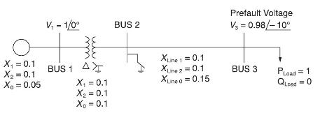
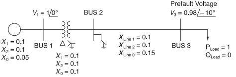
The single-line diagram of a simple power system is shown in Figure 9.23 with per unit values. Determine the fault current at bus 2 for a three-phase fault. Ignore the effect of phase shift.Figure 9.23 O X = 0.1 X = 0.1 Xo = 0.05 V = 1/0 ww 38 BUS 1 A X = 0.1 X = 0.1 X = 0.1 BUS 2 Xune 1 = 0.1 Xune
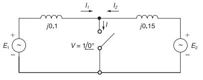
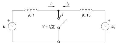
Consider a simple circuit configuration shown in Figure 9.24 to calculate the fault currents \(I_{1}, I_{2}\), and \(I\) with the switch closed.(a) Compute \(E_{1}\) and \(E_{2}\) prior to the fault based on the prefault voltage \(V=1 \angle 0^{\circ}\) and then, with the switch closed, determine
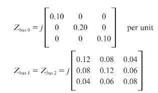
The zero-, positive-, and negative-sequence bus impedance matrices for a three-bus three-phase power system areDetermine the per-unit fault current and per-unit voltage at bus 2 for a bolted three-phase fault at bus 1 . The prefault voltage is 1.0 per unit. j0.1 v = 1/0 j0.15 E
Repeat Problem 9.38 for a bolted single line-to-ground fault at bus 1.Problem 9.38The zero-, positive-, and negative-sequence bus impedance matrices for a three-bus three-phase power system areDetermine the per-unit fault current and per-unit voltage at bus 2 for a bolted three-phase fault at bus 1
Repeat Problem 9.38 for a bolted line-to-line fault at bus 1.Problem 9.38The zero-, positive-, and negative-sequence bus impedance matrices for a three-bus three-phase power system areDetermine the per-unit fault current and per-unit voltage at bus 2 for a bolted three-phase fault at bus 1 . The
Repeat Problem 9.38 for a bolted double line-to-ground fault at bus 1.Problem 9.38The zero-, positive-, and negative-sequence bus impedance matrices for a three-bus three-phase power system areDetermine the per-unit fault current and per-unit voltage at bus 2 for a bolted three-phase fault at bus 1
(a) Compute the \(3 \times 3\) per-unit zero-, positive-, and negative-sequence bus impedance matrices for the power system given in Problem 9.1. Use a base of \(1000 \mathrm{MVA}\) and \(765 \mathrm{kV}\) in the zone of line 1-2.(b) Using the bus impedance matrices.Problem 9.1The single-line
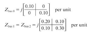
The zero-, positive-, and negative-sequence bus impedance matrices for a two-bus three-phase power system areDetermine the per-unit fault current and per-unit voltage at bus 2 for a bolted three-phase fault at bus 1 . The prefault voltage is 1.03 per unit. Zbus 0 [0.10 0 Zbus 1 = Zbus 2 = j 0 0.10
Repeat Problem 9.43 for a bolted single line-to-ground fault at bus 1.Problem 9.43The zero-, positive-, and negative-sequence bus impedance matrices for a two-bus three-phase power system areDetermine the per-unit fault current and per-unit voltage at bus 2 for a bolted three-phase fault at bus 1 .
Repeat Problem 9.43 for a bolted line-to-line fault at bus 1.Problem 9.43The zero-, positive-, and negative-sequence bus impedance matrices for a two-bus three-phase power system areDetermine the per-unit fault current and per-unit voltage at bus 2 for a bolted three-phase fault at bus 1 . The
Repeat Problem 9.43 for a bolted double line-to-ground fault at bus 1.Problem 9.43The zero-, positive-, and negative-sequence bus impedance matrices for a two-bus three-phase power system areDetermine the per-unit fault current and per-unit voltage at bus 2 for a bolted three-phase fault at bus 1 .
Compute the \(3 \times 3\) per-unit zero-, positive-, and negative-sequence bus impedance matrices for the power system given in Problem 4(a). Use a base of \(1000 \mathrm{MVA}\) and \(500 \mathrm{kV}\) in the zone of line 1-2.Problem 4In Problem 9.1 and Figure 9.17, let \(765 \mathrm{kV}\) be
Using the bus impedance matrices determined in Problem 9.47.Problem 9.47Compute the \(3 \times 3\) per-unit zero-, positive-, and negative-sequence bus impedance matrices for the power system given in Problem 4(a). Use a base of \(1000 \mathrm{MVA}\) and \(500 \mathrm{kV}\) in the zone of line
Compute the \(4 \times 4\) per-unit zero-, positive-, and negative-sequence bus impedance matrices for the power system given in Problem 9.5. Use a base of \(1000 \mathrm{MVA}\) and \(20 \mathrm{kV}\) in the zone of generator G3.Problem 9.5Equipment ratings for the four-bus power system shown in
Using the bus impedance matrices determined in Problem 9.42.Problem 9.42(a) Compute the \(3 \times 3\) per-unit zero-, positive-, and negative-sequence bus impedance matrices for the power system given in Problem 9.1. Use a base of \(1000 \mathrm{MVA}\) and \(765 \mathrm{kV}\) in the zone of line
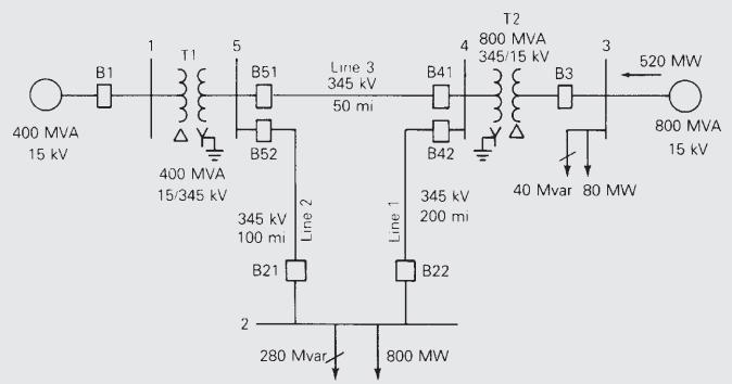
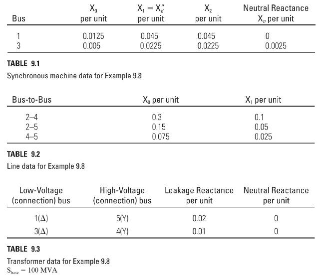
Compute the \(5 \times 5\) per-unit zero-, positive-, and negative-sequence bus impedance matrices for the power system given in Problem 9.8. Use a base of 100 MVA and \(15 \mathrm{kV}\) in the zone of generator G2.Problem 9.8Equipment ratings for the five-bus power system shown in Figure 7.15 are
Using the bus impedance matrices determined in Problem 9.51.Problem 9.51Compute the \(5 \times 5\) per-unit zero-, positive-, and negative-sequence bus impedance matrices for the power system given in Problem 9.8. Use a base of 100 MVA and \(15 \mathrm{kV}\) in the zone of generator G2.Problem
The positive-sequence impedance diagram of a five-bus network with all values in per-unit on a 100-MVA base is shown in Figure 9.25. The generators at buses 1 and 3 are rated 270 and 225 MVA, respectively. Generator reactances include subtransient values plus reactances of the transformers
For the five-bus network shown in Figure 9.25, a bolted single-line-toground fault occurs at the bus 2 end of the transmission line between buses 1 and 2. The fault causes the circuit breaker at the bus 2 end of the line to open, but all other breakers remain closed. The fault is shown in Figure
A single-line diagram of a four-bus system is shown in Figure 9.27 . Equipment ratings and per-unit reactances are given as follows.On a base of \(100 \mathrm{MVA}\) and \(345 \mathrm{kV}\) in the zone of the transmission line, the series reactances of the transmission line are \(X_{1}=X_{2}=0.15\)
The system shown in Figure 9.28 except that the transformers are now \(\mathrm{Y}-\mathrm{Y}\) connected and solidly grounded on both sides. (a) Determine the bus impedance matrix for each of the three sequence networks. (b) Assume the system to be operating at nominal system voltage without
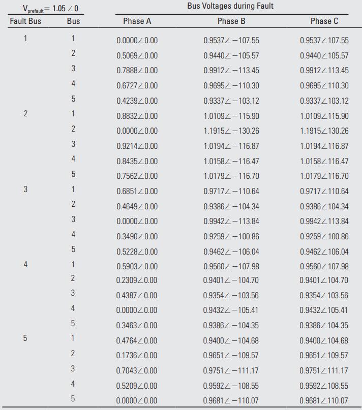
The results in Table 9.5 show that during a phase \(a\) single line-to-ground fault the phase angle on phase \(a\) voltages is always zero. Explain why we would expect this result.Table 9.5 Vprefault=1.05 20 Bus Fault Bus 1 2 3 4 01 5 1 2 3 st 4 5 1 2 3 4 1 2 3 4 5 1 2 3 4 5 1 2 3 4 5 Phase A
The results in Table 9.5 show that during the single line-to-ground fault at bus 2 the \(b\) and \(c\) phase voltage magnitudes at bus 2 actually rise above the prefault voltage of 1.05 per unit. Use PowerWorld Simulator with case Example 9_8 to determine the type of in-line fault midway between
Plot the variation in the bus 2 phase \ (a, b, c\) voltage magnitudes during a single line-to-ground fault at bus 2 as the fault reactance is varied from 0 to 0.30 per unit in 0.05 per-unit steps the fault impedance is specified on the Fault Options page of the Fault Analysis dialog.
Determine the fault current in amps, except with a line-to-line fault at each of the buses. Compare the fault currents with the values given in Table 9.4.Table 9.4 Single Line-to-Ground Fault Fault Current (Phase A) Bus per unit/degrees 1 46.02/-90.00 2 3 4 5 14.14/-90.00 64.30/-90.00 56.07/-90.00
Determine the fault current in amps, except with a bolted double line-to-ground fault at each of the buses. Compare the fault currents with the values given in Table 9.4.Table 9.4 Single Line-to-Ground Fault Fault Current (Phase A) Bus per unit/degrees 1 46.02/-90.00 2 3 4 5 14.14/-90.00
Re-determine the Example 9_8 fault currents, except with a new line installed between buses 2 and 5. The parameters for this new line should be identical to those of the existing line between buses 2 and 5 . The new line is not mutually coupled to any other line. Are the fault currents larger or
Re-determine the Example 9_8 fault currents, except with a second generator added at bus 3. The parameters for the new generator should be identical to those of the existing generator at bus 3. Are the fault currents larger or smaller than the Example 9_8 values?Example 9_8Consider the five-bus
Using PowerWorld Simulator case, calculate the perunit fault current and the current supplied by each of the generators for a single line-to-ground fault at the ORANGE69 bus. During the fault, what percentage of buses have voltage magnitude below per unit?
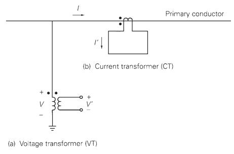
The primary conductor in Figure 10.2 is one phase of a three-phase transmission line operating at \(345 \mathrm{kV}, 700 \mathrm{MVA}, 0.95\) power factor lagging. The CT ratio is \(1200: 5\), and the VT ratio is 3000:1. Determine the CT secondary current \(I^{\prime}\) and the VT secondary voltage
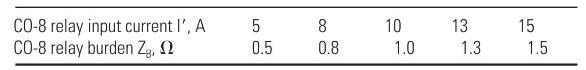
A CO-8 relay with a current tap setting of 5 amperes is used with the 100:5 CT in Example 10.1. The CT secondary current I' is the input to the relay operating coil. The CO-8 relay burden is shown in the following table for various relay input currents.Primary current and CT error are computed in
An overcurrent relay set to operate at \(10 \mathrm{~A}\) is connected to the \(\mathrm{CT}\) in Figure 10.8 with a 500:5 CT ratio. Determine the minimum primary fault current that the relay will detect if the burden \(\mathrm{Z}_{\mathrm{B}}\) is (a) \(1.0 \Omega\), (b) \(4.0 \Omega\), and (c)
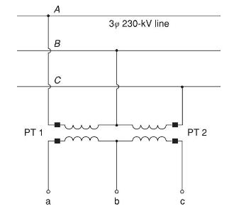
Given the open-delta VT connection shown in Figure 10.38, both VTs having a voltage rating of \(240 \mathrm{kV}: 120 \mathrm{~V}\), the voltages are specified as \(V_{\mathrm{AB}}=230 \angle 0^{\circ}, V_{\mathrm{BC}}=230 \angle-120^{\circ}\), and \(V_{\mathrm{CA}}=230 \angle 120^{\circ}
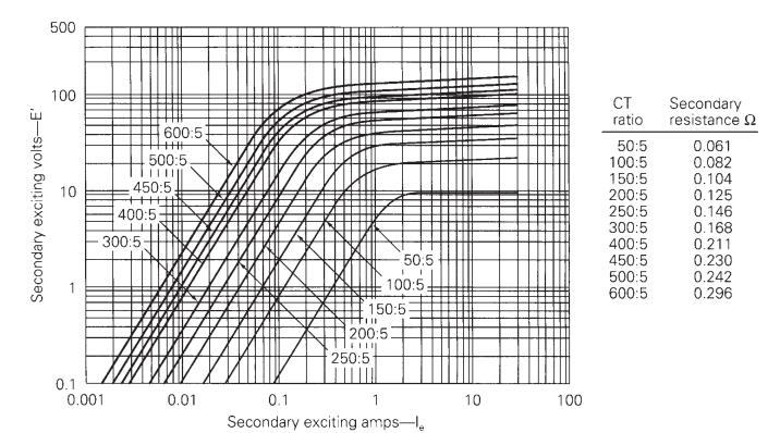
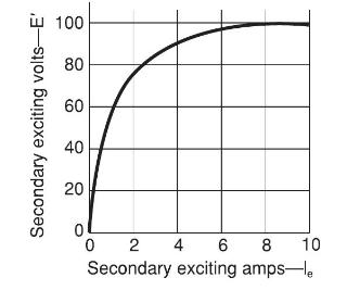
A CT with an excitation curve given in Figure 10.39 has a rated current ratio of 500:5 A and a secondary leakage impedance of \(0.1+j 0.5 \Omega\). Calculate the CT secondary output current and the CT error for the following cases: (a) The impedance of the terminating device is \(4.9+j 0.5 \Omega\)
The CT of Problem 10.5 is utilized in conjunction with a currentsensitive device that will operate at current levels of \(8 \mathrm{~A}\) or above. Check whether the device will detect the 1300-A fault current for cases (b) and (d) in Problem 10.5.Problem 10.5A CT with an excitation curve given in
The input current to a CO-8 relay is \(10 \mathrm{~A}\). Determine the relay operating time for the following current tap settings (TS) and time dial settings (TDS): (a) \(\mathrm{TS}=1.0, \mathrm{TDS}=1 / 2\); (b) \(\mathrm{TS}=2.0, \mathrm{TDS}=1.5\); (c) \(\mathrm{TS}=2.0\), \(\mathrm{TDS}=7\);
The relay in Problem 10.2 has a time-dial setting of 4 . Determine the relay operating time if the primary fault current is \(400 \mathrm{~A}\).Problem 10.2A CO-8 relay with a current tap setting of 5 amperes is used with the 100:5 CT in Example 10.1. The CT secondary current I' is the input to the
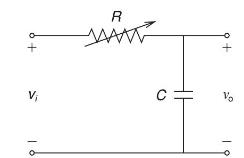
An RC circuit used to produce time delay is shown in Figure 10.40. For a step input voltage \(\mathrm{v}_{\mathrm{i}}(\mathrm{t})=2 \mathrm{u}(\mathrm{t})\) and \(\mathrm{C}=10 \mu \mathrm{F}\), determine \(\mathrm{T}_{\text {delay }}\) for the following cases:(a) \(\mathrm{R}=100 \mathrm{k}
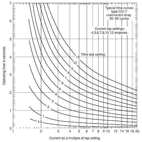
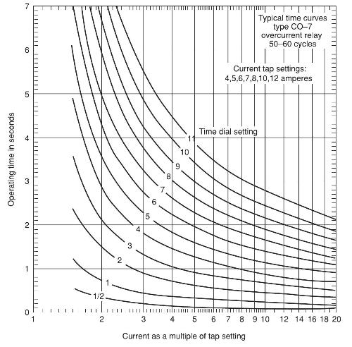
Reconsider case (b) of Problem 10.5. Let the load impedance \(4.9+j 0.5 \Omega\) be the input impedance to a \(\mathrm{CO}-7\) induction disc time-delay overcurrent relay. The CO-7 relay characteristic is shown in Figure 10.41. For a tap setting of \(4 \mathrm{~A}\) and a time dial setting of 2,
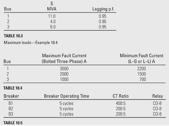
Evaluate relay coordination for the minimum fault currents in Example 10.4. For the selected current tap settings and time dial settings, (a) determine the operating time of relays at B2 and B3 for the 700-A fault current. (b) Determine the operating time of relays at B1 and B2 for the
Repeat Example 10.4 for the following system data. Coordinate the relays for the maximum fault currents.Example 10.4Data for the \(60-\mathrm{Hz}\) radial system of Figure 10.16 are given in Tables 10.3, 10.4, and 10.5. Select current tap settings (TSs) and time-dial settings (TDSs) Bus 1 2 23 3
Using the current tap settings and time dial settings that you have selected in Problem 10.12, evaluate relay coordination for the minimum fault currents. Are the fault-to-pickup current ratios \(\geqslant 2.0\), and are the coordination time delays \(\geqslant 0.3\) seconds in all cases?Problem
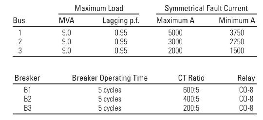
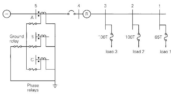
An \(11-\mathrm{kV}\) radial system is shown in Figure 10.42. Assuming a CO-7 relay with relay characteristic given in Figure 10.41 and the same power factor for all loads, select relay settings to protect the system.Figure 10.42Figure 10.41 11 KV 1 3 C.T.R=400/5 132, pq C.T.R=200/5 L3=6.75 MVA
Rework Example 10.5 for the following faults:(a) a threephase, permanent fault on the load side of tap 3;(b) a single line-to-ground, permanent fault at bus 4 on the load side of the recloser; and(c) a three-phase, permanent fault at bus 4 on the source side of the recloser.Example 10.5For the
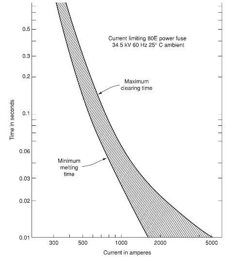
A three-phase \(34.5-\mathrm{kV}\) feeder supplying a 3.5-MVA load is protected by \(80 \mathrm{E}\) power fuses in each phase, in series with a recloser. The time-current characteristic of the 80E fuse is shown in Figure 10.43. Analysis yields maximum and minimum fault currents of 1000 and \(500
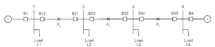
For the system shown in Figure 10.44, directional overcurrent relays are used at breakers B12, B21, B23, B32, B34, and B43. Overcurrent relays alone are used at \(\mathrm{B} 1\) and \(\mathrm{B} 4\).(a) For a fault at \(\mathrm{P}_{1}\), which breakers do not operate? Which breakers should be
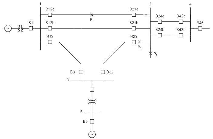
Draw the protective zones for the power system shown in Figure 10.45. Which circuit breakers should open for a fault at(a) \(\mathrm{P}_{1}\),(b) \(\mathrm{P}_{2}\), (c) \(\mathrm{P}_{3}\) ? O 81 B12 B12b R13 3 B31 5 B5 * P. B32 B21a B21b B23 P3 2 B21a 0 B24b 0 ~ B42a B42b 4 B46
Figure 10.46 shows three typical bus arrangements. Although the number of lines connected to each arrangement varies widely in practice, four lines are shown for convenience and comparison. Note that the required number of circuit breakers per line is 1 for the ring bus, \(1 \frac{1}{2}\) for the
Three-zone mho relays are used for transmission line protection of the power system shown in Figure 10.25. Positive-sequence line impedances are given as follows.Rated voltage for the high-voltage buses is \(500 \mathrm{kV}\). Assume a 2500:5 CT ratio and a 4500:1 VT ratio at B12. (a) Determine the
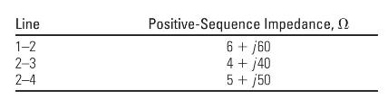
Line impedances for the power system shown in Figure 10.47 are \(Z_{12}=Z_{23}=3.0+j 40.0 \Omega\), and \(Z_{24}=6.0+j 80.0 \Omega\). Reach for the zone 3 B12 impedance relays is set for \(100 \%\) of line \(1-2\) plus \(120 \%\) of line \(2-4\)(a) For a bolted three-phase fault at bus 4, show that
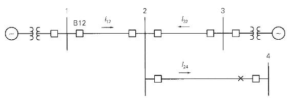
Consider the transmission line shown in Figure 10.48 with series impedance \(Z_{\mathrm{L}}\), negligible shunt admittance, and a load impedance \(Z_{\mathrm{R}}\) at the receiving end. (a) Determine \(Z_{\mathrm{R}}\) for the given conditions of \(\mathrm{V}_{\mathrm{R}}=1.0\) per unit and
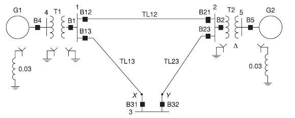
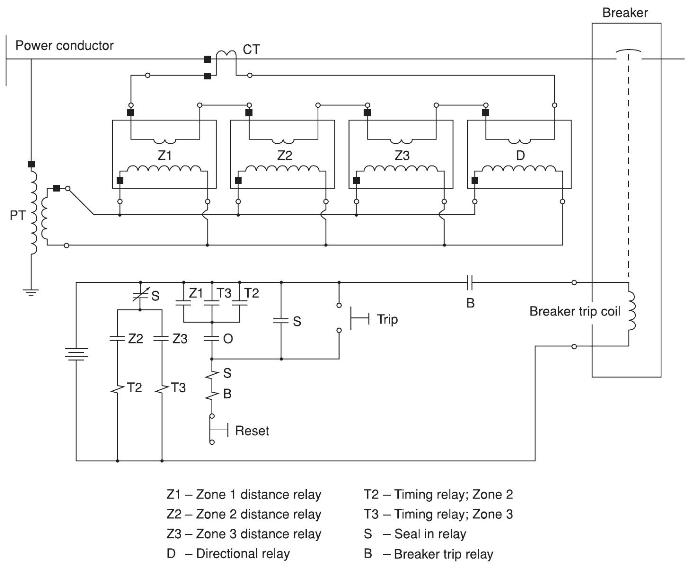
A simple system with circuit breaker-relay locations is shown in Figure 10.49. The six transmission-line circuit breakers are controlled by zone distance and directional relays, as shown in Figure 10.50. The three transmission lines have the same positive-sequence impedance of \(j 0.1\) per unit.
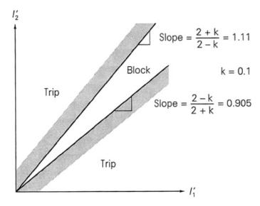
Select \(\mathrm{k}\) such that the differential relay characteristic shown in Figure 10.34 blocks for up to \(20 \%\) mismatch between \(I_{1}^{\prime}\) and \(I_{2}^{\prime}\).Figure 10.34 1/2 Trip Trip Block Slope 2+k 2-k 2-k 2+k Slope - K = 1.11 k = 0.1 = 0.905
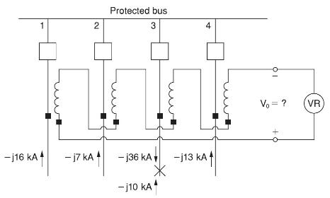
Consider a protected bus that terminates four lines, as shown in Figure 10.51. Assume that the linear couplers have the standard \(X_{m}=5 \mathrm{~m} \Omega\) and a three-phase fault externally located on line 3 causes the fault currents shown in Figure 10.51. Note that the infeed current on line
A single-phase, 5-MVA, 20/8.66-kV transformer is protected by a differential relay with taps. Available relay tap settings are 5:5, 5:5.5, 5:6.6, 5:7.3, 5:8, 5:9, and 5:10, giving tap ratios of 1.00, 1.10, 1.32, 1.46, 1.60, 1.80, and 2.00. Select CT ratios and relay tap settings. Also, determine
A three-phase, \(500-\mathrm{MVA}, 345 \mathrm{kV} \Delta / 500 \mathrm{kV}\) Y transformer is protected by differential relays with taps. Select CT ratios, CT connections, and relay tap settings. Determine the currents in the transformer and in the CTs at rated conditions. Also determine the
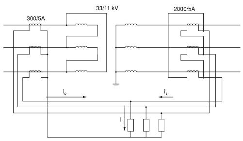
For a \(\Delta\)-Y connected, 15-MVA, \(33: 11 \mathrm{kV}\) transformer with differential relay protection and \(\mathrm{CT}\) ratios shown in Figure 10.52, determine the relay currents at full load and calculate the minimum relay current setting to allow \(125 \%\) overload. 300/5A ip 33/11 kV
Consider a three-phase \(\Delta-Y\) connected, \(30-\mathrm{MVA}, 33: 11 \mathrm{kV}\) transformer with differential relay protection. If the CT ratios are 500:5 A on the primary side and 2000:5 A on the secondary side, compute the relay current setting for faults drawing up to \(200 \%\) of rated
Determine the CT ratios for differential protection of a three-phase, \(\Delta-\mathrm{Y}\) connected, 10-MVA, \(33: 11 \mathrm{kV}\) transformer, such that the circulating current in the transformer \(\Delta\) does not exceed \(5 \mathrm{~A}\).
A three-phase, \(60-\mathrm{Hz}, 500-\mathrm{MVA}, 11.8-\mathrm{kV}\), 4-pole steam turbine-generating unit has an \(\mathrm{H}\) constant of 5 p.u.-s. Determine:(a) \(\omega_{\text {syn }}\) and \(\omega_{m \text { syn }}\);(b) the kinetic energy in joules stored in the rotating masses at
Calculate \(\mathrm{J}\) in \(\mathrm{kg}-\mathrm{m}^{2}\) for the generating unit given in Problem 11.1.Problem 11.1A three-phase, \(60-\mathrm{Hz}, 500-\mathrm{MVA}, 11.8-\mathrm{kV}\), 4-pole steam turbine-generating unit has an \(\mathrm{H}\) constant of 5 p.u.-s. Determine: (a) \(\omega_{\text
Generator manufacturers often use the term \(\mathrm{WR}^{2}\), which is the weight in pounds of all the rotating parts of a generating unit (including the prime mover) multiplied by the square of the radius of gyration in feet. \(\mathrm{WR}^{2} / 32.2 \) is then the total moment of inertia of the
The generating unit in Problem 11.1 is initially operating at \(p_{m \text { p.u. }}=p_{\text {ep.u. }}=\) 0.7 per unit, \(\omega=\omega_{\text {syn }}\), and \(\delta=12^{\circ}\) when a fault reduces the generator electrical power output by \(60 \%\). Determine the power angle 3 five cycles after
How would the value of \(\mathrm{H}\) change if a generator's assumed operating frequency is changed from \(60 \mathrm{~Hz}\) to \(55 \mathrm{~Hz}\) ?
Repeat Example 11.1 except assume the number of poles is changed from 32 to \(16, \mathrm{H}\) is changed from 2.0 p.u.-s to 1.5 p.u.-s, and the unit is initially operating with an electrical and mechanical power of 0.5 p.u.Example 11.1A three-phase, \(60-\mathrm{Hz}, 500-\mathrm{MVA},
Given that for a moving mass \(W_{\text {kinetic }}=1 / 2 \mathrm{Mv}^{2}\), how fast would a \(80,000 \mathrm{~kg}\) diesel locomotive need to go to equal the energy stored in a \(60-\mathrm{Hz}\), 100-MVA, 60-Hz, 2-pole generator spinning at synchronous speed with an \(\mathrm{H}\) of 3.0 p.u.-s?
The synchronous generator in Figure 11.4 delivers 0.8 per-unit real power at 1.05 per-unit terminal voltage. Determine: (a) the reactive power output of the generator; (b) the generator internal voltage; and (c) an equation for the electrical power delivered by the generator versus power angle
The generator in Figure 11.4 is initially operating in the steady-state condition given in Problem 11.8 when a three-phase-to-ground bolted short circuit occurs at bus 3. Determine an equation for the electrical power delivered by the generator versus power angle \(\delta\) during the fault.Problem
For the five bus system from Example 6.9, assume the transmission lines and transformers are modeled with just their per unit reactance (e.g., neglect their resistance and B shunt values). If bus one is assumed to be an infinite bus, what is the equivalent (Thévenin) reactance looking into the
Repeat Problem 11.10, except assume there is a three-phase-to-ground bolted short circuit at bus five.Problem 11.10For the five bus system from Example 6.9, assume the transmission lines and transformers are modeled with just their per unit reactance (e.g., neglect their resistance and B shunt
The generator in Figure 11.4 is initially operating in the steady-state condition given in Example 11.3 when circuit breaker B12 inadvertently opens. Use the equal-area criterion to calculate the maximum value of the generator power angle \(\delta\). Assume \(\omega_{\text {p.u. }}(t)=1.0\) in the
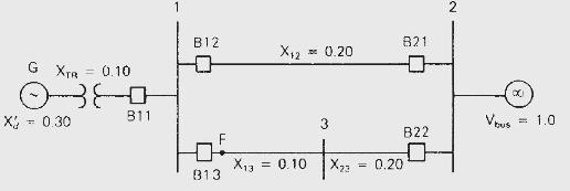
The generator in Figure 11.4 is initially operating in the steady-state condition given in Example 11.3 when a temporary three-phase-to-ground short circuit occurs at point F. Three cycles later, circuit breakers B13 and B22 permanently open to clear the fault. Use the equal-area criterion to
If breakers B13 and B22 in Problem 11.13 open later than 3 cycles after the fault commences, determine the critical clearing time.Problem 11.13The generator in Figure 11.4 is initially operating in the steady-state condition given in Example 11.3 when a temporary three-phase-to-ground short circuit
Building upon Problem 11.11, assume a \(60 \mathrm{~Hz}\) nominal system frequency, that the bus fault actually occurs on the line between buses five and two but at the bus two end, and that the fault is cleared by opening breakers B21 and B52. Again, neglecting the loads, assume that the generator
Analytically determine whether there is a critical clearing time for Problem 11.15.Problem 11.15Building upon Problem 11.11, assume a \(60 \mathrm{~Hz}\) nominal system frequency, that the bus fault actually occurs on the line between buses five and two but at the bus two end, and that the fault is
Consider the first order differential equation, \(\frac{d x_{1}}{d t}=-x_{2}\), with an initial value \(x(0)=10\). With an integration step size of 0.1 seconds, determine the value of \(x(0.5)\) using (a) Euler's method, (b) the modified Euler's method.
The following set of differential equations can be used to represent that behavior of a simple spring-mass system, with \(x_{1}(t)\) the mass's position and \(x_{2}(t)\) its velocity:\(\frac{d x_{1}}{d t}=x_{2}\)\(\frac{d x_{2}}{d t}=-x_{1}\)For the initial condition of \(x_{1}(0)=1.0,
A \(60 \mathrm{~Hz}\) generator is supplying \(400 \mathrm{MW}\) (and 0 Mvar) to an infinite bus (with 1.0 per unit voltage) through two parallel transmission lines. Each transmission line has a per unit impedance (100 MVA base) of \(0.09 j\). The per unit transient reactance for the generator is
Showing 2900 - 3000
of 5433
First
23
24
25
26
27
28
29
30
31
32
33
34
35
36
37
Last
Step by Step Answers