New Semester
Started
Get
50% OFF
Study Help!
--h --m --s
Claim Now
Question Answers
Textbooks
Find textbooks, questions and answers
Oops, something went wrong!
Change your search query and then try again
S
Books
FREE
Study Help
Expert Questions
Accounting
General Management
Mathematics
Finance
Organizational Behaviour
Law
Physics
Operating System
Management Leadership
Sociology
Programming
Marketing
Database
Computer Network
Economics
Textbooks Solutions
Accounting
Managerial Accounting
Management Leadership
Cost Accounting
Statistics
Business Law
Corporate Finance
Finance
Economics
Auditing
Tutors
Online Tutors
Find a Tutor
Hire a Tutor
Become a Tutor
AI Tutor
AI Study Planner
NEW
Sell Books
Search
Search
Sign In
Register
study help
computer science
systems analysis design
The Analysis And Design Of Linear Circuits 10th Edition Roland E. Thomas, Albert J. Rosa, Gregory J. Toussaint - Solutions
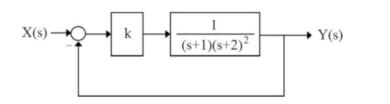
Determine the period of oscillations of the closed-loop control system's response illustrated in Fig. 3.1 .1) \(11.2 \mathrm{sec}\)2) \(6.5 \mathrm{sec}\)3) \(2.2 \mathrm{sec}\)4) \(2 \sqrt{10} \mathrm{sec}\)Figure 3.1 X(s) O k 1 (s+1)(s+2)2 Y(s)
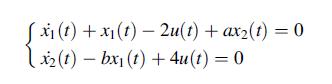
The differential equations of a control system are as follows:For what value of " \(a\) " and " \(b\) ", the system is stable?1) \(a b \geq 0\)2) \(a>0, b3) \(a>0, b=0\)4) \(a (x(t) +x(t) 2u(t) + ax2(t) = 0 x2(t)-bx1(t) + 4u(t) = 0
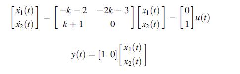
The state equations of a control system are as follows. For what value of " \(k\) ", the system is stable?1) \(k>-2\)2) \(k>-1\)3) \(-24) \((-2,-1.5) \cup(-1, \infty)\) (t) = -k-2 k+1 [10]-[17 [x2(1) -2k 3x1 (1) 0 [10] - y(t) = [1 0] [X1(0)] [x2(t)
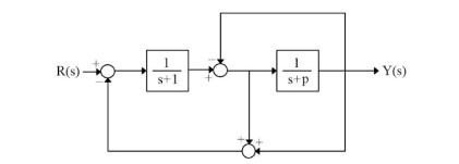
In the control system shown in Fig. 3.2 , determine the range of " \(p\) ", so that the system is stable.1) \(p>0\)2) \(p>-1\)3) \(-34) \(-3Figure 3.2 1 R(s)- Y(s). s+1 s+p
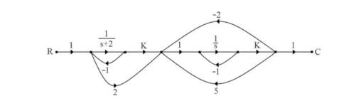
For a control system with the signal flow graph (SFG), shown in Fig. 3.3 , and the transfer function of \(\frac{C(s)}{R(s)}\), which one of the following choices is correct?1) The system is always unstable.2) For \(k3) For \(k=-1\), the system has an undamped response.4) For \(kFigure 3.3
For the control system, shown in Fig. 3.4 , determine the hidden modes of the system.1) \(1, \pm j\)2) 0 3) \(-1,0\)4) 1,0 Figure 3.4 X(s) 2+1 (s+2) Y(s)
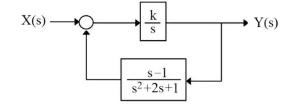
For what range of \(k\), the control system, shown in Fig. 3.5 , is stable?1) \(-\frac{4}{3}2) \(-\frac{1}{3}3) \(-\frac{5}{3}4) \(-\frac{2}{3}Figure 3.5 X(s)- k Y(s) S s-1 s2+2s+1
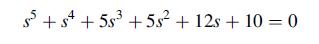
The equation below shows the characteristic equation of a control system. How many unstable poles does it have?1) 1 2) 2 3) 3 4) 0 +s+53 +5s + 12s+ 100
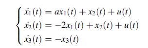
The differential equations of a control system are as follows:For what value of " \(a\) " the system is stable?1) \(a2) \(a>-2\)3) \(-24) \(1 xi(t) = axi(t) +xz(t)+u(t) x2(t) = -2x1(t) +x2(t) +u(t) x3(1)=-x3(1)
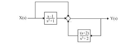
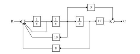
Determine the transfer function of \(\frac{C(s)}{R(s)}\) for the control system, shown in Fig. 3.6 . Is this system internally stable or unstable?1) \(\frac{3}{(s+1)(s+2)}\), stable 2) \(\frac{3}{(s+1)(s-4)}\), unstable 3) \(\frac{3}{(s+2)(s-4)}\), unstable 4) \(\frac{3}{(s+1)(s+2)}\), unstable
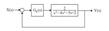
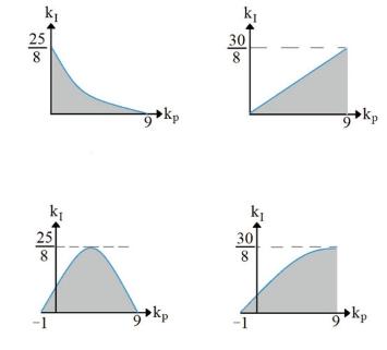
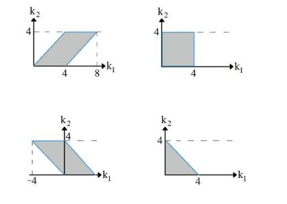
In the control system, shown in Fig. 3.7 , the controller is in the form of \(G_{c}(s)=k_{P}+\frac{k_{l}}{s}\). Which one of the choices, illustrated in Fig. 3.8 , graphically shows the stability area of the closed-loop system?Figure 3.7Figure 3.8 X(s)- Ge(s) 2 s+4s+5s+2 Y(s)
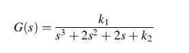
For a control system with a negative unity feedback and the following open-loop transfer function, which one of the choices, shown in Fig. 3.9 , graphically shows the stability area of both open-loop and closed-loop systems?Figure 3.9 G(s) = k s3+2s2+2s+k
Use the defining integral to find the Fourier transform of \(f(t)=A[u(t+1)-u(t-2)]\).
(a) Use the defining integral to find the Fourier transform of the following waveform:\[f(t)=A[u(t+10)-u(t-10)]\](b) Use the MATLAB function fourier to find the same transform.
Use MATLAB and the defining integral to find the Fourier transform of the following waveform:\[f(t)=5 \pi \cos (\pi t / 4)[u(t)-u(t-8)]\]
Use the inversion integral to find the inverse transform of the following function:\[F(\omega)=10 \pi[u(\omega+10)-u(\omega-10)]\]
Use MATLAB and the inversion integral to find the inverse transform of the following function:\[F(\omega)=\cos (\pi \omega / 4)[u(\omega+4)-u(\omega-4)]\]
First find the transforms of the following functions. Then determine what type of characteristics they possess.(a) \(f_{1}(t)=100 e^{-100 t} u(t)\)(b) \(f_{2}(t)=1.25\left[e^{-100 t}-e^{-500 t}ight] u(t)\)(c) \(f_{3}(t)=\frac{500}{9}\left[10 e^{-100 t}-e^{-10 t}ight] u(t)\)
Find the inverse transforms of the following functions:(a) \(F_{1}(\omega)=\frac{10,000}{j \omega(j \omega+100)(j \omega+1000)}\)(b) \(F_{2}(\omega)=\frac{-10 \omega^{2}}{j \omega(j \omega+20)(j \omega+40)}\)
Use MATLAB's fourier function to find the Fourier transforms of the following waveforms:(a) \(f_{1}(t)=3 u(-t)-3\)(b) \(f_{2}(t)=-\operatorname{sgn}(t)-u(-t)\)(c) \(f_{3}(t)=\operatorname{sgn}(t)+1\)
Find the Fourier transforms of the following waveforms:(a) \(f_{1}(t)=\frac{10}{j}\left(e^{i 2 t}-e^{-j 2 t}ight)+10\left(e^{j i t}+e^{-j 2 t}ight)\)(b) \(f_{2}(t)=\frac{10}{t}(\sin 5 t)\)
Find the Fourier transforms of the following waveforms:(a) \(f_{1}(t)=100 \sin [2 \pi(t-10)]\)(b) \(f_{2}(t)=5 e^{j 10 t} \operatorname{sgn}(t)\)
Find the inverse transforms of the following functions:(a) \(F_{1}(\omega)=6 \pi \delta(\omega)+6 \pi \delta(\omega-3)+6 \pi \delta(\omega-4)\)(b) \(F_{2}(\omega)=4 \pi \delta(\omega)-j 6 / \omega+4 \pi \delta(\omega-2)\)(c) \(F_{3}(\omega)=10 \pi \delta(\omega)-j 20 / \omega\)
Use the duality property to find the inverse transforms of the following functions:(a) \(F_{1}(\omega)=50 \cos (100 \omega)\)(b) \(F_{2}(\omega)=10 u(\omega)-5\)(c) \(F_{3}(\omega)=6 e^{-|2 \omega|}\)
Use the time-shifting property to find the inverse transforms of the following functions:(a) \(F_{1}(\omega)=[6 \pi \delta(\omega) j 6 / \omega] e^{-j 5 \omega}\)(b) \(F_{2}(\omega)=50 e^{-j 4 \omega} /(j \omega+5)\)(c) \(F_{3}(\omega)=2 \cos (20 \omega) / j \omega\)
Given that the Fourier transform of \(f(t)\) is\[F(\omega)=\frac{100,000}{(j \omega+500)(j \omega+1000)}\]Use the integration property to find the waveform\[g(t)=\int_{-\infty}^{t} f(x) d x\]
Use the reversal property to show that\[\mathscr{F}\left\{A e^{-\alpha t \mid} \operatorname{sgn}(t)ight\}=\frac{-2 A j \omega}{\omega^{2}+\alpha^{2}}\]
Use the frequency shifting property to show that\[\mathscr{F}\{\cos (\beta t) u(t)\}=\frac{j \omega}{\beta^{2}-\omega^{2}}+\frac{\pi}{2}[\delta(\omega-\beta)+\delta(\omega+\beta)]\]
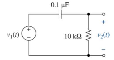
The input in Figure P18-17 is \(v_{1}(t)=5 e^{-|t|} \mathrm{V}\). Use Fourier transforms to find \(v_{2}(t)\). V(t) + 0.1 uF + 10 V(1)
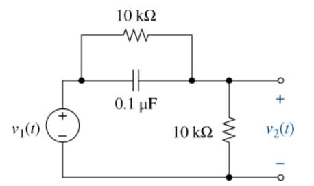
The input in Figure P18-18 is \(v_{1}(t)=1 \operatorname{Osgn}(t)\) V. Use Fourier transforms to find \(v_{2}(t)\). V(t) +1 10 www 0.1 F 10 V2(t)
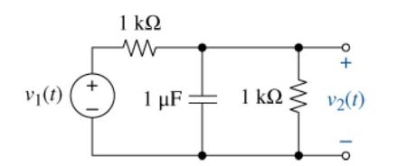
The input in Figure P18-19 is \(v_{1}(t)=10 e^{10 t} u(-t)\) V. Use Fourier transforms to find \(v_{2}(t)\). 1 w + V(t) + 1 F 1 V2(1)
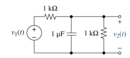
The input in Figure P18-19 is \(v_{1}(t)=2 \operatorname{sgn}(t) \mathrm{V}\). Use Fourier transforms to find \(v_{2}(t)\). V(t) 1 ww + 1 + 1 F: 1 v2(1) 19
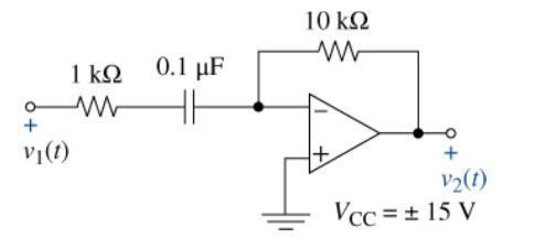
(a) The input in Figure P18-21 is \(v_{1}(t)=3 u(-t) \mathrm{V}\). Use Fourier transforms to find \(v_{2}(t)\).(b) Will the OP AMP saturate? 1 0.1 F ww + V(t) 10 w + V2(t) Vcc = 15 V
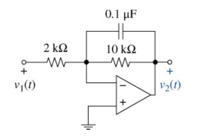
The input in Figure P18-22 is \(v_{1}(t)=3 e^{-2|t|} u(-t) \mathrm{V}\). Use Fourier transforms to find \(v_{2}(t)\). 0.1 F 2 10 w ww + + V(1) + V(1)
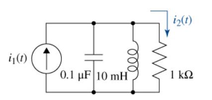
The input in Figure P18-23 is \(i_{1}(t)=10 e^{-5|t|} \mathrm{mA}\). Use Fourier transforms to find \(i_{2}(t)\). i2(t) i(t) 0.1 uF 10 mH 1
The impulse response of a linear system is \(h(t)=5 e^{-3 t}\) \(u(t)\). Find the output for an input \(x(t)=u(-t)\).
The impulse response of a linear system is \(h(t)=e\) \(-2|t|\). Find the output for an input \(x(t)=u(-t)\).
The impulse response of a linear system is \(h(t)=\delta(t\) )\(-5 e^{-2 t} u(t)\). Use MATLAB and Fourier transform techniques to find the output for an input \(x(t)=\operatorname{sgn}(-t)\).
The impulse response of a linear system is \(h(t)\) \(=A\left[\delta(t)-\alpha e^{-\alpha t} u(t)ight]\), with \(\alpha>0\). Let \(A=10\) and \(\alpha=3\) and use MATLAB to plot \(|H(\omega)|\). On the same axes, plot \(|H(\omega)|\) for \(A=10\) and \(\alpha=6\). Describe the system frequency
The impulse response of a linear system is \(h(t)=A\) \([\delta(t)-\sin (\beta t) / \pi t]\). Let \(A=5\) and \(\beta=2\) and use MATLAB to plot \(|H(\omega)|\). On the same axes, plot \(|H(\omega)|\) for \(A=5\) and \(\beta=4\). Describe the system frequency response and the influence of the
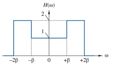
Use MATLAB's ifourier function to find the system impulse response \(h(t)\) if the frequency response of a linear system is shown in Figure P18-29. 2 H(0) 1 -2 - 0 + +2 3
Find the \(1-\Omega\) energy carried by the signal \(F(\omega)=25 /\left(\omega^{2}ight.\) \(+625)\).
Compute the \(1-\Omega\) energy carried by the signal \(f(t)=\) \(9 e^{4.5^{t}} u(-t)\).
Find the \(1-\Omega\) energy carried by the signal\[F(\omega)=\frac{j \omega A}{\omega^{2}+\alpha^{2}}\]Then, find the percentage of the \(1-\Omega\) energy carried in the frequency band \(|\omega| \leq \alpha\).
The impulse response of a filter is \(h(t)=3 e^{-200}\) \({ }^{t} u(t)\). Find the \(1-\Omega\) energy in the output signal when the input is \(x(t)=4 e^{-20 t} u(t)\). Verify your result using MATLAB.
The impulse response of a filter is \(h(t)=50 e^{-20 t} u(t)\). Find the \(1-\Omega\) energy in the output signal when the input is \(x(t)\) \(=u(t)\).
The current in a \(50-\mathrm{k} \Omega\) resistor is \(i(t)=-5 u(t+1)\) \(+10 u(t)-5 u(t-1) \mathrm{A}\). Find the total energy delivered to the resistor.
The transfer function of an ideal bandpass filter is \((\omega)\) \(=1\) for \(1800 \leq \omega \leq 2200 \mathrm{rad} / \mathrm{s}\). Use MATLAB to find the \(1-\Omega\) energy carried by the output signal when the input is \(x(t)=10\) \(e^{-2000 t} u(t)\). What percentage of the input signal
Given a rectangular pulse as shown in Figure 13-4, with amplitude A, width \(T\), and period \(T_{0}\), we can compute and plot the coefficients in the corresponding Fourier series. If we allow \(T_{\mathrm{o}}\) to increase to infinity, the waveform is a single pulse and the Fourier series
Theoretically, an impulse has an amplitude spectrum that is constant at all frequencies. In practice, a constant spectrum across an infinite bandwidth cannot be achieved, nor is it really necessary. What is required is an amplitude spectrum that is "essentially" constant over the frequency range of
The SDLC is just one model for systems development. Find at least one more and describe the differences.
Draw DFDs for each of these scenarios:(a) A customer goes into a bookshop and asks for this book. The member of staff looks for the book in the online stock catalogue and reports that the book is sold out.(b) Every month, the Medical Centre receives a list of current drugs available from the drug
Draw a physical DFD to model this vet practice scenario. Hallam Vets consists of two vets plus a receptionist. Both vets maintain records of treatment sessions. In addition, they maintain detailed animal records held in reception. When an owner arrives with an animal, the receptionist enters new
Draw an entity model to model the following car rental business scenario:● Cars are always rented from one location and are brought back to the same location.● Customers may pay by cash or credit card.● Customers who call the agency may request a particular car make, model etc. if
Draw an entity model to model this university scenario:● A university department employs lecturers and clerical staff.● It offers a three-year degree.● A student has to take 12 modules during the course.● Each lecturer teaches one or more courses.● Courses may be taught by more than one
Logicalize the following, if necessary:● Type and copy invoice● Collate customer details● SR1 form – blue● File details from new customer● View patient’s name and address● Photocopy application form● Delivery note
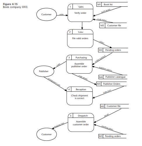
Logicalize the mail order book company DFD shown in Figure 4.15 (overleaf). Figure 4.15 Book company DFD. Customer order Sales Verify order M1 Book list Sales File valid orders M2 Customer file Purchasing Assemble publisher order M3 Pending orders Publisher consignment noe Reception Check shipment
Produce a decision table to model the logic in this scenario: A postal delivery company delivers parcels air or rail transport. The price of delivery by air depends upon the weight of the parcel. There is a basic charge of £5 per kg up to 50 kg. Excess weight over 50 kg is charged at £3 per kilo.
Produce a structured English specification for this scenario: A travel agent has account customers and individual customers. Account customers who have spent over £25,000 in the past year get a discount of 25%. Otherwise, they get a 10% discount. Individual customers who have booked holidays
Design a report for the Medical Centre showing the appointments for the following week. The report will be used by the receptionists to check patients as they arrive for their appointment, so consider what information will be required on the report.
Normalize the following data taken from a student assessment form, bearing in mind that students will take a number of modules:- Student Number- Student Name- Student Address- Module Code- Module Name- Module Mark- Module Grade
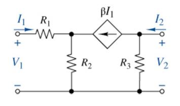
Find the \(y\)-parameters of the two-port network in Figure P17-4. V 16 R BI R R3 ww 18+ V2 19
Find the load impedance \(Z\) for the following complex powers.(a) When \(S=2000+j 2500 \mathrm{VA}\) and \(|\mathbf{V}|=1000 \mathrm{~V}\).(b) When \(|S|=15 \mathrm{kVA}, P=12 \mathrm{~kW}, Q>0\), and \(|\mathbf{I}|=50 \mathrm{~A}\).
An inductive load draws an apparent power of \(50 \mathrm{kVA}\) at a power factor of 0.7 from a \(3600-V(\mathrm{rms})\) source. Find the complex power \(S\) and the load impedance \(Z\).
Design an appropriate load that will draw 15 \(\mathrm{A}(\mathrm{rms}), 6 \mathrm{~kW}\), and \(4.5 \mathrm{kVAR}\) from a \(60-\mathrm{Hz}\) source. Would the components be larger or smaller if the source was \(50 \mathrm{~Hz}\) ? What is the power factor of your load?
Design an appropriate load that will draw \(28 \mathrm{~A}\) (rms), \(2.2 \mathrm{~kW}\), at \(110 \mathrm{~V}\) (rms) from a \(400-\mathrm{Hz}\) source. Wha1 is its power factor? Prove your design using Multisim.
A load made up of a \(220-\Omega\) resistor in parallel with a \(200-\mathrm{mH}\) inductor is connected across a \(240-\mathrm{V}(\mathrm{rms}), 50-\mathrm{Hz}\) voltage source. Find the complex power delivered to the load and the load power factor. State whether the power factor is lagging or
An arc welder presents a load made up of a 100- \(\Omega\) resistor in parallel with a \(12-\mu \mathrm{F}\) capacitor in a \(60-\mathrm{Hz}, 110-\mathrm{V}\) (rms) supply.(a) Find the complex power delivered to the load and the load power factor. State whether the power factor is lagging or
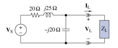
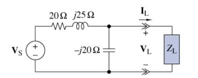
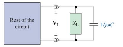
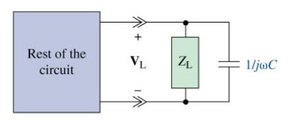
In Figure P16-11, the load \(Z_{\mathrm{L}}\) is a \(60-\Omega\) resistor in series with a capacitor whose reactance is \(-30 \Omega\). The source voltage is \(440 \mathrm{~V}\) (rms). Find the complex power produced by the source and the complex power delivered to the load. Vs 1 + 200 j250 -j20 IL
Repeat Problem 16-11 when \(Z_{\mathrm{L}}\) is a \(30-\Omega\) resistor in parallel with an impedance of \(30-j 30 \Omega\).Data From Problem 16-11In Figure P16-11, the load \(Z_{\mathrm{L}}\) is a \(60-\Omega\) resistor in series with a capacitor whose reactance is \(-30 \Omega\). The source
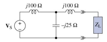
In Figure P16-13, the load \(Z_{\mathrm{L}}\) is a 1500- \(\Omega\) resistor and the source voltage is \(440 \mathrm{~V}\) (rms). Find the complex power produced by the source. Vs j100 j100 --j25 92
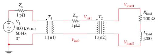
The circuit in Figure P16-14 shows a power line distribution and an intermediate substation and a final user substation. The source \(\mathbf{V}_{S}\) generates and steps up the voltage to \(400 \mathrm{kV}\) (rms), 60-Hz power. This power line is routed to an intermediate substation which steps
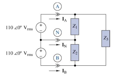
In Figure P16-15, the three load impedances are \(Z\) \({ }_{1}=20+j 15 \Omega, Z_{2}=25-j 10 \Omega\), and \(Z_{3}=75+j 50 \Omega\). UseMATLAB to solve for the three currents \(\mathbf{I}_{\mathrm{A}}, \mathbf{I}_{\mathrm{B}}\), and \(\mathbf{I}_{\mathrm{N}}\), then the total complex power
Two loads are connected in parallel across an \(880 \mathrm{~V}(\mathrm{rms})\) line. The first load draws an average power of \(20 \mathrm{~kW}\) at a lagging power factor of 0.87 . The second load draws \(15 \mathrm{~kW}\) at a lagging power factor of 0.67 . Find the overall power factor of the
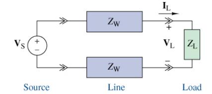
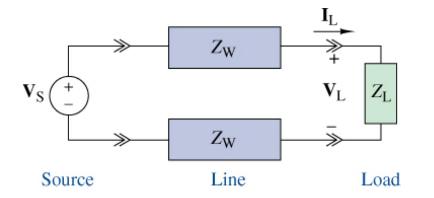
The average power delivered to the load \(Z_{\mathrm{L}}\) in Figure P16-17 is \(46 \mathrm{~kW}\) at a lagging power factor of 0.7. The load voltage is \(2.4 \mathrm{kV}(\mathrm{rms})\) and the line has an impedance of \(Z_{\mathrm{W}}=1\) \(+j \Omega /\) wire. Find the apparent power produced by
Repeat Problem 16-17 if the load power factor is a leading 0.92 .Data From Problem 16-17The average power delivered to the load \(Z_{\mathrm{L}}\) in Figure P16-17 is \(46 \mathrm{~kW}\) at a lagging power factor of 0.7. The load voltage is \(2.4 \mathrm{kV}(\mathrm{rms})\) and the line has an
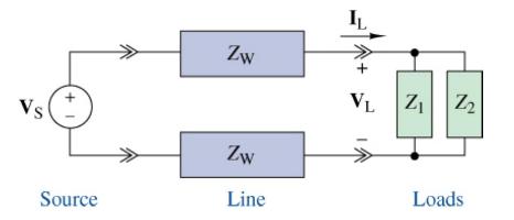
In Figure P16-20, the voltage across the two loads is \(\mid V_{\mathrm{L}}\) I \(=4.8 \mathrm{kV}\) (rms). The load \(Z_{1}\) draws an average power of \(15 \mathrm{~kW}\) at a lagging power factor of 0.8 . The load \(Z_{2}\) draws an apparent power of \(12 \mathrm{kVA}\) at a lagging power factor
The two loads in Figure P16-20 draw apparent powers of \(\left|S_{1}ight|=50 \mathrm{kVA}\) at a lagging power factor of 0.72 and | \(S_{2} \mid=25 \mathrm{kVA}\) at unity power factor. The voltage across the loads is \(3.8 \mathrm{kV}\) and the line has an impedance of \(Z_{\mathrm{W}}=5+j 26
In Figure P16-22, the load voltage is \(\left|V_{L}ight|=4160 \mathrm{~V}\) (rms) at \(60 \mathrm{~Hz}\) and the load \(Z_{\mathrm{L}}\) draws an average power of 12 \(\mathrm{kW}\) at a lagging power factor of 0.75 . Find the overall power factor of the combination if the parallel capacitance is
In Figure P16-22, the load voltage is \(\left|V_{\mathrm{L}}ight|=\) \(2400 \mathrm{~V}\) (rms) at 60 Hz. The load \(Z_{\mathrm{L}}\) draws an apparent power of \(25 \mathrm{kVA}\) at a lagging power factor of 07 . Select the value of the capacitance required to raise the overall power factor of
A load draws \(4 \mathrm{~A}\) (rms) and \(5 \mathrm{~kW}\) at a power factor 0.8 (lagging) from a 60-Hz source. Select an appropriate capacitor to be placed in parallel with the load to raise the overall power factor to 0.95 .
A 60-Hz, 200-hp, 240-V (rms) motor draws 160 \(\mathrm{kW}\) of power with a 0.72 lagging power factor. Compute the complex power drawn by the motor. Then select an appropriate capacitor to improve the power factor to 0.98 and then recalculate the new complex power drawn.
In a balanced three-phase circuit the line voltage magnitude is \(V_{\mathrm{L}}=9.8 \mathrm{kV}\) (rms). For a positive phase sequence:(a) Find all of the line and phase voltage phasors using \(\mathrm{V}\) \(\mathrm{AB}\) as the phase reference.(b) Sketch a phasor diagram of the line and phase
In a balanced three-phase circuit \(\mathbf{V}_{\text {an }}=500
A balanced Y-connected three-phase source has \(V_{\mathrm{AN}}=\) \(240
In a balanced three-phase circuit \(V_{\mathrm{CN}}=2400
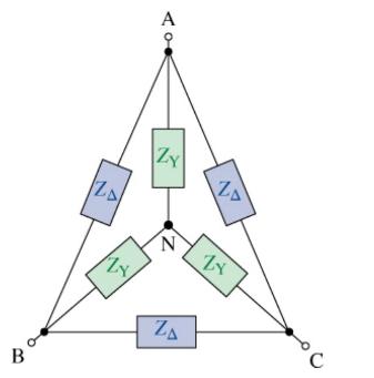
A three-phase load is configured as shown in Figure P16\(3 \underline{0}\) with \(Z_{\mathrm{Y}}=10-j 5 \Omega\) and \(Z_{\Delta}=60-j 15 \Omega\).(a) Find the equivalent \(Z_{\mathrm{Y}}\) load.(b) The combined load is connected to a balanced Y-connected three-phase source with
A balanced Y-connected load with \(Z_{Y}=100-j 20\) \(\Omega\) per phase is connected in parallel with a balanced \(\Delta\) connected load with \(Z_{\Delta}=120+j 500 \Omega\) per phase.(a) Find the phase impedance of an equivalent \(Y\) connected load and an equivalent \(\Delta\)-connected load.
An old balanced \(\Delta\) - \(\Delta\) circuit needs to be upgraded to a \(\mathrm{Y}-\mathrm{Y}\) system. The current \(\Delta\)-connected source produces \(\mathbf{V}_{\mathrm{AB}}=\) \(2400
In a balanced \(Y-Y\) circuit, the line voltage and phase impedance are \(V_{\mathrm{L}}=480 \mathrm{~V}(\mathrm{rms})\) and \(Z_{\mathrm{Y}}=20+j 10 \Omega /\) phase. Using \(
In a balanced Y-Y circuit, the line voltage is \(V_{\mathrm{L}}=440 \mathrm{~V}\) (rms). The phase impedance is \(Z_{\mathrm{Y}}=30+j 40 \Omega /\) phase. Using \(
A physical plant is served by a balanced \(\mathrm{Y}-\Delta\) circuit. The line voltage and phase impedance are \(V_{\mathrm{L}}=440 \mathrm{~V}(\mathrm{rms})\) and \(Z_{\Delta}=16+j 12 \Omega /\) phase. The owner wants to add a new \(Z_{\mathrm{Y}}=15-\) \(j 20 \Omega /\) phase load in parallel
In a balanced \(\Delta-Y\) circuit, the line voltage and phase impedance are \(V_{\mathrm{L}}=4.16 \mathrm{kV}(\mathrm{rms})\) and \(Z_{\mathrm{Y}}=250
In a balanced Y-connected load, the line current and phase impedance are \(I_{\mathrm{L}}=4.7 \mathrm{~A}(\mathrm{rms})\) and \(Z_{\mathrm{Y}}=20+j 16\) \(\Omega /\) phase. Using \(
An average power of \(5 \mathrm{~kW}\) is delivered to a balanced three-phase load with a phase impedance of \(Z_{\mathrm{Y}}=40+j 30\) \(\Omega /\) phase. Find \(V_{\mathrm{L}}\) and the complex power delivered to the load.
There is a need to design an appropriate load to connect a three-phase source. The source provides \(24 \mathrm{z} 33.7^{\circ}\) \(\mathrm{kVA}\) at \(60 \mathrm{~Hz}\) of complex power to a balanced \(Z_{\mathrm{Y}}\) load. Your load needs a line voltage of \(3.5 \mathrm{kV}\) (rms) to operate
A balanced three-phase load has a phase impedance of \(Z\) \(\mathrm{Y}=30+j 40 \Omega /\) phase. The line voltage at the load is \(V_{\mathrm{L}}=440 \mathrm{~V}\) (rms). Find \(I_{\mathrm{L}}\) and the complex power delivered to the load.
Showing 2600 - 2700
of 5433
First
20
21
22
23
24
25
26
27
28
29
30
31
32
33
34
Last
Step by Step Answers