New Semester
Started
Get
50% OFF
Study Help!
--h --m --s
Claim Now
Question Answers
Textbooks
Find textbooks, questions and answers
Oops, something went wrong!
Change your search query and then try again
S
Books
FREE
Study Help
Expert Questions
Accounting
General Management
Mathematics
Finance
Organizational Behaviour
Law
Physics
Operating System
Management Leadership
Sociology
Programming
Marketing
Database
Computer Network
Economics
Textbooks Solutions
Accounting
Managerial Accounting
Management Leadership
Cost Accounting
Statistics
Business Law
Corporate Finance
Finance
Economics
Auditing
Tutors
Online Tutors
Find a Tutor
Hire a Tutor
Become a Tutor
AI Tutor
AI Study Planner
NEW
Sell Books
Search
Search
Sign In
Register
study help
computer science
systems analysis design
Power System Analysis And Design 6th Edition J. Duncan Glover, Thomas Overbye, Mulukutla S. Sarma - Solutions
In a no-load and lossless transmission line, which one of the following relations is correct? Herein, \(\mathbf{V}_{\mathbf{R}}, \mathbf{V}_{\mathbf{S}}, \beta, \gamma\), and \(l\) are the voltage of receiving end, voltage of sending end, phase constant, propagation constant, and length of line,
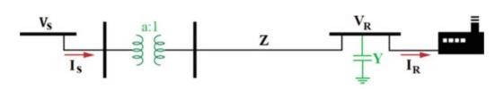
A factory is supplied by an ideal transformer through a short transmission line. At the bus of the factory, a shunt capacitor has been installed to correct its power factor. Which one of the transmission matrices below is correct for this power system?1) \(\left[\begin{array}{ll}\frac{1}{a} & 0
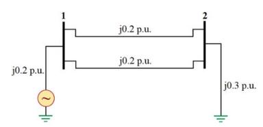
For the power system illustrated in Fig. 7.1, determine \(Z_{22}\) of the network impedance matrix ([ \(\left.Z_{\text {Bus }}ight]\) ).1) \(j 0.6 \Omega\)2) \(j 0.06 \Omega\)3) \(j 0.4 \Omega\)4) \(j 0.15 \Omega\) j0.2 p.u. j0.2 p.u. j0.2 p.u. j0.3 p.u.
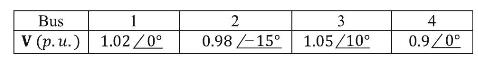
The network impedance matrix ( \(\left[\mathrm{Z}_{\mathrm{Bus}}ight]\) ) and the result of load flow simulation problem are presented in the following. If a capacitor with the reactance of \(3.4 p . u\). is connected to the fourth bus, determine its updated voltage:\[\left[\mathrm{Z}_{\text {Bus
In a three-bus power system, the voltage of the second bus is about \(\left(1.2 \angle 0^{\circ}ight) p . u\), and the network impedance matrix is as follows. If an inductor with the reactance of \(2.7 p . u\). is connected to the second bus, determine the voltage variation of the third
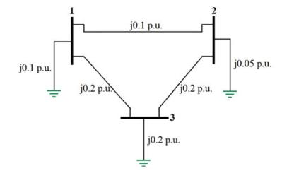
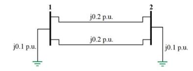
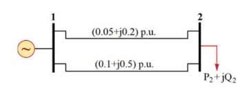
For the power system shown in Fig. 7.2, determine the network admittance matrix ([ \(\left.\mathrm{Y}_{\text {Bus }}ight]\) ).1) \(j\left[\begin{array}{ccc}-20 & 15 & 15 \\ 15 & -25 & 10 \\ 15 & 10 & -30\end{array}ight]\) p.u.2) \(j\left[\begin{array}{ccc}-25 & 10 &
For the power system shown in Fig. 7.3, determine the network impedance matrix \(\left(\left[Z_{\text {Bus }}ight]ight.\) ).1) \(j\left[\begin{array}{cc}\frac{2}{30} & \frac{1}{30} \\ \frac{1}{30} & \frac{2}{30}\end{array}ight]\) p.u.2) \(j\left[\begin{array}{cc}\frac{1}{15} &
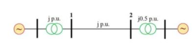
For the power system shown in Fig. 7.4, determine the detriment of the network impedance matrix ([Z \(\left.\mathrm{Z}_{\text {Bus }}ight]\) ).1) -0.5 2) 0.5 3) -0.2 4) 0.2 jp.u. j0.5 p.u. 0101 toto jp.u.
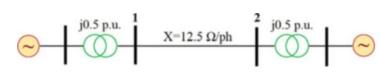
For the power system shown in Fig. 7.5, determine the value of \(\frac{Z_{12}}{Z_{22}}\), belonging to \(\left[Z_{\text {Bus }}ight]\), if the base voltage in the transmission line and the base MVA are \(50 \mathrm{kV}\) and 100 MVA, respectively.1) 0.5 2) 0.75 3) 1 4) 2 jo.5 p.u X-12.5 2ph jo.5
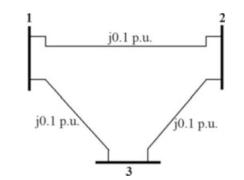
In a three-bus power system shown in Fig. 7.6, determine the sum of the diagonal components of the network admittance matrix ( \(\left[\mathrm{Y}_{\text {Bus }}ight]\) ).1) \(-j 60\) p. и.2) \(-j 20 p . u\).3) \(-j 30 p . u\).4) \(-j 10 p . u\). j0.1 p.u. j0.1 p.u. 3 10.1 p.u.
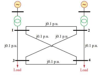
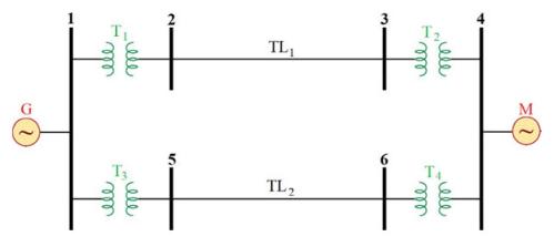
The impedance diagram of a three-phase four-bus power system is shown in Fig. 7.7.If the lines of 2-4 and 1-3 are removed from the system, the network admittance matrix can be presented in the form of [Y \(\mathrm{Y}_{\text {Bus, }}\), \(\left.N_{\text {New }}ight]=\left[\mathrm{Y}_{\text {Bus
The network admittance matrix of a four-bus power system is presented in the following. Determine the updated network admittance matrix if the second and the third buses are short-circuited:\[\left[\mathrm{Y}_{\text {Bus }}ight]=j\left[\begin{array}{cccc}-5 & 4 & 3 & 2 \\4 & -10 & 2 & 1 \\3 & 2 &
The network admittance matrix of a power system is presented in the following. There are two parallel similar lines between the buses. If one of them is disconnected from bus 1 and then grounded, determine the updated network admittance
In a load flow problem, which type of the bus has a known active power?1) Load bus 2) Voltage-controlled bus 3) All buses except slack bus 4) None of them.
To speed up the algorithm of Gauss-Seidel load flow, an accelerating factor \((\alpha)\) is usually used. Which one of the following relations presents that?1) \(\mathbf{V}_{\mathbf{i}, \mathbf{A c c}}^{(\mathbf{k}+\mathbf{1})}=\mathbf{V}_{\mathbf{i}}^{(\mathbf{k})}+\alpha \Delta
Which one of the following choices is correct about the DC load flow (DCLF), Decoupled Load flow (DLF), and Newton-Raphson load flow (NRLF)?1) DLF is faster than DCLF, and DCLF is faster than NRLF.2) DCLF is not appropriate for the AC power systems, and DCLF has more convergence probability
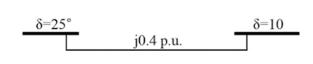
Use DC load flow to determine the active power flowing through the line. Herein, \(S_{B}=100\) MVA.1) \(32.2 \mathrm{MW}\)2) \(85.6 \mathrm{MW}\)3) \(41.7 \mathrm{MW}\)4) \(65.4 \mathrm{MW}\) 8-25 j0.4 p.u. 8-10
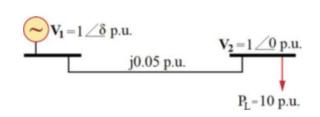
In the power system, shown in Fig. 9.2, determine \(\delta\). Do not use DC load flow approximation.1) \(60^{\circ}\)2) \(30^{\circ}\)3) \(90^{\circ}\)4) \(0^{\circ}\) V-1/8 p.u. j0.05 p.u. V-1/0 p.u. P-10 p.u.
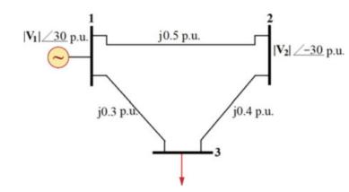
Calculate \(P_{12}\) by using DC load flow. Herein, assume \(\pi \equiv 3\).2) \(2 p . u\).3) \(3 p . u\).4) \(3.5 \mathrm{p} . u\). Vil 30 p.u. j0.3 p.u j0.5 p.u. jo.4 p.u. Val-30 p.u.
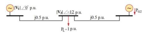
Use DC load flow to determine \(P_{G 2}\). Herein, assume \(\pi \equiv 3\).1) 0.2 p.u.2) \(0.25 p . u\).3) \(0.6 \mathrm{p} . u\).4) \(0.75 p \cdot u\). Vil 20 p.u. j0.5 p.u. IVlZ-12 p.u. P-1 p.u. j0.5 p.u. || Par
Determine the inverse matrix of Jacobian matrix considering the following terms:\[\left\{\begin{array}{l}P_{2}=\delta_{2}+3\left|\mathbf{V}_{2}ight| \\Q_{2}=0.1 \delta_{2}+\frac{1}{5}\left|\mathbf{V}_{1}ight|+\left|\mathbf{V}_{2}ight|\end{array}ight.\]1) \(\left[\begin{array}{cc}3 & 1 \\ 1
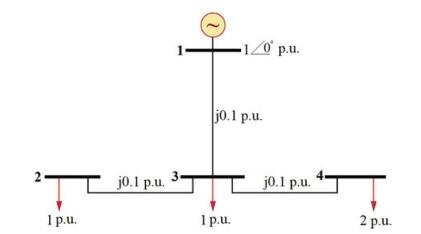
Use DC load flow to determine the phase angle of bus 4. Herein, assume \(\pi \equiv 3\).1) \(-45^{\circ}\)2) \(-36^{\circ}\)3) \(-30^{\circ}\)4) \(-15^{\circ}\) 2 1 p.u. jo.1 p.u. 3 -1/0 p.u. jo.1 p.u. 1p.u. j0.1 p.u. 2 p.u.
In a power plant, the power loss coefficients for the two power generation units are \(L_{1}=\$ 1.5 / M W, L_{2}=\$ 1.8 / M W\). Calculate the total generation of the units if Lagrange Multiplier \((\lambda)\) is about \(\$ 300 / M W h\), and the generation cost functions of the units are as
In a power plant, the generation cost functions of the units are as follows:\[\left\{\begin{array}{l}C_{1}=0.0075 P_{G 1}^{2}+50 P_{G 1}+1000 \\C_{2}=0.005 P_{G 2}^{2}+45 P_{G 2}+3000\end{array}ight.\]Solve the economic load dispatch problem for the load demand of 1000 MW.1) \(P_{G 1}=900
In a power plant, the generation cost functions of the units are as follows:\[\left\{\begin{array}{c}C_{1}=0.05 P_{G 1}^{2}+50 P_{G 1}+1500 \\C_{2}=0.075 P_{G 2}^{2}+40 P_{G 2}+2000\end{array}ight.\]Solve the economic load dispatch problem for the total load of 1400 MW.1) \(P_{G 1}=400 \mathrm{MW},
In a power plant, the generation cost functions of the units are as follows:\[\left\{\begin{array}{l}C_{1}=135 P_{G 1}^{2}+100000 P_{G 1} \\C_{2}=115 P_{G 2}^{2}+85000 P_{G 2}\end{array}ight.\]Solve the economic load dispatch problem for the total load of 1000 MW.1)
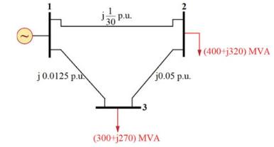
The single-line diagram of a power system is shown in Fig. 9.7.The voltage of bus 1 is about \(\left(1 \angle 0^{\circ}ight) p . u\). and \(S_{B}=100\) MVA. Calculate \(\mathbf{V}_{\mathbf{2}}\) using Gauss-Seidel load flow after one iteration if \(\mathbf{V}_{2}^{(\mathbf{0})}=\left(1 \angle
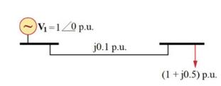
Use Newton-Raphson load flow (NRLF) to determine the voltage of load bus after one iteration.1) \(0.952) \(0.983) \(0.934) \(0.9 V=1/0 p.u. jo.1 p.u. (1 + j0.5) p.u.
What is the phasor representation of the voltage signal of \(\sqrt{2} \cos (t)\) ?1) \(1 \mathrm{~V}\)2) \(\left(1 \angle 90^{\circ}ight) \mathrm{V}\)3) \(0 \mathrm{~V}\)4) \(\left(1 \angle-90^{\circ}ight) \mathrm{V}\)
Represent the current signal of \(\sqrt{2} \sin (t)\) in phasor domain.1) \(1 \mathrm{~A}\)2) \(\left(1 \angle 90^{\circ}ight) \mathrm{V}\)3) \(0 \mathrm{~A}\)4) \(\left(1 /-90^{\circ}ight) \mathrm{V}\)
Define the signal of \(\cos \left(2 t+30^{\circ}ight)\) in phasor domain.1) \(1 \angle 30^{\circ}\)2) \(2 \angle-30^{\circ}\)3) \(\frac{1}{\sqrt{2}} \angle 0^{\circ}\)4) \(\frac{1}{\sqrt{2}} \angle 30^{\circ}\)
Represent the signal of \(10 \sin \left(t-60^{\circ}ight)\) in phasor form.1) \(10 /-150^{\circ}\)2) \(10 /-60^{\circ}\)3) \(5 \sqrt{2} /-150^{\circ}\)4) \(10 / 60^{\circ}\)
In the single-phase power system of Fig. 1.1, the voltage and current are as follows:\[\begin{aligned}v(t) & =110 \cos \left(\omega t+30^{\circ}ight) V \\i(t) & =0.5 \cos \left(\omega t-30^{\circ}ight) A\end{aligned}\]Determine the impedance, resistance, and reactance of the system seen
In the single-phase power system of Fig. 1.1, the voltage and current are given as follows:\[\begin{gathered}v(t)=100 \sqrt{2} \cos (t) V \\i(t)=\sqrt{2} \cos \left(t-30^{\circ}ight) A\end{gathered}\]Determine the admittance, conductance, and susceptance of the system seen from the beginning of the
The impedance of a generator, with the rated specifications of \(20 \mathrm{kV}\) and 200 MVA, is \(\mathbf{Z}=j 0.2 p\). \(u\). Determine its reactance in percent if \(21 \mathrm{kV}\) and \(100 \mathrm{MVA}\) are chosen as the base voltage and power.1) \(11 \%\)2) \(10.5 \%\)3) \(11.7 \%\)4)
The reactance of a generator, with the nominal specifications of \(14 \mathrm{kV}\) and \(500 \mathrm{MVA}\), is \(1.1 p . u\). Determine its impedance in percent if \(20 \mathrm{kV}\) and \(100 \mathrm{MVA}\) are chosen as the base voltage and power.1) \(30.8 \%\)2) \(10.78 \%\)3) \(60.8 \%\)4)
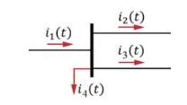
In the power bus of Fig. 1.2, determine the \(i_{3}(t)\) if we know that \(i_{1}(t)=10 \cos (10 t) A, i_{2}(t)=10 \sin (10 t) A\), and \(i_{4}(t)=10 \sqrt{2} \cos \left(10 t+45^{\circ}ight) A\).1) \(10 \sqrt{2} \mathrm{~A}\)2) \(\left(5 /-45^{\circ}ight) A\)3) \(\left(10 / 45^{\circ}ight) A\)4) \(0
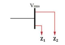
In the single-phase power bus of Fig. 1.3, \(V_{r m s}=200 \mathrm{~V}\) and the equivalent impedance of the loads are \(\mathbf{Z}_{\mathbf{1}}=(8-j 6) \Omega\) and \(\mathbf{Z}_{2}=(3+j 4) \Omega\). Calculate the total active power consumed in the bus.1) \(8 \mathrm{~kW}\)2) \(15 \mathrm{~kW}\)3)
Calculate the instantaneous power of a single-phase power system that its voltage and current are \(v(t)=\) \(110 \sqrt{2} \cos (120 \pi t) V\) and \(i(t)=2 \sqrt{2} \cos \left(120 \pi t-60^{\circ}ight) A\).1) \(110 \mathrm{~W}\)2) \(220 \cos \left(240 \pi t-60^{\circ}ight) \mathrm{W}\)3) \(55+110
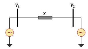
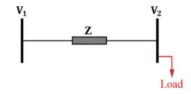
In the single-phase power system of Fig. 1.4, calculate the active and reactive powers transferred from bus 1 to bus 2. Consider the following data:\[\mathbf{V}_{\mathbf{1}}=\left(10 \angle 30^{\circ}ight) V, \mathbf{V}_{\mathbf{2}}=\left(5 \sqrt{3} \angle 0^{\circ}ight) V, \mathbf{Z}=j 5
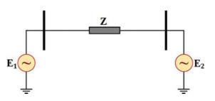
In the power system of Fig. 1.5, \(\mathbf{E}_{\mathbf{1}}=200 \angle-30^{\circ} \mathrm{V}, \mathbf{E}_{2}=200 \angle 0^{\circ} V, \mathbf{Z}=j 5 \Omega\). Which one of the following choices is true?1) The first electric machine is generating reactive power, and the second electric machine is
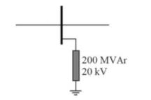
In the power bus of Fig. 1.6, the base voltage and power are \(20 \mathrm{kV}\) and \(100 \mathrm{MVA}\), respectively. If a reactor is connected to this bus, determine its reactance in per unit (p.u.).1) 0.25 2) 0.5 3) 0.75 4) 2 | 200 MVAr 20 kV
Figure 1.7 shows the single-line diagram of a power system with the following specifications. Calculate the resistance of the load in per unit (p.u.) if the nominal quantities of the generator are chosen as the base quantities:\[\mathrm{G}: 20 \mathrm{kV}, 300
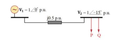
Figure 1.8 illustrates the single-line diagram of a power system with the given information. Calculate \(P\) and \(Q\) in per unit (p.u.). In this problem, assume that \(\sin \left(15^{\circ}ight) \equiv 0.25\) and \(\cos \left(15^{\circ}ight) \equiv 0.96\).1) \(P=0.5\) p.u., \(Q=0.08\) p.u.2)
Calculate the complex power delivered to a factory that includes two loads with the following specifications:\[\begin{gathered}\text { Inductive Load : } P_{1}=60 \mathrm{~kW}, Q_{1}=660 \mathrm{kVAr} \\\text { Capacitive Load : } P_{2}=240 \mathrm{~kW}, P F=0.8\end{gathered}\]1) \((180+j 840)
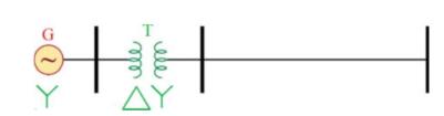
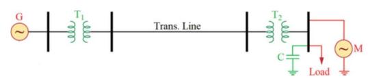
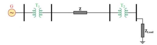
Figure 1.9 shows the single-line diagram of a balanced three-phase power system, in which a synchronous generator has been connected to a no-load transmission line through a transformer.Calculate the Thevenin reactance seen from the end of the transmission line. In this problem, the rated
For the three-phase power system of Fig. 1.10, the following specifications have been given. Determine the voltage drop of the line in percent:Line : \(\mathbf{Z}=(10+j 40) \Omega /\) phase Load : \(V=100 \mathrm{kV}, S=50 M V A, P F=0.8\) Lagging1) \(8 \%\)2) \(16 \%\)3) \(19 \%\)4) \(24 \%\) V Z
In the power system of Fig. 1.11, calculate the impedance of the load in per unit (p.u.) for the following specifications. In this problem, \(20 \mathrm{kV}\) (in the generator side) and 3 MVA are chosen as the base voltage and power:\[\begin{gathered}\mathrm{G}: 20 k V, 3 M V A, 3 \%
In the single-phase power bus of Fig. 1.12, the characteristics of the loads are as follows. Determine the total power factor of the bus:\[\begin{gathered}\text { Load } 1: P_{1}=25 k W, Q_{1}=25 k V A r \\\text { Load } 2: S_{2}=15 k V A, \cos \left(\theta_{2}ight)=0.8 \text { Leading } \\\text {
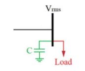
In the single-phase power bus of Fig. 1.13, determine the capacitance of the shunt capacitor that needs to be connected to the bus to adjust its power factor at one for the following data:\[\begin{gathered}\text { Load }: S=20 k V A, \cos (\theta)=0.8 \text { Lagging } \\V_{r m s}=200 V, f=50 H z,
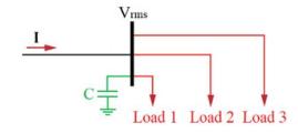
In the single-phase power system of Fig. 1.14, three loads have been connected to the power bus in parallel. Determine the capacitance of the shunt capacitor that needs to be connected to the bus to adjust its power factor at one for the following specifications. Moreover, calculate the current of
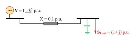
In the power system of Fig. 1.15, determine the reactive power of the shunt capacitor to keep the voltage of its bus at 1 p.u. In this problem, assume that \(\cos \left(\sin ^{-1}(0.1)ight) \equiv 0.995\).1) 1.05 p.u.2) 1.15 p.u.3) 1.5 p.u.4) 2.2 p.u. V=1/0 p.u. X=0.1 p.u. FTS Sload (1+j) p.u.
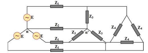
In the three-phase power system of Fig. 1.16, two balanced three-phase loads with the star and delta connections have been connected to a three-phase power supply. Calculate the line voltage of the loads for the following specifications:\[E_{r m s}=4 V, \mathbf{Z}_{\mathbf{1}}=j 2 \Omega,
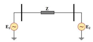
In the power system of Fig. 1.17, \(\delta=15^{\circ}\). If the value of \(\delta\) increases and \(E_{1}\) and \(E_{2}\) are kept constant, which one of the following choices is correct? In this problem, assume that \(\mathbf{I}_{\mathbf{1 2}}\) always lags \(\mathbf{E}_{\mathbf{2}}\) and
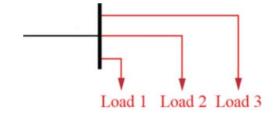
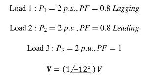
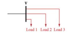
Three loads with the following specifications, resulted from the load flow simulation, have been connected to the power bus shown in Fig. 1.18. If all the loads are modeled by an admittance, determine it in per unit (p.u.):1) 6 p.u.2) \((2-j) p . u\)3) \((2+j) p . u\).4) \((2-j 2) p . u\). Load 1:
At the end of a three-phase power system, \(400 \mathrm{~V}, 50 \mathrm{~Hz}\), three capacitor banks (with triangle configuration) have been connected to the system. Determine the capacitance of each bank if they deliver \(600 \mathrm{kVAr}\) to the system.1) \(5000 \mu \mathrm{F}\)2) \(4000 \mu
The single-line diagram of a balanced three-phase power system is shown in Fig. 1.19. In this problem \(S_{B}=100 M V A\) and \(V_{B}=22 \mathrm{kV}\) in the first bus. Calculate the impedance seen from the first bus if the following specifications are given:\[\begin{gathered}\mathrm{G}: 22 k V, 90
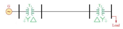
In the power system of Fig. 1.20, calculate the current of the load in per unit (p.u.) for the following specifications. In this problem, \(100 \mathrm{~V}\) (in the generator side) and \(1 \mathrm{kVA}\) are chosen as the base voltage and power:\[\mathrm{G}: 100 \mathrm{~V}\]\[\mathrm{T}_{1}: 200
For a set of linear algebraic equations in matrix format, \(\mathbf{A x}-\mathbf{y}\), for a unique solution to exist, \(\operatorname{det}(\mathbf{A})\) should be ___________.
For an \(N \times N\) square matrix \(\mathbf{A}\), in \((N-1)\) steps, the technique of Gauss elimination can transform into an ___________ matrix.
For the iterative solution to linear algebraic equations \(\mathbf{A x}-\mathbf{y}\), the \(\mathbf{D}\) matrix in the Jacobi method is the Gauss-Siedel is the __________ portion of \(\mathbf{A}\). portion of \(\mathbf{A}\), whereas \(\mathbf{D}\) for Gauss-Siedel is the __________ portion of
Is convergence guaranteed always with Jacobi and Gauss-Siedel methods, as applied to iterative solutions of linear algebraic equations?(a) Yes(b) No
For the iterative solutions to nonlinear algebraic equations with the Newton-Raphson method, the Jacobian matrix \(\mathbf{J}(i)\) consists of the partial derivatives. Write down the elements of first row of \(\mathbf{J}(i)\).
For the Newton-Raphson method to work, one should make sure that \(\mathbf{J}^{-1}\) exists.(a) True(b) False
The Newton-Raphson method in four steps makes use of Gauss elimination and back substitution.(a) True(b) False
The number of iterations required for convergence is dependent/independent of the dimension \(N\) for Newton-Raphson method. Choose one.
The swing bus or slack bus is a reference bus for which \(\mathrm{V}_{1} / \delta_{1}\), typically \(1.0 \angle 0^{\circ}\) per unit, is input data. The power flow program computes __________. Fill in the blank.
Most buses in a typical power flow program are load buses, for which \(\mathrm{P}_{k}\) and \(\mathrm{Q}_{k}\) are input data. The power flow program computes __________.
For a voltage-controlled bus \(k\), __________ are input data, while the power flow program computes __________.
When the bus \(k\) is a load bus with no generation and inductive load, in terms of generation and load, \(\mathrm{P}_{k}=\) __________, and \(\mathrm{Q}_{k}=\) __________.
Starting from a single-line diagram of a power system, the input data for a power flow problem consists of __________, __________, and __________.
Nodal equations \(\boldsymbol{I}=\boldsymbol{Y}_{\text {bus }} \boldsymbol{V}\) are a set of linear equations analogous to \(\boldsymbol{y}=\boldsymbol{A x}\).(a) True(b) False
Because of the nature of the power flow bus data, nodal equations do not directly fit the linear-equation format, and power flow equations are actually nonlinear. However, the Gauss-Siedel method can be used for the power flow solution.(a) True(b) False
The Newton-Raphson method is most well suited for solving the nonlinear power flow equations.(a) True(b) False
By default, PowerWorld Simulator uses __________ method for the power flow solution.
Prime-mover control of a generator is responsible for a significant change in __________, whereas excitation control significantly changes __________.
From the power flow standpoint, the addition of a shunt-capacitor bank to a load bus corresponds to the addition of a positive/negative reactive load. Choose the right word.
Tap-changing and voltage-magnitude-regulating transformers are used to control bus voltages and reactive power flows on lines to which they are connected.(a) True(b) False
A matrix, which has only a few nonzero elements, is said to be __________.
Sparse-matrix techniques are used in Newton-Raphson power flow programs in order to reduce computer __________ and __________ requirements.
Reordering buses can be an effective sparsity technique in power flow solutions.(a) True(b) False
While the fast decoupled power flow usually takes more iterations to converge, it is usually significantly faster than the Newton-Raphson method.(a) True(b) False
The "dc" power flow solution, giving approximate answers, is based on completely neglecting the \(\mathrm{Q}-\mathrm{V}\) equation and solving the linear real-power balance equations.(a) True(b) False
Using Gauss elimination, solve the following linear algebraic equations:\[\begin{aligned}-25 x_{1}+10 x_{2}+10 x_{3}+10 x_{4} & =0 \\5 x_{1}-10 x_{2}+10 x_{3} & =2 \\10 x_{1}+5 x_{2}-10 x_{3}+10 x_{4} & =1 \\10 x_{1}-20 x_{4} & =-2\end{aligned}\]
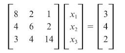
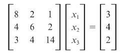
Using Gauss elimination and back substitution, solve 8 2 1 4 6 2 3 4 14 X X 3 4 2
Rework Problem 6.2 with the value of 8 changed to 4.Problem 6.2Using Gauss elimination and back substitution, solve 8 2 1 4 6 2 3 4 14 X X 3 4 2
What is the difficulty in applying Gauss elimination to the following linear algebraic equations?\[\begin{aligned}-5 x_{1}+5 x_{2} & =5 \\10 x_{1}-10 x_{2} & =-5\end{aligned}\]
Show that, after triangularizing \(\mathbf{A x}=\mathbf{y}\), the back substitution method of solving \(\mathbf{A}^{(N-1)} \mathbf{x}=\mathbf{y}^{(N-1)}\) requires \(N\) divisions, \(N(N-1) / 2\) multiplications, and \(N(N-1) / 2\) subtractions. Assume that all the elements of
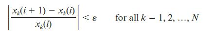
Solve Problem 6.2 using the Jacobi iterative method. Start with \(x_{1}(0)=\) \(x_{2}(0)=x_{3}(0)=0\), and continue until (6.2.2) is satisfied with \(\varepsilon=0.01\).Eq (6.2.2)Problem 6.2Using Gauss elimination and back substitution, solve x(i+1)-x(i) xx(i) < E for all k = 1, 2, ..., N
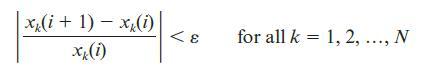
Repeat Problem 6.6 using the Gauss-Seidel iterative method. Which method converges more rapidly?Problem 6.6Using the Jacobi iterative method. Start with \(x_{1}(0)=\) \(x_{2}(0)=x_{3}(0)=0\), and continue until (6.2.2) is satisfied with \(\varepsilon=0.01\).Eq (6.2.2) x(i+1) x(i) xx(i) < E for all
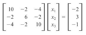
Express the following set of equations in the form of (6.2.6), and then solve using the Jacobi iterative method with \(\varepsilon=0.05\) and with \(x_{1}(0)=1\), and \(x_{2}(0)=1, x_{3}(0)=0\).Eq (6.2.6) 10 -2 -4 -2 6 -2 -4 -2 10 X2 X3 -2 3 1
Solve for \(x_{1}\) and \(x_{2}\) in the system of equations given by\[\begin{array}{r}x_{2}-3 x_{1}+1.9=0 \\x_{2}+x_{1}^{2}-3.0=0\end{array}\]using the Gauss method with an initial guess of \(x_{1}=1\) and \(x_{2}=1\).
Solve \(x^{2}-4 x+1=0\) using the Jacobi iterative method with \(x(0)=1\). Continue until (6.2.2) is satisfied with \(\varepsilon=0.01\). Check using the quadratic formula.
Try to solve Problem 6.2 using the Jacobi and Gauss-Seidel iterative methods with the value of \(\mathrm{A}_{33}\) changed from 14 to 0.14 and with \(x_{1}(0)=x_{2}(0)=\) \(x_{3}(0)=0\). Show that neither method converges to the unique solution.Problem 6.2Using Gauss elimination and back
Using the Jacobi method (also known as the Gauss method), solve for \(x_{1}\) and \(x_{2}\) in the following system of equations.\[\begin{array}{r}x_{2}-3 x_{1}+1.9=0 \\x_{2}+x_{1}^{2}-1.8=0\end{array}\]Use an initial guess of \(x_{1}(0)=1.0\) and \(x_{2}=(0)=1.0\). Also, see what happens when you
Use the Gauss-Seidel method to solve the following equations that contain terms that are often found in power flow equations.\[\begin{gathered}x_{1}=(1 /(-20 j)) *\left[(-1+0.5 j) /\left(x_{1}ight)^{*}-(j 10) * x_{2}-(j 10)ight] \\x_{2}=(1 /(-20 j)) *\left[(-3+j) /\left(x_{2}ight)^{*}-(j 10) *
Find a root of the following equation by using the Gauss-Seidel method: (use an initial estimate of \(x=2\) ) \(f(x)=x^{3}-6 x^{2}+9 x-4=0\).
Use the Jacobi method to find a solution to \(x^{2} \cos x-x+0.5=0\). Use \(x(0)=1\) and \(\varepsilon=0.01\). Experimentally determine the range of initial values that results in convergence.
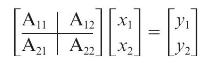
Determine the poles of the Jacobi and Gauss-Seidel digital filters for the general two-dimensional problem (N=2)(N=2) :Then determine a necessary and sufficient condition for convergence of these filters when N=2N=2. xi]]Au| A [A | A 21 12 X? ]-]
Use Newton-Raphson to find a solution to the polynomial equation \(f(x)=y\) where \(y=0\) and \(f(x)=x^{3}+8 x^{2}+2 x-40\). Start with \(x(0)=1\) and continue until (6.2.2) is satisfied with \(\varepsilon=0.001\).
Showing 3300 - 3400
of 5433
First
27
28
29
30
31
32
33
34
35
36
37
38
39
40
41
Last
Step by Step Answers