New Semester
Started
Get
50% OFF
Study Help!
--h --m --s
Claim Now
Question Answers
Textbooks
Find textbooks, questions and answers
Oops, something went wrong!
Change your search query and then try again
S
Books
FREE
Study Help
Expert Questions
Accounting
General Management
Mathematics
Finance
Organizational Behaviour
Law
Physics
Operating System
Management Leadership
Sociology
Programming
Marketing
Database
Computer Network
Economics
Textbooks Solutions
Accounting
Managerial Accounting
Management Leadership
Cost Accounting
Statistics
Business Law
Corporate Finance
Finance
Economics
Auditing
Tutors
Online Tutors
Find a Tutor
Hire a Tutor
Become a Tutor
AI Tutor
AI Study Planner
NEW
Sell Books
Search
Search
Sign In
Register
study help
computer science
systems analysis design
The Analysis And Design Of Linear Circuits 10th Edition Roland E. Thomas, Albert J. Rosa, Gregory J. Toussaint - Solutions
Use Multisim to show the power balance in the circuit of P2–51, that is, that the sum of the power in the circuit equals zero. DVI IA 10 22 + 15 92 301 ww
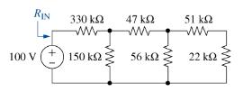
Consider the circuit of Figure P2-63 .(a) Use MATLAB to find all of the voltages and currents in the circuit and find the power provided by the source.(b) Use MATLAB to find the input resistance that the source sees, \(R_{\text {IN }}\). RIN 330 100 V ( ) 150 47 56 51 22
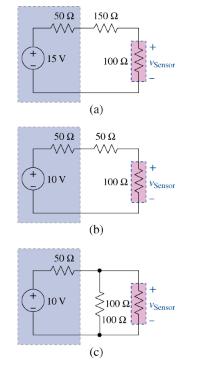
You are a head intern overseeing three junior interns. A sensor that is modeled by a \(100-\Omega\) resistor requires five volts to operate correctly. You ask the three interns to design a power circuit for the sensor. Their designs are shown in Figure P2-64. The sources all have a \(50-\Omega\)
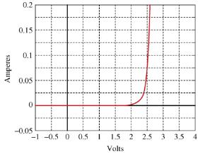
The circuit in Figure P2-65 is a parallel combination of a \(75-\Omega\) linear resistor and a varistor whose \(i-v\) characteristic is \(i_{\mathrm{V}}=\) \(38 \times 10^{-3} v^{3}\). For a small voltage, the varistor current is quite small compared to the resistor current. For large voltages, the
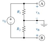
Figure P2-66 shows a voltage divider with the center tap connected to ground. Derive equations relating \(v_{\mathrm{A}}\) and \(v_{\mathrm{B}}\) to \(v_{\mathrm{S}}\) , \(R_{1}\), and \(R_{2}\). VS + R R VA 191 VB A (B
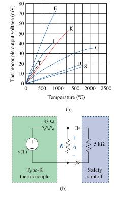
A type- \(\mathrm{K}\) thermocouple produces a voltage that is proportional to temperature. The characteristic of a type-K thermocouple is shown in Figure P2-67. (a). In an application, this transducer is used to detect when the temperature reaches \(1250^{\circ} \mathrm{C}\) and then to cause a
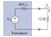
Figure P2-68 shows an active transducer whose resistance \(R\) ( \(V\) \(\left.{ }_{\mathrm{T}}ight)\) varies with the transducer voltage \(V_{\mathrm{T}}\) as \(R\left(V_{\mathrm{T}}ight)=0.5 V_{\mathrm{T}}{ }^{2}+\) 1. The transducer supplies a current to a 12- \(\Omega\) load. At what voltage
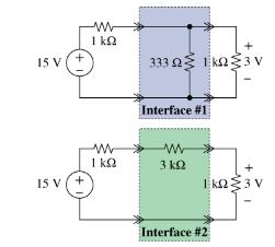
You have a practical current source that can be modeled as a 15-V ideal source in series with a 1-kΩ source resistor. You need to use your source to drive a 1-kΩ load that requires exactly 3 V across it. Two solutions are provided to you as shown in Figure P2–69. Validate that both meet the
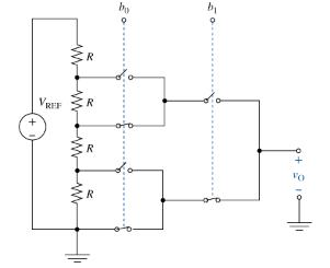
Figure P2-70 shows a programmable voltage divider in which digital inputs \(b_{0}\) and \(b_{1}\) control complementary analog switches connecting a multitap voltage divider to the analog output \(v_{\mathrm{O}}\). The switch positions in the figure apply when digital inputs are low. When inputs go
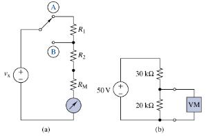
Figure P2-71 (a) shows a voltmeter circuit consisting of a D'Arsonval meter, two series resistors, and a two-position selector switch. A current of \(I_{\mathrm{FS}}=400 \mu \mathrm{A}\) produces full-scale deflection of the D'Arsonval meter, whose internal resistance is \(R_{\mathrm{M}}=25
MATLAB Function for Parallel Equivalent ResistorsCreate a MATLAB function to compute the equivalent resistance of a set of resistors connected in parallel. The function has a single input, which is a vector containing the values of all of the resistors in parallel, and it has a single output, which
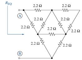
Finding an Equivalent Resistance Using MultisimUse Multisim to find the equivalent resistance at terminals A and B of the resistor mesh shown in Figure P2-7.3 . Schematic illustration of create a MATLAB function to compute the equivalent resistance of a set of resistors connected in parallel. REQ
An all-electric roadster requires a battery module that can deliver \(375 \mathrm{~V}\) and \(90 \mathrm{kWh}\). A battery manufacturer can deliver a single Li-ion cell that produces 3.7 V at \(3400 \mathrm{mAh}\). Design a suitable module by combining sufficient cells to meet the specification.
Formulate node-voltage equations for the circuit in Figure P3-1 . Arrange the results in matrix form \(\mathbf{A x}=\mathbf{b}\). R VB R www R VC R www
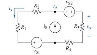
(a) Formulate node-voltage equations for the circuit in Figure \(\mathrm{P}_{3} \mathbf{- 2}\). Arrange the results in matrix form \(\mathbf{A x}=\mathbf{b}\).(b) Solve these equations for \(o_{\mathrm{A}}\) and \(v_{\mathrm{B}}\).(c) Use these results to find \(v_{\mathrm{x}}\) and
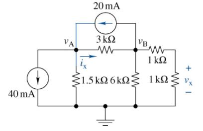
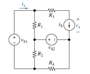
(a) Formulate node-voltage equations for the circuit in Figure \(\mathrm{P}_{3}=3\).(b) Solve these equations for \(v_{\mathrm{A}}\) and \(v_{\mathrm{B}}\).(c) Use these results to find \(v_{\mathrm{x}}\) and \(i_{\mathrm{x}}\). 40 mA VA 20 mA 3 1.5k 6 VB 1
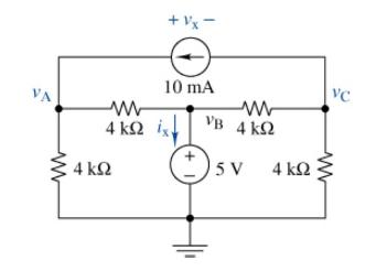
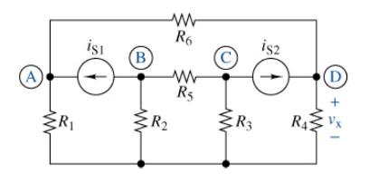
(a) Formulate node-voltage equations for the circuit in Figure P3-4. Arrange the results in matrix form \(\mathbf{A x}=\mathbf{b}\).(b) Solve these equations for \(v_{\mathrm{A}}\) and \(v_{\mathrm{C}}\).(c) Use these results to find \(v_{\mathrm{x}}\) and \(i_{\mathrm{x}}\). 4 4 + 1x = 10 mA VB
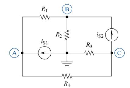
The following are a set of node-voltage equations; draw the circuit they represent.\[\begin{aligned}v_{\mathrm{A}} & =v_{\mathrm{S}} \\\frac{v_{\mathrm{B}}-v_{\mathrm{A}}}{R_{1}}+\frac{v_{\mathrm{B}}-v_{\mathrm{C}}}{R_{2}}-i_{\mathrm{S}} & =0
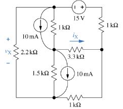
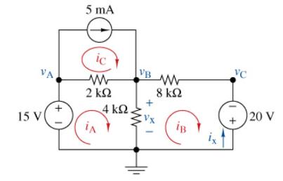
(a) Choose a ground wisely and formulate node-voltage equations for the circuit in Figure P \(3=6\).(b) Solve for \(v_{\mathrm{x}}\) and \(i_{\mathrm{x}}\).(c) Validate your answers using Multisim. 10 mA VX 2.2 1.5 15V 1.3.3 10 mA ww
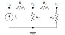
(a) Formulate node-voltage equations for the circuit in Figure P3=7.(b) Use MATLAB to find symbolic expressions for the node voltages in terms of the parameters in the circuit.(c) Find numeric values for \(v_{\mathrm{A}}, v_{\mathrm{B}}\), and \(v_{\mathrm{C}}\) when \(R_{1}=10\) \(\mathrm{k}
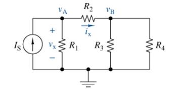
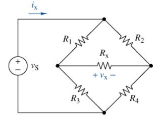
(a) Formulate node-voltage equations for the bridge circuit in Figure \(\mathrm{P}_{3}-8\).(b) Solve for \(v_{\mathrm{x}}\) and \(i_{\mathrm{x}}\) when \(R_{1}=R_{4}=1 \mathrm{k} \Omega, R_{2}=R_{3}=\) \(1.5 \mathrm{k} \Omega, R_{\mathrm{X}}=680 \Omega\), and \(v_{\mathrm{S}}=12 \mathrm{~V}\).(c)
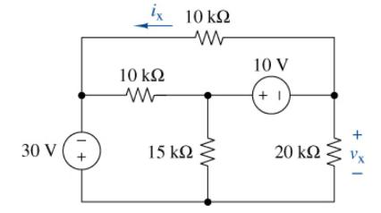
(a) Formulate node-voltage equations for the circuit in Figure P3=9.(b) Solve for \(v_{\mathrm{X}}\) and \(i_{\mathrm{x}}\).(c) Verify your results using Multisim. 30 V 1 + 1x 10 10 15 10 V +1 20 +1
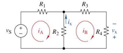
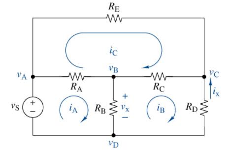
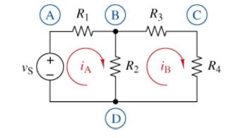
(a) Formulate mesh-current equations for the circuit in Figure \(\mathrm{P}_{3}-10\). Arrange the results in matrix form \(\mathbf{A x}=\mathbf{b}\).(b) Solve for \(i_{\mathrm{A}}\) and \(i_{\mathrm{B}}\).(c) Use these results to find \(v_{\mathrm{x}}\) and \(i_{\mathrm{x}}\). VS +1 R iA R2 R3 ww
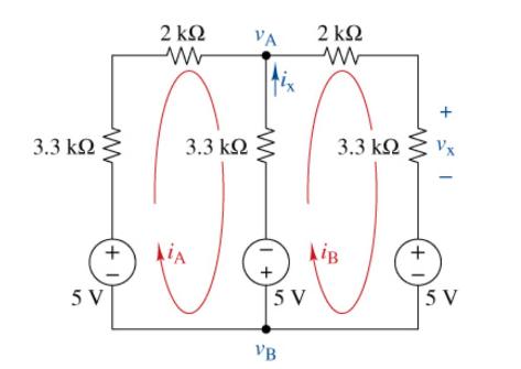
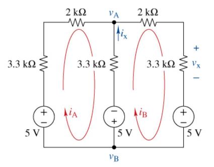
(a) Formulate mesh-current equations for the circuit in Figure P3-11. Arrange the results in matrix form \(\mathbf{A x}=\mathbf{b}\).(b) Solve for \(i_{\mathrm{A}}\), and \(i_{\mathrm{B}}\).(c) Use these results to find \(v_{\mathrm{x}}\) and \(i_{\mathrm{x}}\). 3.3 (+1) 5V 2 3.3 AiA VA 2
Sometimes intuition is simpler than using either meshcurrent or node-voltage analysis. Reduce the circuit in Figure \(\underline{P}_{3}-11\) into a single loop and find the voltage between \(v_{\mathrm{a}}\) and \(v_{\mathrm{b}}\) 3.3 5 V +1 2 3.3 AIA VA +1 5V VB 2 3.3 AiB +1 5V
(a) Formulate mesh-current equations for the circuit in Figure P3-13 .(b) Formulate node-voltage equations for the circuit in Figure P3-13.(c) Which set of equations would be easier to solve? Why?(d) Using MATLAB, find \(v_{\mathrm{x}}\) and \(i_{\mathrm{x}}\) in terms of the meshcurrent
(a) Formulate mesh-current equations for the circuit in Figure P3-14 . ( Hint: Use a supermesh.)(b) Reduce the circuit to one node using source transformations and solve for the node voltage \(v_{\mathrm{A}}\).(c) Solve for \(v_{\mathrm{x}}\) and \(i_{\mathrm{x}}\) when \(R_{1}=2.7 \mathrm{k}
(a) Formulate mesh-current equations for the circuit in Figure \(\mathrm{P}_{3}-15\).(b) Use MATLAB to find symbolic expressions for \(v_{\mathrm{x}}\) and \(i\) \(x\) in terms of the parameters in the circuit.(c) Find numeric values for \(v_{\mathrm{x}}\) and \(i_{\mathrm{x}}\) when
The circuit in Figure P3-16 seems to require two supermeshes since both current sources appear in two meshes. However, sometimes rearranging the circuit diagram will eliminate the need for a supermesh.(a) Show that supermeshes can be avoided in Figure P3-16 by rearranging the connection of resistor
(a) Formulate mesh-current equations for the circuit in Figure \(\mathrm{P}_{3}=17\).(b) Formulate node-voltage equations for the circuit in Figure P3-17.(c) Which set of equations would be easier to solve? Why?(d) Find \(v_{\mathrm{x}}\) and \(i_{\mathrm{x}}\) using whichever method you prefer. VA
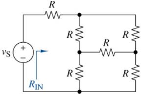
Use simple engineering intuition to find the input resistance of the circuit in Figure P \(3-18\). Use either nodevoltage or mesh-current analysis to prove your intuition. vs R ww RIN R R ww R www R ww
Use Figure P3-19 and MATLAB to solve the following problems:(a) Using mesh-current analysis, find a symbolic expression for \(i_{\mathrm{A}}\) in terms of the circuit parameters.(b) Compute the ratio \(v_{\mathrm{S}} / i_{\mathrm{A}}\).(c) Find a symbolic expression for the equivalent resistance of
(a) Formulate mesh-current equations for the circuit in Figure P \(3=20\).(b) Formulate node-voltage equations for the circuit in Figure \(\mathrm{P}_{3}=\mathbf{2 0}\).(c) Which set of equations would be easier to solve? Why?(d) Use Multisim to find the node voltages \(v_{\mathrm{A}}\) and
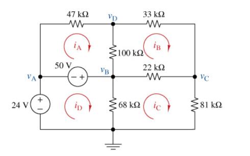
(a) Formulate mesh-current equations for the circuit in Figure P 3 -21 . Arrange the results in matrix form \(\mathbf{A x}=\mathbf{b}\).(b) Use MATLAB and mesh-current analysis to solve for the mesh currents \(i_{\mathrm{A}}, i_{\mathrm{B}}, i_{\mathrm{C}}\), and \(i_{\mathrm{D}}\).(c) Formulate
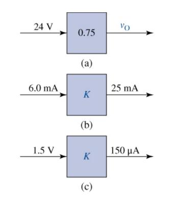
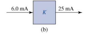
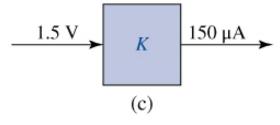
(a) Find \(v_{\mathrm{O}}\) for the block diagram shown in Figure \(\mathrm{P}_{3} \mathbf{- 2 2}\) (a).(b) Find the proportionality constant \(K\) for the circuit in Figure P3-22 (b).(c) Find the proportionality constant \(K\) for the circuit in Figure P3-22 (c). 24 V 6.0 mA 1.5 V 0.75 (a) K (b) K
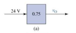
Design a voltage-divider circuit that will realize the block diagram in Figure \(\mathrm{P}_{3} \mathbf{- 2 2}\) (a). 24 V 0.75 (a) Vo
Design a current-divider circuit that will realize the block diagram in Figure P3-22 (b). 6.0 mA K (b) 25 mA
Using a single resistor, design a circuit that will realize the block diagram in Figure P3-22 (c). 1.5 V K (c) 150
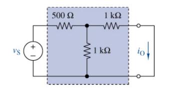
(a) Find the proportionality constant \(K=i_{\mathrm{O}} / v_{\mathrm{S}}\) for the circuit in Figure P3-26 .(b) What are the units associated with the \(K\) you found?.(c) If \(v_{\mathrm{S}}=10 \mathrm{~V}\), what is \(i_{\mathrm{O}}\) ?. VS +1 500 1
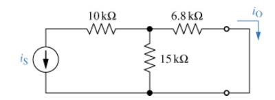
(a) Find the proportionality constant \(K=i_{\mathrm{O}} / i_{\mathrm{S}}\) for the circuit in Figure P 3 -27.(b) Replace the current source with a voltage source plus side up, and find \(K=i_{\mathrm{O}} / v_{\mathrm{S}}\). is 10k 6.8 15 io
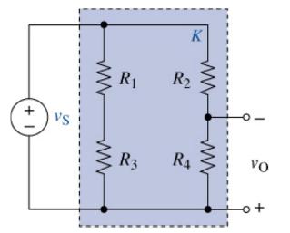
Find the proportionality constant \(K=v_{\mathrm{O}} / v_{\mathrm{S}}\) for the circuit in Figure \(\mathrm{P} 3-28\). Then select values for the resistors so that \(v_{\mathrm{O}}\) is \(-01 v_{\mathrm{S}}\). +1 VS R R3 K R R4 VO
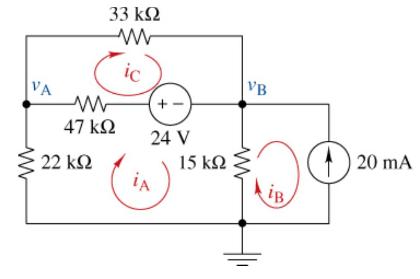
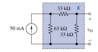
Use the unit output method to find \(K\) and \(v_{\mathrm{O}}\) in Figure P3-29. 50 mA 33 k 63 33 VO
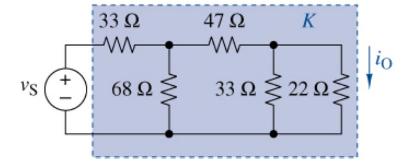
Use the unit output method to find \(K\) in Figure P \(_{3}=3\) O . Then select a value for \(v_{\mathrm{S}}\) that will produce an output current of \(i_{\mathrm{O}}=250 \mathrm{~mA}\). Vs +1 133 68 47 33 22 K
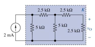
Use the unit output method to find \(K\) in Figure \(\underline{P}_{3}=3 \underline{1}\) . Then find \(v_{\mathrm{O}}\) for the input provided. 2 mA 2.5 5 2.5 5 2.5 K VO
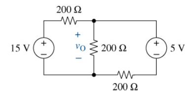
Use the superposition principle to find \(v_{\mathrm{O}}\) in Figure P \(_{3}=\) 32 . 15 V | 200 VO | 200 200 +1) 5V
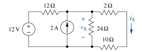
Use the superposition principle to find \(v_{\mathrm{X}}\) and \(i_{\mathrm{X}}\) in Figure P \(_{3}=33\). 12V 12 2 VX 2 24 10
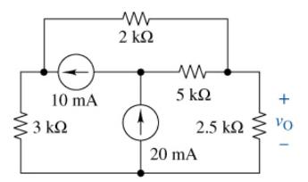
Use the superposition principle to find \(v_{\mathrm{O}}\) in Figure \(\mathrm{P}_{3}=\) 34 . 10 mA 3 2 M 5 2.5 20 mA + VO
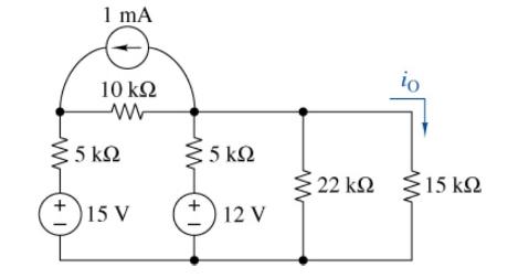
Use the superposition principle to find \(i_{\mathrm{O}}\) in Figure P \(_{3}=35\). Verify your answer using Multisim. 1 mA (+1) 10 : 5 15 V 5 5 +1 | 12 V io 22 15
A linear circuit containing two sources drives a 100- \(\Omega\) load resistor. Source number 1 delivers \(1 \mathrm{~W}\) to the load when source number 2 is off. Source number 2 delivers \(9 \mathrm{~W}\) to the load when source number 1 is off. Find the power delivered to the load when both
A block diagram of a linear circuit is shown in Figure P \(3=37\). When \(v_{\mathrm{S}}=20 \mathrm{~V}\) and \(i_{\mathrm{S}}=40 \mathrm{~mA}\), the output voltage \(v_{\mathrm{O}}\) \(=20 \mathrm{~V}\). The output voltage is \(80 \mathrm{~V}\) when the voltage source is off or
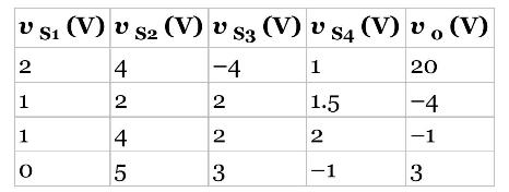
A certain linear circuit has four input voltages and one output voltage \(v_{\mathrm{O}}\). The following table lists the output for different values of the four inputs. Find the input-output relationship for the circuit. Specifically, find an expression for \(v\) o in terms of the four input
For the circuit in Figure P \(3=39\), find the Thévenin and Norton equivalent circuits. 100 | 50 V 150 www 150 Wy, RT. IN
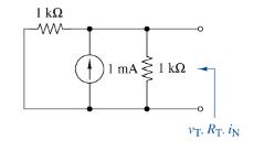
For the circuit in Figure P3-4응 find the Thévenin and Norton equivalent circuits. 11 MA 0 VT. Ry. N
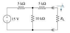
(a) Find the Thévenin or Norton equivalent circuit seen by \(R_{\mathrm{L}}\) in Figure \(\mathrm{P}_{3}=4 \underline{1}\).(b) Select a \(5 \%\) value of \(R_{\mathrm{L}}\) from Appendix \(\mathrm{G}\) that will result in an \(i_{\mathrm{L}}\) of \(1 \mathrm{~mA} \pm 5 \%\). Show that the
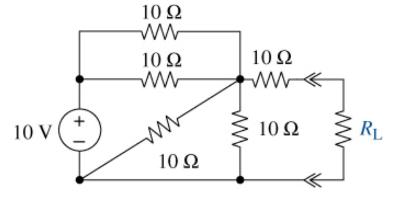
(a) Find the Thévenin equivalent circuit seen by \(R_{\mathrm{L}}\) in Figure \(\mathrm{P}_{3}=4 \underline{2}\).(b) Repeat (a) using Multisim.(c) Find the voltage across the load and the power delivered to it when \(R_{\mathrm{L}}=5 \Omega, 12.5 \Omega\), and \(20 \Omega\). 10 V ( + 1, 10 10
Find the Norton equivalent seen by \(R_{\mathrm{L}}\) in Figure \(\mathrm{P}_{3}=\) 43 . Find the current through the load when \(R_{\mathrm{L}}=5 \mathrm{k} \Omega, 10 \mathrm{k} \Omega\), and \(47 \mathrm{k} \Omega\). 10 10 mA 10 10 RL
The Thévenin equivalent parameters of a two-terminal source are \(v_{\mathrm{T}}=5 \mathrm{~V}\) and \(R_{\mathrm{T}}=150 \Omega\). Find the minimum allowable load resistance if the delivered load voltage must exceed \(3.5 \mathrm{~V}\).
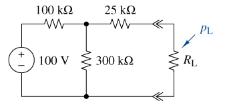
(a) Create the circuit shown in Figure P3-45 in Multisim. Do a parameter sweep of the load resistor \(R_{\mathrm{L}}\) (arbitrarily set to \(1 \mathrm{k} \Omega\) ) from \(1 \mathrm{k} \Omega\) to \(10 \mathrm{M} \Omega\) and plot its power \(p_{\mathrm{L}}\). Using the cursor find the value of
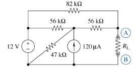
(a) Use Multisim to find the Norton equivalent at terminals \(A\) and B in Figure P \(3=4 \underline{6}\).(b) Use the Norton equivalent circuit found in part (a) to determine the power dissipated in \(R_{\mathrm{L}}\) when it is equal to 37 \(\mathrm{k} \Omega\).(c) Use Multisim to simulate both
The circuit in Figure P \(3=4\).7. was solved earlier using superposition (Problem 3-34). In this problem solve for the voltage across the load resistor \(v_{\mathrm{L}}\) by first finding the Thévenin equivalent circuit seen by the load resistor. Find \(v_{\mathrm{L}}\) when \(R_{\mathrm{L}}=\)
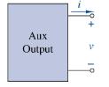
Assume that Figure P3-4 4 represents a model of the auxiliary output port of a car. The output current is \(i=2 \mathrm{~A}\) when measured by a very low-resistance ammeter. The voltage is \(V=\) \(12 \mathrm{~V}\) when measured by a very high-input resistance voltmeter. Suppose you wanted to
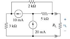
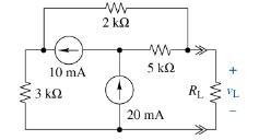
The \(i-v\) characteristic of the active circuit represented by Figure P \(3=4 \underline{8}\) is \(5 v+500 i=100\). Find the output voltage when a 100- \(\Omega\) resistive load is connected. 10 mA 13 2 5 k 20 mA R + VL
You have successfully completed the first course in Circuits I, and as part of an undergraduate work-study program your former professor has asked you to help her grade a Circuits I quiz. On the quiz, students were asked to find the power supplied by the source both to the \(10-\mathrm{k} \Omega\)
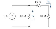
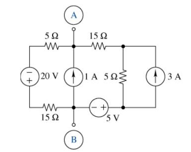
(a) Use a sequence of source transformations and the lookback method to find the Thévenin equivalent at terminals A and B in Figure P \(3=51\).(b) Then select a resistor to connect across A and B so that \(3 \mathrm{~V}\) appears across it.(c) Suppose the 1-A current source is replaced by an ideal
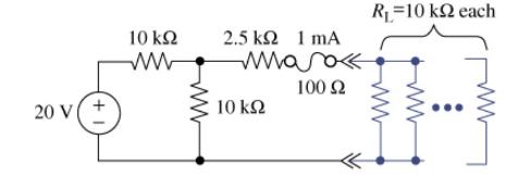
The circuit in Figure P3=52 provides power to a number of loads connected in parallel. The circuit is protected by a 1-mA fuse with a nominal \(100-\Omega\) resistance. Each load is \(10 \mathrm{k} \Omega\). What is the maximum number of loads the circuit can drive without blowing the fuse? 20 V (
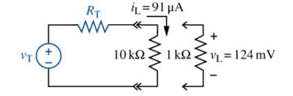
You need to determine the Thévenin equivalent circuit of a more complex linear circuit. A technician tells you she made two measurements using her DMM on the circuit. The first was with a \(10-\mathrm{k} \Omega\) load and the load current \(i_{\mathrm{L}}\) was \(91 \mu \mathrm{A}\); the second
A blue LED is connected across a two-terminal source whose Thévenin equivalent is \(v_{\mathrm{T}}=3 \mathrm{~V}\) and \(R_{\mathrm{T}}=10 \Omega\). The \(i-v\) characteristic of the LED is \(i=10^{-12}\left(e^{10 v}-1ight)\). Figure P \(_{3}=54\) shows the LED's \(i-v\) characteristic. Using
A non-linear device has the following \(i-v\) characteristics \(i=2.6 \times 10^{-5} v^{3}\). It is connected to a Thévenin circuit with a \(v_{\mathrm{T}}=150 \mathrm{~V}\) and an \(R_{\mathrm{T}}=8 \Omega\). Using MATLAB find the current through and the voltage across the non-linear device.
Find the Norton equivalent seen by \(R_{\mathrm{L}}\) in Figure \(\mathrm{P}_{3}=5 \underline{6}\).Select the value of \(R_{\mathrm{L}}\) so that(a) \(3 \mathrm{~V}\) is delivered to the load.(b) \(300 \mathrm{~mA}\) is delivered to the load.(c) \(100 \mathrm{~mW}\) is delivered to the load.
For the circuit of Figure \(\mathrm{P}_{3}=57\), find the value of \(R_{\mathrm{L}}\) that will result in(a) Maximum voltage. What is that voltage?(b) Maximum current. What is that current?(c) Maximum power. What is that power?
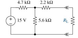
For the circuit of Figure \(\mathrm{P}_{3}=5 \underline{8}\), find the value of \(R_{\mathrm{L}}\) that will result in:(a) Maximum voltage. What is that voltage?(b) Maximum current. What is that current?(c) Maximum power. What is that power? +1) 4.7 | 15 V 2.2 5.6 RL
The resistance \(R\) in Figure P3=59. is adjusted until maximum power is delivered to the load consisting of \(R\) and the \(12-\mathrm{k} \Omega\) resistor in parallel.(a) Find the required value of \(R\).(b) How much power is delivered to the load?(c) Validate your answer using Multisim.(d) How
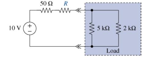
Find the value of \(R\) in the circuit of Figure \(\mathrm{P}_{3}-60\) so that maximum power is delivered to the load. What is the value of the maximum power? 10 V + 50 R 5 2 Load
Express the following quantities to the nearest standard prefix using no more than three digits.(a) \(3600 \mathrm{~s}\)(b) \(5 \times 10^{13} \mathrm{~W}\)(c) \(850,000 \mathrm{~Hz}\)(d) \(68 \times 10^{-12} \mathrm{~F}\)
Express the following quantities to the nearest standard prefix using no more than three digits.(a) \(0.00067 \mathrm{~A}\)(b) \(5.67 \times 10^{-3} \mathrm{H}\)(c) \(1,850,000 \mathrm{C}\)(d) \(33,330 \Omega\)
An ampere-hour (Ah) meter measures the time integral of the current in a conductor. During an 8-hour period, a certain meter records \(5400 \mathrm{Ah}\). Find the number of coulombs that flowed through the meter during the recording period.
Fill in the blanks in the following statements.(a) To convert capacitance from femtofarads to microfarads, multiply by(b) To convert resistance from megohms to kilohms, multiply by_____________.(c) To convert voltage from millivolts to volts, multiply by_____________.(d) To convert frequency from
Place in increasing value the following:(a) \(1500 \mathrm{~m} \Omega\)(b) \(0.1632 \Omega\)(c) \(0.00112 \mathrm{k} \Omega\)(d) \(0.0000016 \mathrm{M} \Omega\)
The net positive charge flowing through a device is \(q(t)=\) \(20+4 t \mathrm{mC}\). Find the current through the device.
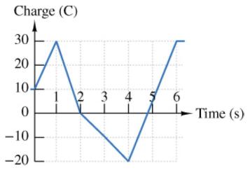
Figure P1-7. shows a plot of the net positive charge flowing in a wire versus time. Sketch the corresponding current during the same period of time. Charge (C) 30 20 10- 0 -10 -20 L 2 3 4 6 -Time (s)
The net negative charge flowing through a device varies as \(q\) \((t)=5.0 t^{2} \mathrm{C}\). Find the current through the device at \(t=0,1.0\), and \(2.0 \mathrm{~s}\).
The charge flowing through a device is \(q(t)=1-e^{-}\) \(1000{ }^{t} \mu \mathrm{C}\). What will the current be after \(1.6094 \mathrm{~ms}\) ?
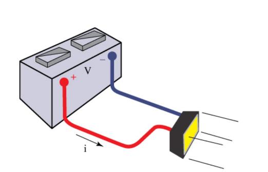
The \(12-V\) automobile battery in Figure \(\mathrm{P}_{1-10}\) has an output capacity of 100 Ah when connected to a head lamp that absorbs \(200 \mathrm{~W}\) of power. The car engine is not running and therefore not charging the battery. Assume the battery voltage remains constant.(a) Find the
The current through a device is zero for \(t
When illuminated the \(i-v\) relationship for a photocell is \(i=\) \(e^{v}-10 \mathrm{~A}\). For \(v=-2,1\), and \(2.5 \mathrm{~V}\), find the device power and state whether it is absorbing or delivering power.
The maximum current allowed by a device's power rating is limited by a \(10-\mathrm{mA}\) fuse. When the device is connected to a \(5-\mathrm{V}\) source, what is the maximum power the device can dissipate?
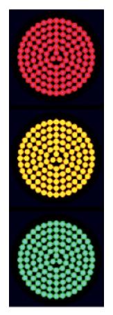
Traffic lights are being converted from incandescent bulbs to LED arrays to save operating and maintenance costs. Typically, each incandescent light uses three \(116-\mathrm{W}\) bulbs, one for each color R, Y, and G. A competing LED array consists of \(106 \mathrm{LEDs}\) with each LED requiring
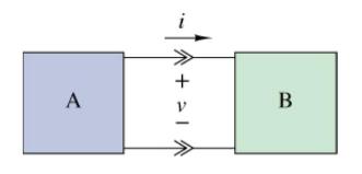
Two electrical devices are connected as shown in Figure \(\mathrm{P} 1-15\). Using the reference marks shown in the figure, find the power transferred and state whether the power is transferred from A to B or B to A when(a) \(v=+12 \mathrm{~V}\) and \(i=-1.2 \mathrm{~A}\)(b) \(v=+80 \mathrm{~V}\)
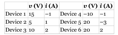
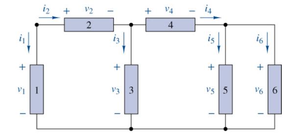
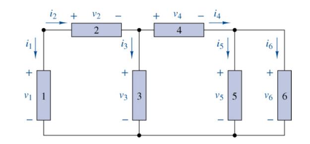
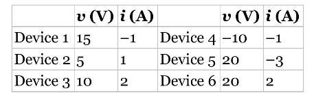
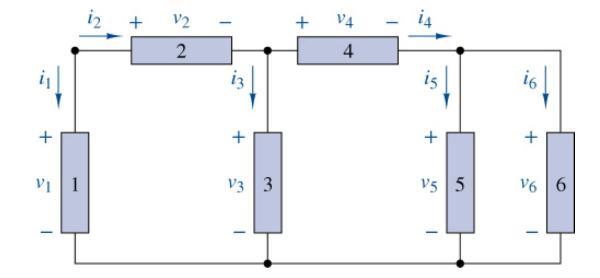
Figure P1-16 shows an electric circuit with a voltage and a current variable assigned to each of the six devices. The device voltages and currents are observed to be as follows:Find the power associated with each device and state whether the device is absorbing or delivering power. Use the power
Figure P1-16 shows an electric circuit with a voltage and a current variable assigned to each of the six devices. Use power balance to find \(v_{4}\) when \(v_{1}=24 \mathrm{~V}, i_{1}=-2.1 \mathrm{~A}, p_{2}=30\) \(\mathrm{W}, p_{3}=10 \mathrm{~W}, i_{4}=1.07 \mathrm{~A}\), and \(p_{5}=p_{6}=2.5
An ion implanter is used to accelerate electrons to crash into a silicon wafer to study the effects of electron radiation damage on the devices on the wafer. If the beam carries \(10^{16}\) electrons per second and is accelerated by a \(350 \mathrm{kV}\) source, find the current and power in the
Repeat Problem 1-16 using MATLAB to perform the calculations. Create a vector for the voltage values, \(v=\left[\begin{array}{ll}15 & 5\end{array}ight.\) 10-10 20 20 \(]\), and a vector for the current values, \(i=\left[\begin{array}{lll}-1 & 1 & 2\end{array}ight.\)
A stereo amplifier takes the output of a CD player, for example, and increases the power to an audible level. Suppose the output of the CD player is \(25 \mathrm{~mW}\) and the desired audible output is 100 \(\mathrm{W}\) per stereo channel, find the power ratio of the amplifier per channel in
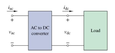
A manufacturer's data sheet for the converter in Figure P1-21 states that the output voltage is \(v_{\mathrm{dc}}=12 \mathrm{~V}\) when the input voltage \(v_{\mathrm{ac}}=120 \mathrm{~V}\). When the load draws a current \(i_{\mathrm{dc}}=18 \mathrm{~A}\), the input power is \(p_{\text {ac }}=360
A capacitor is a two-terminal device that can store electric charge. In a linear capacitor, the amount of charge stored is proportional to the voltage across the device. For a particular device the proportionality is \(q(t)=10^{-7} v(t)\). If \(v(t)=0\) for \(t\) \(
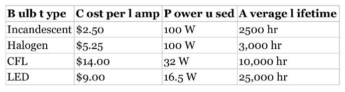
You need to provide sufficient light for a work area, and you determine that 1600 lumens would be adequate. You discover that there are four competing light sources that can deliver that amount of light: a \(100 \mathrm{~W}\) incandescent bulb, a \(100 \mathrm{~W}\) halogen bulb, a \(32
A circuit consists of five voltages, namely, \(v_{\mathrm{a}}, v_{\mathrm{b}}, v_{\mathrm{c}}, v_{\mathrm{d}}\), and \(v_{\mathrm{e}}\). The voltage from \(v_{\mathrm{a}}\) to \(v_{\mathrm{b}}\) is \(-5 \mathrm{~V}\), from \(v_{\mathrm{b}}\) to \(v_{\mathrm{c}}\) is \(10 \mathrm{~V}\), from
The current through a \(47-\mathrm{k} \Omega\) resistor is \(2.2 \mathrm{~mA}\). Find the voltage across the resistor.
The voltage across a particular resistor is \(8.85 \mathrm{~V}\) and the current is \(305 \mu \mathrm{A}\). What is the actual resistance of the resistor? Using Appendix G, what is the likely standard value of the resistor, if the resistor's tolerance is \(5 \%, 10 \%\), or \(20 \%\) ?
You can choose to connect either a \(3.3-\mathrm{k} \Omega\) resistor or a \(33-\mathrm{k} \Omega\) resistor across a \(5-\mathrm{V}\) source. Which will draw the least current from the source? What is that current?
Showing 4400 - 4500
of 5433
First
38
39
40
41
42
43
44
45
46
47
48
49
50
51
52
Last
Step by Step Answers