New Semester
Started
Get
50% OFF
Study Help!
--h --m --s
Claim Now
Question Answers
Textbooks
Find textbooks, questions and answers
Oops, something went wrong!
Change your search query and then try again
S
Books
FREE
Study Help
Expert Questions
Accounting
General Management
Mathematics
Finance
Organizational Behaviour
Law
Physics
Operating System
Management Leadership
Sociology
Programming
Marketing
Database
Computer Network
Economics
Textbooks Solutions
Accounting
Managerial Accounting
Management Leadership
Cost Accounting
Statistics
Business Law
Corporate Finance
Finance
Economics
Auditing
Tutors
Online Tutors
Find a Tutor
Hire a Tutor
Become a Tutor
AI Tutor
AI Study Planner
NEW
Sell Books
Search
Search
Sign In
Register
study help
computer science
systems analysis design
The Analysis And Design Of Linear Circuits 10th Edition Roland E. Thomas, Albert J. Rosa, Gregory J. Toussaint - Solutions
Reconsider Problem 5.7 and find the following:(a) sending-end power factor,(b) sending-end three-phase power, (c) the three-phase line loss.Problem 5.7The per-phase impedance of a short three-phase transmission line is 0.5/53.15∘Ω0.5/53.15∘Ω. The three-phase load at the receiving end is
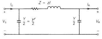
The 100−km,230−kV,60−Hz100−km,230−kV,60−Hz, three-phase line in Problems 4.18 and 4.39 delivers 300MVA300MVA at 218kV218kV to the receiving end at full load. Using the nominal ππ circuit, calculate the ABCDABCD parameters, sending-end voltage, and percent voltage regulation when the
The 500-kV, 60-Hz, three-phase line in Problems 4.20 and 4.41 has a \(180-\mathrm{km}\) length and delivers \(1600 \mathrm{MW}\) at \(475 \mathrm{kV}\) and at 0.95 power factor leading to the receiving end at full load. Using the nominal \(\pi\) circuit, calculate the(a) \(A B C D\) parameters,(b)
A \(40-\mathrm{km}, 220-\mathrm{kV}, 60-\mathrm{Hz}\), three-phase overhead transmission line has a per-phase resistance of \(0.15 \Omega / \mathrm{km}\), a per-phase inductance of \(1.3263 \mathrm{mH} / \mathrm{km}\), and negligible shunt capacitance. Using the short line model, find the
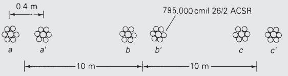
A \(60-\mathrm{Hz}, 100-\) mile, three-phase overhead transmission line, constructed of ACSR conductors, has a series impedance of \((0.1826+j 0.784) \Omega / \mathrm{mi}\) per phase and a shunt capacitive reactance-to-neutral of \(185.5 \times 10^{3}\) \(\angle-90^{\circ} \Omega\)-mi per phase.
Evaluate \(\cosh (\gamma l)\) and \(\tanh (\gamma l / 2)\) for \(\gamma l=0.40 ot 85^{\circ}\) per unit.
A \(500-\mathrm{km}, 500-\mathrm{kV}, 60-\mathrm{Hz}\), uncompensated three-phase line has a positivesequence series impedance \(z=0.03+j 0.35 \Omega / \mathrm{km}\) and a positivesequence shunt admittance \(y=j 4.4 \times 10^{-6} \mathrm{~S} / \mathrm{km}\). Calculate:(a) \(Z_{c}\),(b) \((\gamma
At full load, the line in Problem 5.14 delivers 900 MW at unity power factor and at \(475 \mathrm{kV}\). Calculate:(a) the sending-end voltage,(b) the sending-end current,(c) the sending-end power factor,(d) the full-load line losses, (e) the percent voltage regulation.Problem 5.14A
The \(500-\mathrm{kV}, 60-\mathrm{Hz}\), three-phase line in Problems 4.20 and 4.41 has a 300-km length. Calculate:(a) \(Z_{c}\),(b) \((\gamma l)\), (c) the exact \(A B C D\) parameters for this line. Assume a \(50^{\circ} \mathrm{C}\) conductor temperature.Problem 4.20Calculate the inductive
At full load, the line in Problem 5.16 delivers \(1500 \mathrm{MVA}\) at \(480 \mathrm{kV}\) to the receiving-end load. Calculate the sending-end voltage and percent voltage regulation when the receiving-end power factor is(a) 0.9 lagging,(b) unity, (c) 0.9 leading. Problem 5.16The
A \(60-\mathrm{Hz}, 230-\) mile, three-phase overhead transmission line has a series impedance \(z=0.8431 \angle 79.04^{\circ} \Omega / \mathrm{mi}\) and a shunt admittance \(\gamma=5.105 \times\) \(10^{-6} / 90^{\circ} \mathrm{S} / \mathrm{mi}\). The load at the receiving end is \(125
Using per-unit calculations, rework Problem 5.18 to determine the sending-end voltage and current.Problem 5.18A \(60-\mathrm{Hz}, 230-\) mile, three-phase overhead transmission line has a series impedance \(z=0.8431 \angle 79.04^{\circ} \Omega / \mathrm{mi}\) and a shunt admittance \(\gamma=5.105
(a) The series expansions of the hyperbolic functions are given by\[\begin{aligned}& \cosh \theta=1+\frac{\theta^{2}}{2}+\frac{\theta^{4}}{24}+\frac{\theta^{6}}{720}+\cdots \\& \sinh \theta=1+\frac{\theta^{2}}{6}+\frac{\theta^{4}}{120}+\frac{\theta^{6}}{5040}+\cdots\end{aligned}\]For the
Show that\[A=\frac{V_{\mathrm{S}} I_{\mathrm{S}}+V_{\mathrm{R}} I_{\mathrm{R}}}{V_{\mathrm{R}} I_{\mathrm{S}}+V_{\mathrm{S}} I_{\mathrm{R}}} \quad \text { and } \quad B=\frac{V_{\mathrm{S}}^{2}-V_{\mathrm{R}}^{2}}{V_{\mathrm{R}} I_{\mathrm{S}}+V_{\mathrm{S}} I_{\mathrm{R}}}\]
Consider the \(A\) parameter of the long line given by \(\cosh \theta\), where \(\theta=\) \(\sqrt{Z Y}\). With \(x=e^{-\theta}=x_{1}+j \mathrm{x}_{2}\) and \(A=\mathrm{A}_{1}+j \mathrm{~A}_{2}\), show that \(x_{1}\) and \(x_{2}\) satisfy the following:\[x_{1}^{2}-x_{2}^{2}-2\left(\mathrm{~A}_{1}
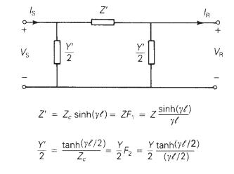
Determine the equivalent \(\pi\) circuit for the line in Problem 5.14 and compare it with the nominal \(\pi\) circuit.Problem 5.14A \(500-\mathrm{km}, 500-\mathrm{kV}, 60-\mathrm{Hz}\), uncompensated three-phase line has a positivesequence series impedance \(z=0.03+j 0.35 \Omega / \mathrm{km}\) and
Determine the equivalent \(\pi\) circuit for the line in Problem 5.16. Compare the equivalent \(\pi\) circuit with the nominal \(\pi\) circuit.Problem 5.16The \(500-\mathrm{kV}, 60-\mathrm{Hz}\), three-phase line in Problems 4.20 and 4.41 has a 300-km length. Calculate:(a) \(Z_{c}\),(b) \((\gamma
Let the transmission line of Problem 5.12 be extended to cover a distance of 200 miles. Assume conditions at the load to be the same as in Problem 5.12. Determine the(a) sending-end voltage,(b) sending-end current,(c) sending-end real and reactive powers, (d) percent voltage regulation.Problem
A 350−km,500−kV,60−Hz350−km,500−kV,60−Hz, three-phase uncompensated line has a positivesequence series reactance x=0.34Ω/kmx=0.34Ω/km and a positive-sequence shunt admittance y=j4.5×10−6 S/kmy=j4.5×10−6 S/km. Neglecting losses, calculate:(a) ZcZc,(b) γlγl,(c) the ABCDABCD
Determine the equivalent ππ circuit for the line in Problem 5.26.Problem 5.26A 350−km,500−kV,60−Hz350−km,500−kV,60−Hz, three-phase uncompensated line has a positivesequence series reactance x=0.34Ω/kmx=0.34Ω/km and a positive-sequence shunt admittance
Rated line voltage is applied to the sending end of the line in Problem 5.26. Calculate the receiving-end voltage when the receiving end is terminated by(a) an open circuit,(b) the surge impedance of the line, and(c) one-half of the surge impedance.(d) Also calculate the theoretical maximum real
Rework Problems 5.9 and 5.16, neglecting the conductor resistance. Compare the results with and without losses.Problem 5.9The \(100-\mathrm{km}, 230-\mathrm{kV}, 60-\mathrm{Hz}\), three-phase line in Problems 4.18 and 4.39 delivers \(300 \mathrm{MVA}\) at \(218 \mathrm{kV}\) to the receiving end at
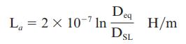
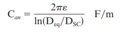
From (4.6.22) and (4.10.4), the series inductance and shunt capacitance of a three-phase overhead line are\[\begin{aligned}\mathrm{L}_{a} & =2 \times 10^{-7} \ln \left(\mathrm{D}_{\mathrm{eq}} / \mathrm{D}_{\mathrm{SL}}ight)=\frac{\mu_{0}}{2 \pi} \ln \left(\mathrm{D}_{\mathrm{eq}} /
A \(500-\mathrm{kV}, 300-\mathrm{km}, 60-\mathrm{Hz}\), three-phase overhead transmission line, assumed to be lossless, has a series inductance of \(0.97 \mathrm{mH} / \mathrm{km}\) per phase and a shunt capacitance of \(0.0115 \mu \mathrm{F} / \mathrm{km}\) per phase. (a) Determine the phase
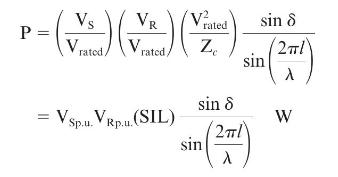
The following parameters are based on a preliminary line design: \(\mathrm{V}_{\mathrm{S}}=\) 1.0 per unit, \(\mathrm{V}_{\mathrm{R}}=0.9\) per unit, \(\lambda=5000 \mathrm{~km}, \mathrm{Z}_{\mathrm{c}}=320 \Omega, \delta=36.8^{\circ}\).A three-phase power of \(700 \mathrm{MW}\) is to be
Consider a long radial line terminated in its characteristic impedance \(Z_{c}\). Determine the following:(a) \(V_{1} / I_{1}\), known as the driving point impedance.(b) \(\left|V_{2}ight| / V_{1} \mid\), known as the voltage gain, in terms of \(\alpha \ell\).(c) \(\left|I_{2}ight| /\left|/
For the case of a lossless line, how would the results of Problem 5.33 change?In terms of ZcZc, which is a real quantity for this case, express P12P12 in terms |I1||I1| and |V1||V1|.Problem 5.33Consider a long radial line terminated in its characteristic impedance \(Z_{c}\). Determine the
For a lossless open-circuited line, express the sending-end voltage, \(V_{1}\), in terms of the receiving-end voltage, \(V_{2}\), for the three cases of short-line model, medium-length line model, and long-line model. Is it true that the voltage at the open receiving end of a long line is higher
For a short transmission line of impedance (R+jX)(R+jX) ohms per phase, show that the maximum power that can be transmitted over the line isPmax=V2RZ2(ZVSVR−R) where Z=√R2+X2Pmax=VR2Z2(ZVSVR−R) where Z=R2+X2when the sending-end and receiving-end voltages are fixed, and for the
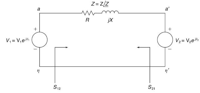
(a) Consider complex power transmission via the three-phase short line for which the per-phase circuit is shown in Figure 5.19. Express \(S_{12}\), the complex power sent by bus 1 (or \(V_{1}\) ), and \(\left(-S_{21}ight.\) ), the complex power received by bus 2 (or \(V_{2}\) ), in terms of
The line in Problem 5.14 has three ACSR \(1113 \mathrm{kcmil}\) conductors per phase. Calculate the theoretical maximum real power that this line can deliver and compare with the thermal limit of the line. Assume \(V_{S}=V_{R}=\) 1.0 per unit and unity power factor at the receiving end.Problem
Repeat Problems 5.14 and 5.38 if the line length is(a) \(200 \mathrm{~km}\) or(b) \(600 \mathrm{~km}\).Problem 5.14A \(500-\mathrm{km}, 500-\mathrm{kV}, 60-\mathrm{Hz}\), uncompensated three-phase line has a positivesequence series impedance \(z=0.03+j 0.35 \Omega / \mathrm{km}\) and a
For the \(500 \mathrm{kV}\) line given in Problem 5.16,(a) calculate the theoretical maximum real power that the line can deliver to the receiving end when rated voltage is applied to both ends;(b) calculate the receiving-end reactive power and power factor at this theoretical loading.Problem
A \(230-\mathrm{kV}, 100-\mathrm{km}, 60-\mathrm{Hz}\), three-phase overhead transmission line with a rated current of \(900 \mathrm{~A} /\) phase has a series impedance \(z=0.088+j 0.465\) \(\Omega / \mathrm{km}\) and a shunt admittance \(y=j 3.524 \mu \mathrm{S} / \mathrm{km}\).(a) Obtain the
A three-phase power of \(460 \mathrm{MW}\) is transmitted to a substation located \(500 \mathrm{~km}\) from the source of power. With \(\mathrm{V}_{\mathrm{S}}=1\) per unit, \(\mathrm{V}_{\mathrm{R}}=0.9\) per unit, \(\lambda=5000 \mathrm{~km}, \mathrm{Z}_{\mathrm{c}}=500 \Omega\), and
Open PowerWorld Simulator case Example 5_4 and graph the load bus voltage as a function of load real power (assuming unity power factor at the load). What is the maximum amount of real power that can be transferred to the load at unity power factor if the load voltage always must be greater than
Repeat Problem 5.43, but now vary the load reactive power, assuming the load real power is fixed at \(1499 \mathrm{MW}\).Problem 5.43Open PowerWorld Simulator case Example 5_4 and graph the load bus voltage as a function of load real power (assuming unity power factor at the load). What is the
For the line in Problems 5.14 and 5.38, determine(a) the practical line loadability in \(\mathrm{MW}\), assuming \(\mathrm{V}_{\mathrm{S}}=1.0\) per unit, \(\mathrm{V}_{\mathrm{R}} \approx 0.95\) per unit, and \(\delta_{\max }=35^{\circ}\); part(b) the full-load current at 0.99 p.f. leading, based
Repeat Problem 5.45 for the \(500 \mathrm{kV}\) line given in Problem 5.10.Problem 5.45For the line in Problems 5.14 and 5.38, determine(a) the practical line loadability in \(\mathrm{MW}\), assuming \(\mathrm{V}_{\mathrm{S}}=1.0\) per unit, \(\mathrm{V}_{\mathrm{R}} \approx 0.95\) per unit, and
Determine the practical line loadability in MW and in per-unit of SIL for the line in Problem 5.14 if the line length is(a) \(200 \mathrm{~km}\) or(b) \(600 \mathrm{~km}\). Assume \(\mathrm{V}_{\mathrm{S}}=1.0\) per unit, \(\mathrm{V}_{\mathrm{R}}=0.95\) per unit, \(\delta_{\max }=35^{\circ}\), and
It is desired to transmit \(2000 \mathrm{MW}\) from a power plant to a load center located \(300 \mathrm{~km}\) from the plant. Determine the number of \(60 \mathrm{~Hz}\), threephase, uncompensated transmission lines required to transmit this power with one line out of service for the following
Repeat Problem 5.48 if it is desired to transmit:(a) 3200 MW to a load center located \(300 \mathrm{~km}\) from the plant or(b) \(2000 \mathrm{MW}\) to a load center located \(400 \mathrm{~km}\) from the plant.Problem 5.48It is desired to transmit \(2000 \mathrm{MW}\) from a power plant to a load
A three-phase power of \(4000 \mathrm{MW}\) is to be transmitted through four identical \(60-\mathrm{Hz}\) overhead transmission lines over a distance of \(300 \mathrm{~km}\). Based on a preliminary design, the phase constant and surge impedance of the line are \(\beta=9.46 \times 10^{-4}
The power flow at any point on a transmission line can be calculated in terms of the \(A B C D\) parameters. By letting \(A=|\mathrm{A}| \angle \alpha, B=|B|\left\langle\beta, \mathrm{V}_{\mathrm{R}}=ight.\) \(\left|\mathrm{V}_{\mathrm{R}}ight| / 0^{\circ}\), and
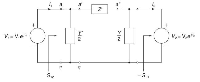
(a) Consider complex power transmission via the three-phase long line for which the per-phase circuit is shown in Figure 5.20. See Problem 5.37 in which the short-line case was considered. Show that\[\begin{aligned}& \text { sending-end power }=S_{12}=\frac{Y^{*}}{2}
Open PowerWorld Simulator case Example 5_8. If the load bus voltage is greater than or equal to \(730 \mathrm{kV}\) even with any line segment out of service, what is the maximum amount of real power that can be delivered to the load?Example 5_8Can five instead of six \(765 \mathrm{kV}\) lines
Repeat Problem 5.53, but now assume any two line segments may be out of service.Problem 5.53Open PowerWorld Simulator case Example 5_8. If the load bus voltage is greater than or equal to 730kV730kV even with any line segment out of service, what is the maximum amount of real power that can be
Recalculate the percent voltage regulation in Problem 5.15 when identical shunt reactors are installed at both ends of the line during light loads, providing \(65 \%\) total shunt compensation. The reactors are removed at full load. Also calculate the impedance of each shunt reactor.Problem 5.15At
Rework Problem 5.17 when identical shunt reactors are installed at both ends of the line, providing \(50 \%\) total shunt compensation. The reactors are removed at full load.Problem 5.17At full load, the line in Problem 5.16 delivers \(1500 \mathrm{MVA}\) at \(480 \mathrm{kV}\) to the receiving-end
Identical series capacitors are installed at both ends of the line in Problem 5.14, providing \(40 \%\) total series compensation. Determine the equivalent \(A B C D\) parameters of this compensated line. Also calculate the impedance of each series capacitor.Problem 5.14A \(500-\mathrm{km},
Identical series capacitors are installed at both ends of the line in Problem 5.16, providing 30\% total series compensation.(a) Determine the equivalent \(A B C D\) parameters for this compensated line.(b) Determine the theoretical maximum real power that this series-compensated line can deliver
Determine the theoretical maximum real power that the seriescompensated line in Problem 5.57 can deliver when \(V_{S}=V_{R}=1.0\) per unit. Problem 5.57Identical series capacitors are installed at both ends of the line in Problem 5.14, providing \(40 \%\) total series compensation. Determine the
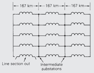
What is the minimum amount of series capacitive compensation \(N_{\mathrm{C}}\) in percent of the positive-sequence line reactance needed to reduce the number of \(765-\mathrm{kV}\) lines in Example 5.8 from five to four? Assume two intermediate substations with one line section out of service.
Determine the equivalent \(A B C D\) parameters for the line in Problem 5.14 if it has \(70 \%\) shunt reactive (inductors) compensation and \(40 \%\) series capacitive compensation. Half of this compensation is installed at each end of the line, as in Figure 5.14.Problem 5.14A \(500-\mathrm{km},
Consider the transmission line of Problem 5.18. (a) Find the \(A B C D\) parameters of the line when uncompensated. (b) For a series capacitive compensation of \(70 \%(35 \%\) at the sending end and \(35 \%\) at the receiving end), determine the \(A B C D\) parameters. Comment on the relative
Given the uncompensated line of Problem 5.18, let a three-phase shunt reactor (inductor) that compensates for \(70 \%\) of the total shunt admittance of the line be connected at the receiving end of the line during no-load conditions. Determine the effect of voltage regulation with the reactor
Let the three-phase lossless transmission line of Problem 5.31 supply a load of 1000 MVA at 0.8 power factor lagging and at \(500 \mathrm{kV}\).(a) Determine the capacitance/phase and total three-phase Mvars supplied by a three-phase, \(\Delta\)-connected shunt-capacitor bank at the receiving end
Open PowerWorld Simulator case Example 5_10 with the series capacitive compensation at both ends of the line in service. Graph the load bus voltage as a function of load real power (assuming unity power factor at the load). What is the maximum amount of real power that can be transferred to the
Open PowerWorld Simulator case Example 5_10 with the series capacitive compensation at both ends of the line in service. With the reactive power load fixed at 400 Mvar, graph the load bus voltage as the MW load is varied between 0 and \(2600 \mathrm{MW}\) in \(200 \mathrm{MW}\) increments. Then
Transform the following sinusoids into phasor form and draw a phasor diagram. Use the additive property of phasors to find \(v_{1}(t)+v_{2}(t)\).(a) \(v_{1}(t)=240 \cos (\omega t+43) \mathrm{V}\)(b) \(v_{2}(t)=120 \cos \left(\omega t-225^{\circ}ight) \mathrm{V}\)
Transform the following sinusoids into phasor form and draw a phasor diagram. Use the additive property of phasors to find \(i_{1}(t)+i_{2}(t)\).(a) \(i_{1}(t)=-10 \sin (\omega t) \mathrm{mA}\)(b) \(i_{2}(t)=6 \cos (\omega t) \mathrm{mA}\)
Transform the following sinusoids into phasor form and draw a phasor diagram. Use the additive property of phasors to find \(v_{1}(t)+v_{2}(t)+v_{3}(t)\).(a) \(v_{1}(t)=480 \cos \left(\omega t-45^{\circ}ight) \mathrm{V}\)(b) \(v_{2}(t)=480 \cos \left(\omega t+73^{\circ}ight) \mathrm{V}\)(c)
Figure P8-4 shows two phasor diagrams.(a) Add the voltage phasors into a new phasor \(\mathbf{V}_{3}\). Draw the sum of this new phasor on a phasor diagram.(b) Add the current phasors into a new phasor \(\mathbf{I}_{3}\). Write the sum of the new current phasor in the time domain if the frequency
Convert the following phasors into sinusoidal waveforms.(a) \(\mathbf{V}_{1}=220 e^{-j 45^{\circ}} \mathrm{V}, \omega=314.2 \mathrm{rad} / \mathrm{s}\)(b) \(\mathbf{V}_{2}=440 e^{-j 225^{\circ}} \mathrm{kV}, \omega=377 \mathrm{rad} / \mathrm{s}\)(c) \(\mathbf{I}_{1}=4 e^{-j 15^{\circ}} \mathrm{A},
Use the phasors below and the additive property to find the sinusoidal waveforms \(v_{3}(t)=v_{1}(t)-v_{2}(t)\) and \(i_{3}(t)=2 i\) \({ }_{1}(t)+3 i_{2}(t)\).\[\begin{aligned}& \mathbf{V}_{1}=15 \angle 15^{\circ} \mathrm{V}, \omega=2 \pi \times 440 \mathrm{rad} / \mathrm{s} \\& \mathbf{V}_{2}=15
Convert the following phasors into sinusoidal waveforms.(a) \(\mathbf{V}_{1}=5+j 5 \mathrm{~V}, \omega=10 \mathrm{krad} / \mathrm{s}\)(b) \(\mathbf{V}_{2}=2 j(5+j 5) \mathrm{V}, \omega=200 \mathrm{rad} / \mathrm{s}\)(c) \(\mathbf{I}_{1}=20-j 20-\) Image \(\mathrm{mA}, \omega=314.2 \mathrm{rad} /
Thinking about the derivative property of phasors as multiplication of the phasor by \(j \omega\), the integral property of phasors should be the inverse operation. Verify that the integration property of phasors is division of the phasor by \(j \omega\).(a) Classically integrate the following
Given the sinusoids \(i_{1}(t)=250 \cos \left(\omega t-60^{\circ}ight)\) \(\mathrm{mA}\) and \(i_{2}(t)=750 \sin (\omega t) \mathrm{mA}\) use the additive property of phasors to find \(i_{3}(t)\) such that \(i_{1}(t)-i_{2}(t)+i_{3}(t)=0\).
Given a sinusoid \(v_{1}(t)\) whose phasor is \(\mathbf{V}_{\mathbf{1}}=4-j 3 \mathrm{~V}\) and its frequency is \(10 \mathrm{rad} / \mathrm{s}\), use phasor methods to find a voltage \(v_{2}(t)\) that equals \(20 d v_{1}(t) / d t-5 v_{1}(t)\).
A design engineer needs to know what value of \(R, L\), or \(C\) to use in circuits to achieve a certain impedance.(a) At what radian frequency will a \(0.015-\mu \mathrm{F}\) capacitor's impedance equal \(-j 20 \Omega\) ?(b) At what radian frequency will a \(33-\mathrm{mH}\) inductor's impedance
For the circuit of Figure P8-13}(a) Find the equivalent impedance \(Z\) when \(\omega=2000 \mathrm{rad} / \mathrm{s}\). Express the result in both polar and rectangular forms.(b) Select standard values from Appendix G to realize the results \(\pm 10 \%\) from part (a).
A certain \(R L C\) series load has a load impedance of \(Z=1000-j 998 \Omega\) when excited by a \(1-\mathrm{krad} / \mathrm{s}\) source and a \(Z=1000-j 80 \Omega\) when driven by a \(10-\mathrm{krad} / \mathrm{s}\) source. Find the values of \(R, L\), and \(C\).
The circuit in Figure P8-17 is operating in the sinusoidal steady state with \(\omega=10 \mathrm{krad} / \mathrm{s}\).(a) What is the equivalent impedance of the circuit?(b) If one wanted to cancel the effect of the reactance, that is, place the circuit in resonance, what element would one place in
The circuit in Figure P8-18 is operating in the sinusoidal steady state with \(\omega=100 \mathrm{krad} / \mathrm{s}\).(a) Find the equivalent impedance \(Z\).(b) What circuit element can be added in series with the equivalent impedance to place the circuit in resonance?(c) Using the equivalent
The circuit of Figure P8-19 is operating at \(50 \mathrm{~Hz}\). Find the equivalent impedance \(Z\).
A capacitor \(C\) is connected in parallel with a resistor \(R\). Select values of \(R\) and \(C\) so that the equivalent impedance of the parallel combination is \(600-j 800 \Omega\) at \(\omega=1\) \(\mathrm{Mrad} / \mathrm{s}\).
Two impedances \(Z_{1}=100-j 50 \Omega\) and \(Z_{2}=500+j 100\) \(\Omega\) are connected in parallel. Find the equivalent impedance of the pair.
A voltage source \(\mathrm{V}_{\mathrm{S}}=100 \angle 90^{\circ} \mathrm{V}\) is connected in series to a resistor of \(10 \Omega\) and an inductor of \(j 10 \Omega\). Find the phasor current \(\mathbf{I}_{\mathrm{S}}\) through the circuit. Draw a phasor diagram of the voltage source and the
(a) Convert the circuit in Figure P8-25 into the phasor domain.(b) Find the phasor current flowing through the circuit and the phasor voltages across the capacitor and the resistor.(c) Plot all three phasors from (b) on a phasor diagram. Describe if the current leads or lags the capacitor voltage.A
A complex load is driven by a current source \(i(t)\) \(=10 \cos (2 \mathrm{k} t) \mathrm{mA}\). The voltage measured across the load is \(v(t\) )\(=100 \cos \left(2 \mathrm{k} t-85^{\circ}ight) \mathrm{V}\). Find the impedance of the load and determine what two elements \(\mathrm{R}, L\), and/or
A current source delivering \(i(t)=120 \cos (500 t) \mathrm{mA}\) is connected across a parallel combination of a \(10-k \Omega\) resistor and a \(0.2-\mu \mathrm{F}\) capacitor. Find the steady-state current \(i_{\mathrm{R}}(t)\) through the resistor and the steady-state current
A practical voltage source can be modeled using an ideal voltage source \(v_{\mathrm{S}}(t)=120 \cos (2000 t) \mathrm{V}\) in series with a5o- \(\Omega\) resistor. Convert the source into the phasor domain and then do a source transformation into a current source in parallel with an impedance.
A circuit consisting of a resistor, capacitor, and inductor is driven by a sinusoidal voltage source \(\mathbf{V}_{S}\) with a 1 \(\mathrm{krad} / \mathrm{s}\) frequency. A phasor diagram of the source and the individual current through each element is shown in Figure P831 . Find the impedance of
Use the unit-output method to find \(\mathbf{V}_{\mathrm{X}}\) and \(\mathbf{I}_{\mathrm{X}}\) in the circuit of Figure P8-34.
An \(R C\) series circuit is excited by a sinusoidal source \(v(t)=V_{\mathrm{A}} \cos (\omega t+\phi) \mathrm{V}\). Determine the effects on the magnitudes of the current, voltages, and impedances caused by changes in the source parameters. Complete the following table. A few cells have been
The OP AMP circuit of Figure P8-41 has \(\mathbf{V}_{\mathrm{S}}=2 \angle-15^{\circ} \mathrm{V}, Z_{\mathrm{S}}=50 \angle+30^{\circ} \Omega, Z_{\mathrm{F}}=100 \angle-45^{\circ} \Omega\), and a \(V_{\mathrm{CC}}\) of \(\pm 15 \mathrm{~V}\).(a) Find the output voltage \(\mathbf{V}_{\mathrm{O}}\)
Design an equivalent \(Z_{\mathrm{S}}=50 \angle+30 \Omega, Z_{\mathrm{F}}=100\) \(\angle-45^{\circ} \Omega\), and \(Z_{\mathrm{L}}=500 \angle-90^{\circ} \Omega\), if the circuit of Figure P8-41 is operating in the steady state at a frequency of \(1000 \mathrm{rad} / \mathrm{s}\). Simulate the
A load of \(Z_{\mathrm{L}}=1000+j 1000 \Omega\) is to be driven by a phasor source \(\mathbf{V}_{\mathrm{S}}=150 \angle 0^{\circ} \mathrm{V}\). The voltage across the load needs to be \(\mathbf{V}_{\mathrm{L}}=100 \angle 0^{\circ} \mathrm{V}\). Design an interface that will meet these conditions.
Design an interface voltage \(v_{\mathrm{S}}(t)=100 \cos \left(2 \times 10^{4} tight) \mathrm{V}\) delivers a steady-state output current of \(i_{\mathrm{O}}(t)=10 \cos \left(2 \times 10^{4} t-60^{\circ}ight) \mathrm{mA}\) to a \(1-\mathrm{k} \Omega\) resistive load. Validate your answer using
Use MATLAB and mesh-current analysis to find the branch currents \(\mathbf{I}_{1}, \mathbf{I}_{2}\), and \(\mathbf{I}_{3}\) in Figure P8-52.
Use mesh-current analysis to find the phasor branch currents \(\mathbf{I}_{1}, \mathbf{I}_{2}\), and \(\mathbf{I}_{3}\) in the circuit shown in Figure P8-53. Validate your answer using Multisim.
Use MATLAB and mesh-current analysis to find the phasor currents \(\mathbf{I}_{\mathrm{A}}\) and \(\mathbf{I}_{\mathrm{B}}\) in Figure P8-55 .
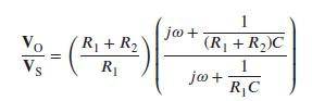
The OP AMP circuit in Figure P8-56 is operating in the sinusoidal steady state.(a) Show that Image(b) Find the value of the magnitude of \(\mathbf{V}_{\mathrm{O}} / \mathbf{V}_{\mathrm{S}}\) at \(\omega=0\) and as \(\omega ightarrow \infty\). At the two frequency extremes, what typical OP AMP
The circuit in Figure P8-57 is operating in the sinusoidal steady state.(a) If \(v_{\mathrm{S}}(t)=1 \cos (2128 t) \mathrm{V}\), find the output \(v_{\mathrm{O}}(t)\).(b) At what frequency is the magnitude of the output voltage equal to half of the magnitude of the input voltage in the circuit of
For the circuit in Figure P8-5 phasor branch currents as follows:(a) Write a set of mesh-current equations. You can reduce the number of mesh equations by doing a source transformation with the current source and inductor.(b) Write the equations in standard form and arrange them in an appropriate
The circuit in Figure P8-60 is operating with \(\omega=20\) \(\mathrm{krad} / \mathrm{s}\).(a) Find the phasor outputs \(\mathbf{V}_{\mathrm{O}}\) and \(\mathbf{I}_{\mathrm{O}}\) in Figure P8-60 when \(\mu=50\) and the phasor input is \(\mathbf{I}_{\mathrm{S}}=1+j 1 \mathrm{~mA}\).(b) Use Multisim
For the circuit of Figure P8-61 find the Thévenin equivalent circuit seen at the output.
The two competing OP AMP circuits in Figure P8-62 are operating in the sinusoidal steady state with \(\omega=100\) \(\mathrm{krad} / \mathrm{s}\). The two manufacturers both claim that their circuit meets the following specifications:Voltage gain at \(100 \mathrm{krad} / \mathrm{s}\) must be 1.414
Find the phasor gain \(K=V_{\mathrm{O}} / \mathrm{V}_{\mathrm{S}}\) and input impedance Z IN of the circuit in Figure P8-64.
A load consisting of a 3.3-k \(\mathrm{k}\) resistor in series with a 3.3\(\mu \mathrm{F}\) capacitor is connected across a voltage source \(v_{\mathrm{S}}(t)=339.4\) \(\cos (314.2 t)\) V. Find the phasor voltage, current, and average power delivered to the load.
Showing 3900 - 4000
of 5433
First
33
34
35
36
37
38
39
40
41
42
43
44
45
46
47
Last
Step by Step Answers