New Semester
Started
Get
50% OFF
Study Help!
--h --m --s
Claim Now
Question Answers
Textbooks
Find textbooks, questions and answers
Oops, something went wrong!
Change your search query and then try again
S
Books
FREE
Study Help
Expert Questions
Accounting
General Management
Mathematics
Finance
Organizational Behaviour
Law
Physics
Operating System
Management Leadership
Sociology
Programming
Marketing
Database
Computer Network
Economics
Textbooks Solutions
Accounting
Managerial Accounting
Management Leadership
Cost Accounting
Statistics
Business Law
Corporate Finance
Finance
Economics
Auditing
Tutors
Online Tutors
Find a Tutor
Hire a Tutor
Become a Tutor
AI Tutor
AI Study Planner
NEW
Sell Books
Search
Search
Sign In
Register
study help
computer science
systems analysis design
Power System Analysis And Design 6th Edition J. Duncan Glover, Thomas Overbye, Mulukutla S. Sarma - Solutions
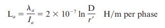
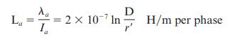
For a completely transposed three-phase line identical conductors, each with GMR denoted \(\mathrm{D}_{\mathrm{S}}\) with conductor distance \(\mathrm{D}_{12}, \mathrm{D}_{23}\), and \(\mathrm{D}_{31}\) give expressions for GMD between phases and the average per-phase inductance.
For EHV lines, a common practice of conductor bundling is used. Why?
Does bundling reduce the series reactance of the line?(a) Yes(b) No
Does \(r^{\prime}=e^{-\frac{1}{4}} r=0.788 r\), which comes in calculation of inductance, play a role in capacitance computations?(a) Yes(b) No
In terms of line-to-line capacitance, the line-to-neutral capacitance of a single-phase transmission line is(a) Same(b) Twice(c) One-half
For either single-phase two-wire line or balanced three-phase three-wire line with equal phase spacing \(D\) and with conductor radius \(r\), the capacitance (line-to-neutral) in \(\mathrm{F} / \mathrm{m}\) is given by \(\mathrm{C}_{\mathrm{an}}=\)
In deriving expressions for capacitance for a balanced three-phase threewire line with equal phase spacing, the following relationships may have been used.(i) Sum of positive-sequence charges, \(q_{a}+q_{b}+q_{c}=0\)(ii) The sum of the two line-to-line voltages \(V_{a b}+V_{a c}\) is equal to
When calculating line capacitance, it is normal practice to replace a stranded conductor by a perfectly conducting solid cylindrical conductor whose radius equals the out side radius of the stranded conductor.(a) True(b) False
For bundled-conductor configurations, the expressions for calculating \(\mathrm{D}_{\mathrm{SL}}\) in inductance calculations and \(\mathrm{D}_{\mathrm{SC}}\) in capacitance calculations are analogous, except that the conductor outside radius \(r\) replaces the conductor GMR,
The current supplied to the transmission-line capacitance is called
For a completely transposed three-phase line that has balanced positivesequence voltages, the total reactive power supplied by the three-phase line, in var, is given by \(\mathrm{Q}_{\mathrm{C} 3}=\) in terms of frequency \(\omega\), line-to-neutral capacitance \(\mathrm{C}_{\mathrm{an}}\), and
Considering lines with neutral conductors and earth return, the effect of earth plane is accounted for by the method of conducting earth plane. with a perfectly
The affect of the earth plane is to slightly increase the capacitance, and as the line height increases, the effect of earth becomes negligible.(a) True(b) False
When the electric field strength at a conductor surface exceeds the breakdown strength of air, current discharges occur. This phenomenon is called
To control corona, transmission lines are usually designed to maintain the calculated conductor surface electric field strength below \(\mathrm{kV}_{\mathrm{rms}} / \mathrm{cm}\).
Along with limiting corona and its effects, particularly for EHV lines, the maximum ground-level electric field strength needs to be controlled to avoid the shock hazard.(a) True(b) False
Considering two parallel three-phase circuits that are close together, when calculating the equivalent series-impedance and shunt-admittance matrices, mutual inductive and capacitive couplings between the two circuits can be neglected.(a) True(b) False
The Aluminum Electrical Conductor Handbook lists a dc resistance of \(0.01558 \mathrm{ohm}\) per \(1000 \mathrm{ft}\) at \(20^{\circ} \mathrm{C}\) and a \(60-\mathrm{Hz}\) resistance of \(0.0956 \mathrm{ohm}\) per mile at \(50^{\circ} \mathrm{C}\) for the all-aluminum Marigold conductor, which has
The temperature dependence of resistance is also quantified by the relation \(\mathrm{R}_{2}=\mathrm{R}_{1}\left[1+\alpha\left(\mathrm{T}_{2}-\mathrm{T}_{1}ight)ight]\) where \(\mathrm{R}_{1}\) and \(\mathrm{R}_{2}\) are the resistances at temperatures \(T_{1}\) and \(T_{2}\), respectively, and
A transmission-line cable with a length of \(2 \mathrm{~km}\) consists of 19 strands of identical copper conductors, each \(1.5 \mathrm{~mm}\) in diameter. Because of the twist of the strands, the actual length of each conductor is increased by \(5 \%\). Determine the resistance of the cable if the
One thousand circular mils or \(1 \mathrm{kcmil}\) is sometimes designated by the abbreviation MCM. Data for commercial bare-aluminum electrical conductors lists a \(60 \mathrm{~Hz}\) resistance of \(0.0080 \mathrm{ohm}\) per kilometer at \(75^{\circ} \mathrm{C}\) for a 793-MCM AAC conductor.(a)
A \(60-\mathrm{Hz}, 765-\mathrm{kV}\), three-phase overhead transmission line has four ACSR \(900 \mathrm{kcmil} 54 / 3\) conductors per phase. Determine the \(60 \mathrm{~Hz}\) resistance of this line in ohms per kilometer per phase at \(50^{\circ} \mathrm{C}\).
A three-phase overhead transmission line is designed to deliver 190.5 MVA at \(220 \mathrm{kV}\) over a distance of \(63 \mathrm{~km}\), such that the total transmission line loss is not to exceed \(2.5 \%\) of the rated line MVA. Given the resistivity of the conductor material to be \(2.84 \times
If the per-phase line loss in a 70-km-long transmission line is not to exceed \(65 \mathrm{~kW}\) while it is delivering 100 A per phase, compute the required conductor diameter if the resistivity of the conductor material is \(1.72 \times 10^{-8} \Omega-\mathrm{m}\).
A 60-Hz, single-phase two-wire overhead line has solid cylindrical copper conductors with a \(1.5 \mathrm{~cm}\) diameter. The conductors are arranged in a horizontal configuration with \(0.5 \mathrm{~m}\) spacing. Calculate in \(\mathrm{mH} / \mathrm{km}\) (a) the inductance of each conductor due
Rework Problem 4.8 if the diameter of each conductor is(a) increased by \(20 \%\) to \(1.8 \mathrm{~cm}\) or(b) decreased by \(20 \%\) to \(1.2 \mathrm{~cm}\) without changing the phase spacing. Compare the results with those of Problem 4.8.Problem 4.8A 60-Hz, single-phase two-wire overhead line
A \(60-\mathrm{Hz}\), three-phase three-wire overhead line has solid cylindrical conductors arranged in the form of an equilateral triangle with 4-ft conductor spacing. The conductor diameter is \(0.5 \mathrm{in}\). Calculate the positive-sequence inductance in \(\mathrm{H} / \mathrm{m}\) and the
Rework Problem 4.10 if the phase spacing is (a) increased by \(20 \%\) to \(4.8 \mathrm{ft}\) or (b) decreased by \(20 \%\) to \(3.2 \mathrm{ft}\). Compare the results with those of Problem 4.10.Problem 4.10A \(60-\mathrm{Hz}\), three-phase three-wire overhead line has solid cylindrical conductors
Find the inductive reactance per mile of a single-phase overhead transmission line operating at \(60 \mathrm{~Hz}\) given the conductors to be Partridge and the spacing between centers to be \(30 \mathrm{ft}\).
A single-phase overhead transmission line consists of two solid aluminum conductors having a radius of \(3 \mathrm{~cm}\) with a spacing \(3.5 \mathrm{~m}\) between centers. (a) Determine the total line inductance in \(\mathrm{mH} / \mathrm{m}\). (b) Given the operating frequency to be \(60
(a) In practice, one deals with the inductive reactance of the line per phase per mile and use the logarithm to the base 10. Show that Eq. (4.5.9) of the text can be rewritten as\[\begin{aligned}x & =k \log \frac{\mathrm{D}}{r^{\prime}} \text { ohms per mile per phase } \\&
Find the GMR of a stranded conductor consisting of six outer strands surrounding and touching one central strand, all strands having the same radius \(r\).
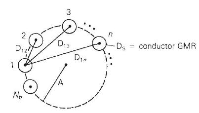
A bundle configuration for UHV lines (above \(1000 \mathrm{kV}\) ) has identical conductors equally spaced around a circle, as shown in Figure 4.29. \(N_{b}\) is the number of conductors in the bundle, \(A\) is the circle radius, and \(D_{S}\) is the conductor GMR. Using the distance
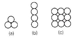
Determine the GMR of each of the unconventional stranded conductors shown in Figure 4.30. All strands have the same radius \(r\). (a) o (b) (c)
A \(230-\mathrm{kV}, 60-\mathrm{Hz}\), three-phase completely transposed overhead line has one ACSR \(954 \mathrm{kcmil}\) conductor per phase and flat horizontal phase spacing, with \(7 \mathrm{~m}\) between adjacent conductors. Determine the inductance in \(\mathrm{H} / \mathrm{m}\) and the
Rework Problem 4.18 if the phase spacing between adjacent conductors is (a) increased by \(10 \%\) to \(7.7 \mathrm{~m}\) or (b) decreased by \(10 \%\) to \(6.3 \mathrm{~m}\). Compare the results with those of Problem 4.18.Problem 4.18A \(230-\mathrm{kV}, 60-\mathrm{Hz}\), three-phase completely
Calculate the inductive reactance in \(\Omega / \mathrm{km}\) of a bundled \(500-\mathrm{kV}, 60-\mathrm{Hz}\), three-phase completely transposed overhead line having three ACSR \(1113 \mathrm{kcmil}\) conductors per bundle, with \(0.5 \mathrm{~m}\) between conductors in the bundle. The horizontal
Rework Problem 4.20 if the bundled line has (a) three ACSR, \(1351 \mathrm{kcmil}\) conductors per phase or (b) three ACSR, \(900 \mathrm{kcmil}\) conductors per phase, without changing the bundle spacing or the phase spacings between bundle centers. Compare the results with those of Problem
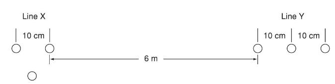
The conductor configuration of a bundled single-phase overhead transmission line is shown in Figure 4.31. Line \(\mathrm{X}\) has its three conductors situated at the corners of an equilateral triangle with \(10 \mathrm{~cm}\) spacing. Line \(\mathrm{Y}\) has its three conductors arranged in a
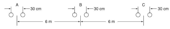
Figure 4.32 shows the conductor configuration of a completely transposed three-phase overhead transmission line with bundled phase conductors. All conductors have a radius of \(0.74 \mathrm{~cm}\) with a \(30-\mathrm{cm}\) bundle spacing. (a) Determine the inductance per phase in \(\mathrm{mH} /
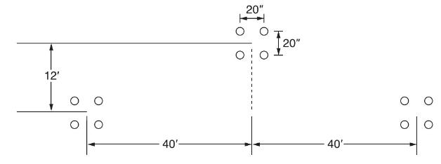
Consider a three-phase overhead line made up of three phase conductors: Linnet, \(336.4 \mathrm{kcmil}\), and ACSR 26/7. The line configuration is such that the horizontal separation between center of \(\mathrm{C}\) and that of \(\mathrm{A}\) is 40", and between that of \(\mathrm{A}\) and
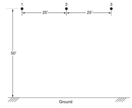
For the overhead line of configuration shown in Figure 4.33 operating at \(60 \mathrm{~Hz}\) and a conductor temperature of \(70^{\circ} \mathrm{C}\), determine the resistance per phase, inductive reactance in ohms/mile/phase, and the currentcarrying capacity of the overhead line. Each conductor is
Consider a symmetrical bundle with \(N\) subconductors arranged in a circle of radius A. The inductance of a single-phase symmetrical bundleconductor line is given by\(\mathrm{L}=2 \times 10^{-7} \ln \frac{\mathrm{GMD}}{\mathrm{GMR}} \mathrm{H} / \mathrm{m}\)Where GMR is given by \(\left[N
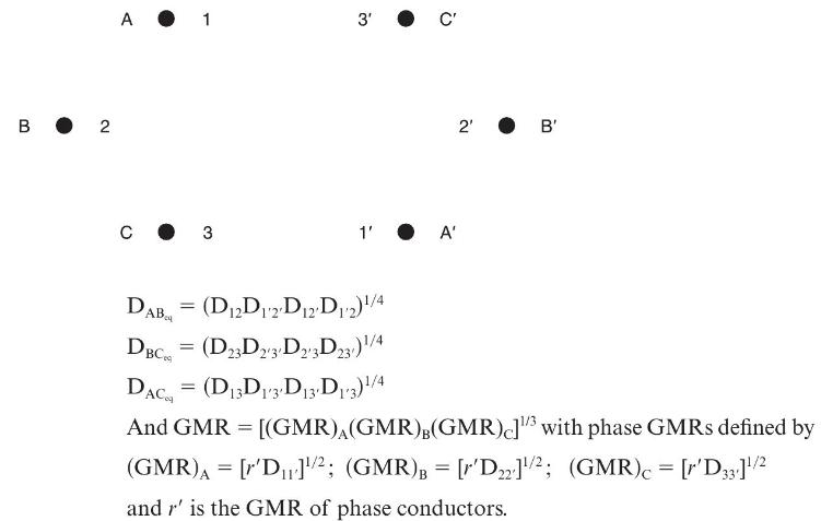
Figure 4.34 shows double-circuit conductors' relative positions in segment 1 of transposition of a completely transposed three-phase overhead transmission line. The inductance is given by\(\mathrm{L}=2 \times 10^{-7} \ln \frac{\mathrm{GMD}}{\mathrm{GMR}} \mathrm{H} / \mathrm{m} /\) phase Where GMD
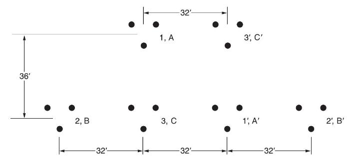
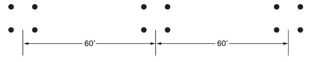
For the case of double-circuit, bundle-conductor lines, the same method indicated in Problem 4.27 applies with \(r^{\prime}\) replaced by the bundle's GMR in the calculation of the overall GMR.Now consider a double-circuit configuration shown in Figure 4.36 that belongs to a \(500-\mathrm{kV}\),
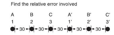
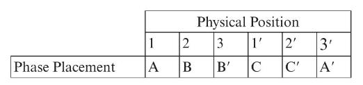
Reconsider Problem 4.28 with an alternate phase placement given below:Calculate the inductive reactance of the line in \(\Omega / \mathrm{mi} /\) phase.Problem 4.28For the case of double-circuit, bundle-conductor lines, the same method indicated in Problem 4.27 applies with \(r^{\prime}\) replaced
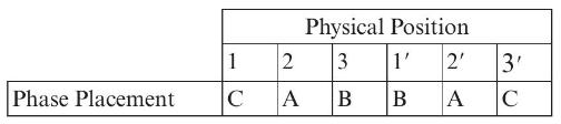
Reconsider Problem 4.28 with still another alternate phase placement shown below.Find the inductive reactance of the line in \(\Omega / \mathrm{mi} /\) phase.Problem 4.28For the case of double-circuit, bundle-conductor lines, the same method indicated in Problem 4.27 applies with \(r^{\prime}\)
Figure 4.37 shows the conductor configuration of a three-phase transmission line and a telephone line supported on the same towers. The power line carries a balanced current of \(250 \mathrm{~A} /\) phase at \(60 \mathrm{~Hz}\), while the telephone line is directly located below phaseb. Assume
Calculate the capacitance-to-neutral in \(\mathrm{F} / \mathrm{m}\) and the admittance-to-neutral in S/km for the single-phase line in Problem 4.8. Neglect the effect of the earth plane.Problem 4.8A 60-Hz, single-phase two-wire overhead line has solid cylindrical copper conductors with a \(1.5
Rework Problem 4.32 if the diameter of each conductor is (a) increased by \(20 \%\) to \(1.8 \mathrm{~cm}\) or (b) decreased by \(20 \%\) to \(1.2 \mathrm{~cm}\). Compare the results with those of Problem 4.32.Problem 4.32Calculate the capacitance-to-neutral in \(\mathrm{F} / \mathrm{m}\) and the
Calculate the capacitance-to-neutral in \(\mathrm{F} / \mathrm{m}\) and the admittance-to-neutral in S/km for the three-phase line in Problem 4.10. Neglect the effect of the earth plane.Problem 4.10A \(60-\mathrm{Hz}\), three-phase three-wire overhead line has solid cylindrical conductors arranged
Rework Problem 4.34 if the phase spacing is (a) increased by \(20 \%\) to \(4.8 \mathrm{ft}\) or (b) decreased by \(20 \%\) to \(3.2 \mathrm{ft}\). Compare the results with those of Problem 4.34.Problem 4.34Calculate the capacitance-to-neutral in \(\mathrm{F} / \mathrm{m}\) and the
The line of Problem 4.23 as shown in Figure 4.32 is operating at \(60 \mathrm{~Hz}\). Determine(a) the line-to-neutral capacitance in \(\mathrm{nF} / \mathrm{km}\) per phase and in \(\mathrm{nF} / \mathrm{mi}\) per phase;(b) the capacitive reactance in \(\Omega-\mathrm{km}\) per phase and in
(a) In practice, one deals with the capacitive reactance of the line in ohms ⋅⋅ mi to neutral. Show that Eq. (4.9.15) of the text can be rewritten asXC=k′logDr ohms ⋅ mi to netural =x′d+x′aXC=k′logDr ohms ⋅ mi to netural =xd′+xa′where x′d=k′logDxd′=k′logD
The capacitance per phase of a balanced three-phase overhead line is given by\[\mathrm{C}=\frac{0.0389}{\log (\mathrm{GMD} / r)} \mu \mathrm{f} / \mathrm{mi} / \text { phase }\]For the line of Problem 4.24, determine the capacitive reactance per phase in \(\Omega \cdot \mathrm{mi}\).Problem
Calculate the capacitance-to-neutral in \(\mathrm{F} / \mathrm{m}\) and the admittance-to-neutral in \(\mathrm{S} / \mathrm{km}\) for the three-phase line in Problem 4.18. Also calculate the linecharging current in \(\mathrm{kA} /\) phase if the line is \(110 \mathrm{~km}\) in length and is
Rework Problem 4.39 if the phase spacing between adjacent conductors is (a) increased by \(10 \%\) to \(7.7 \mathrm{~m}\) or (b) decreased by \(10 \%\) to \(6.3 \mathrm{~m}\). Compare the results with those of Problem 4.39.Problem 4.39Calculate the capacitance-to-neutral in \(\mathrm{F} /
Calculate the capacitance-to-neutral in \(\mathrm{F} / \mathrm{m}\) and the admittance-to-neutral in \(\mathrm{S} / \mathrm{km}\) for the line in Problem 4.20. Also calculate the total reactive power in Mvar/km supplied by the line capacitance when it is operated at \(500 \mathrm{kV}\). Neglect the
Rework Problem 4.41 if the bundled line has (a) three ACSR, 1351-kcmil conductors per phase or (b) three ACSR, \(900 \mathrm{kcmil}\) conductors per phase without changing the bundle spacing or the phase spacings between bundle centers.Problem 4.41Calculate the capacitance-to-neutral in
Three ACSR Drake conductors are used for a three-phase overhead transmission line operating at \(60 \mathrm{~Hz}\). The conductor configuration is in the form of an isosceles triangle with sides of 20, 20, and \(38 \mathrm{ft}\). (a) Find the capacitance-to-neutral and capacitive
Consider the line of Problem 4.25. Calculate the capacitive reactance per phase in \(\Omega \cdot \mathrm{mi}\).Problem 4.25For the overhead line of configuration shown in Figure 4.33 operating at \(60 \mathrm{~Hz}\) and a conductor temperature of \(70^{\circ} \mathrm{C}\), determine the resistance
For an average line height of \(10 \mathrm{~m}\), determine the effect of the earth on capacitance for the single-phase line in Problem 4.32. Assume a perfectly conducting earth plane.Problem 4.32Calculate the capacitance-to-neutral in \(\mathrm{F} / \mathrm{m}\) and the admittance-to-neutral in
A three-phase \(60-\mathrm{Hz}, 125-\mathrm{km}\) overhead transmission line has flat horizontal spacing with three identical conductors. The conductors have an outside diameter of \(3.28 \mathrm{~cm}\) with \(12 \mathrm{~m}\) between adjacent conductors. (a) Determine the capacitive
For the single-phase line of Problem 4.14(b), if the height of the conductor above ground is \(80 \mathrm{ft}\)., determine the line-to-line capacitance in \(\mathrm{F} / \mathrm{m}\). Neglecting earth effect, evaluate the relative error involved. If the phase separation is doubled, repeat the
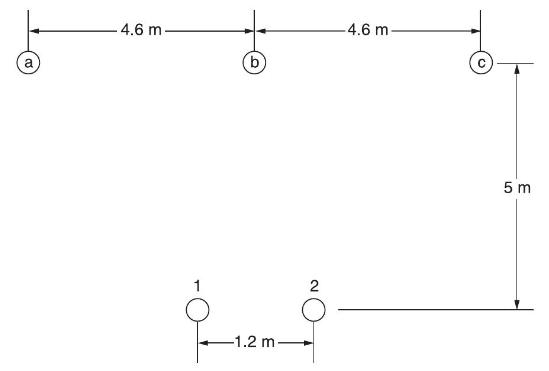
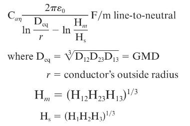
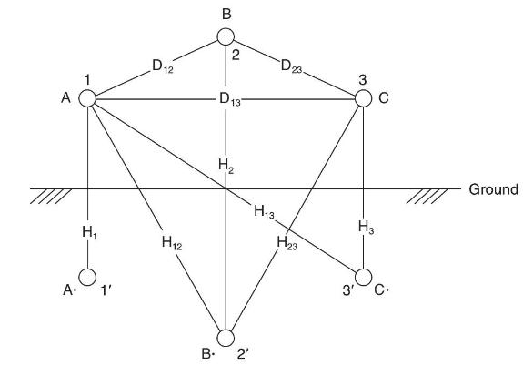
The capacitance of a single-circuit, three-phase transposed line with the configuration shown in Figure 4.38, including ground effect, and with conductors not equilaterally spaced is given by(a) Now consider Figure 4.39 in which the configuration of a three-phase, single circuit,
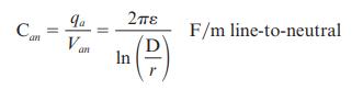
The capacitance-to-neutral, neglecting the ground effect, for the threephase, single-circuit, bundle-conductor line is given by\[\begin{gathered}\mathrm{C}_{a \eta}=\frac{2 \pi \varepsilon_{0}}{\ell \eta\left(\frac{\mathrm{GMD}}{\mathrm{GMR}}ight)} \mathrm{F} / \mathrm{m} \text { line-to-neutral }
Calculate the conductor surface electric field strength in \(\mathrm{kVrms} / \mathrm{cm}\) for the single-phase line in Problem 4.32 when the line is operating at \(20 \mathrm{kV}\). Also calculate the ground-level electric field strength in \(\mathrm{kVrms} / \mathrm{m}\) directly under one
Rework Problem 4.50 if the diameter of each conductor is(a) increased by \(25 \%\) to \(1.875 \mathrm{~cm}\) (b) decreased by \(25 \%\) to \(1.125 \mathrm{~cm}\) without changing the phase spacings. Compare the results with those of Problem 4.50.Problem 4.50Calculate the conductor surface electric
Representing a transmission line by the two-port network, in terms of \(A B C D\) parameters,(a) express \(V_{S}\), which is the sending-end voltage, in terms of \(V_{R}\), which is the receiving-end voltage, and \(I_{R}\), the receiving-end current, and(b) express \(I_{S}\), which is the
As applied to linear, passive, bilateral two-port networks, the \(A B C D\) parameters satisfy \(A D-B C=1\).(a) True(b) False
Express the no-load receiving-end voltage \(V_{\mathrm{RNL}}\) in terms of the sendingend voltage, \(V_{S}\), and the \(A B C D\) parameters.
The \(A B C D\) parameters, which are in general complex numbers, have units of ________, ________, ________, and ________, respectively.
The loadability of short transmission lines (less than \(25 \mathrm{~km}\), represented by including only series resistance and reactance) is determined by ________; that of medium lines (less than \(250 \mathrm{~km}\), represented by nominal \(\pi\) circuit) is determined by ________; and that of
Can the voltage regulation, which is proportional to \(\left(V_{\mathrm{RNL}}-V_{\mathrm{RFL}}\right)\) , be negative?(a) Yes(b) No
The propagation constant, which is a complex quantity in general, has units of ________, and the characteristic impedance has units of ________.
Express hyperbolic functions \(\cosh \sqrt{x}\) and \(\sinh \sqrt{x}\) in terms of exponential functions.
\(e^{\gamma}\), where \(\gamma=\alpha+j \beta\), can be expressed as \(e^{\alpha l} / \beta l\), in which \(\alpha l\) is dimensionless and \(\beta l\) is in radians (also dimensionless).(a) True(b) False
The equivalent \(\pi\) circuit is identical in structure to the nominal \(\pi\) circuit.(a) True(b) False
The correction factors \(F_{1}=\sinh (\gamma l) \gamma l\) and \(F_{2}=\tanh (\gamma l / 2) /(\gamma l / 2)\), which are complex numbers, have the units of ________.
For a lossless line, the surge impedance is purely resistive and the propagation constant is pure imaginary.(a) True(b) False
For equivalent \(\pi\) circuits of lossless lines, the \(A\) and \(D\) parameters are pure ________, whereas \(B\) and \(C\) parameters are pure ________.
In equivalent \(\pi\) circuits of lossless lines, \(Z^{\prime}\) is pure ________, and \(Y^{\prime}\) is pure ________.
Typical power-line lengths are only a small fraction of the \(60-\mathrm{Hz}\) wavelength.(a) True(b) False
The velocity of propagation of voltage and current waves along a lossless overhead line is the same as speed of light.(a) True(b) False
Surge Impedance Loading (SIL) is the power delivered by a lossless line to a load resistance equal to ________.
For a lossless line, at SIL, the voltage profile is ________, and the real power delivered, in terms of rated line voltage \(\mathrm{V}\) and surge impedance \(\mathrm{Z}_{c}\), is given by ________.
The maximum power that a lossless line can deliver, in terms of the voltage magnitudes \(V_{S}\) and \(V_{R}\) (in volts) at the ends of the line held constant, and the series reactance \(\mathrm{X}^{\prime}\) of the corresponding equivalent \(\pi\) circuit, is given by ________, in watts.
The maximum power flow for a lossy line is somewhat less than that for a lossless line.(a) True(b) False
For short lines less than \(25 \mathrm{~km}\) long, loadability is limited by the thermal rating of the conductors or by terminal equipment ratings, not by voltage drop or stability considerations.(a) True(b) False
Increasing the transmission line voltage reduces the required number of lines for the same power transfer.(a) True(b) False
Intermediate substations are often economical from the viewpoint of the number of lines required for power transfer if their costs do not outweigh the reduction in line costs.(a) True(b) False
Shunt reactive compensation improves transmission-line ________, whereas series capacitive compensation increases transmission-line ________.
Static-var-compensators can absorb reactive power during light loads and deliver reactive power during heavy loads.(a) True(b) False
A \(30-\mathrm{km}, 34.5-\mathrm{kV}, 60-\mathrm{Hz}\), three-phase line has a positive-sequence series impedance \(z=0.19+j 0.34 \Omega / \mathrm{km}\). The load at the receiving end absorbs 10 MVA at \(33 \mathrm{kV}\). Assuming a short line, calculate:(a) the \(A B C D\) parameters,(b) the
A \(200-\mathrm{km}, 230-\mathrm{kV}, 60-\mathrm{Hz}\), three-phase line has a positive-sequence series impedance \(z=0.08+j 0.48 \Omega / \mathrm{km}\) and a positive-sequence shunt admittance \(y=j 3.33 \times 10^{-6} \mathrm{~S} / \mathrm{km}\). At full load, the line delivers \(250
Rework Problem 5.2 in per unit using 1000-MVA (three-phase) and \(230-\mathrm{kV}\) (line-to-line) base values. Calculate:(a) the per-unit \(A B C D\) parameters,(b) the per-unit sending-end voltage and current,(c) the percent voltage regulation.Problem 5.2A \(200-\mathrm{km}, 230-\mathrm{kV},
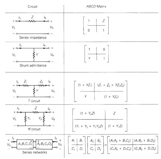
Derive the \(A B C D\) parameters for the two networks in series, as shown in Figure 5.4.Figure 5.4 +0+ +0 Vs + Is Vs Vs Is +0 Series impedance Is Circuit Z Z Y Shunt admittance la Z T circuit Z TT circuit V Series networks + V la - + IR V A,B,C,D A,B,CD IA +1 ABCD Matrix H 1 (1 + YZ) (Z + Z + YZ
Derive the \(A B C D\) parameters for the T circuit shown in Figure 5.4.Figure 5.4 +0+ +0 Vs + Is Vs Vs Is +0 Series impedance Is Circuit Z Z Y Shunt admittance la Z T circuit Z TT circuit V Series networks + V la - + IR V A,B,C,D A,B,CD IA +1 ABCD Matrix H 1 (1 + YZ) (Z + Z + YZ Z) Z K 1 Y (1 +
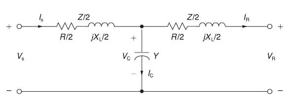
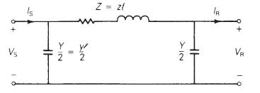
(a) Consider a medium-length transmission line represented by a nominal \(\pi\) circuit shown in Figure 5.3 of the text. Draw a phasor diagram for lagging power-factor condition at the load (receiving end).(b) Now consider a nominal \(\mathrm{T}\) circuit of the medium-length transmission line
The per-phase impedance of a short three-phase transmission line is \(0.5 / 53.15^{\circ} \Omega\). The three-phase load at the receiving end is \(1200 \mathrm{~kW}\) at 0.8 p.f. lagging. If the line-to-line sending-end voltage is \(3.3 \mathrm{kV}\), determine(a) the receiving-end line-to-line
Showing 3800 - 3900
of 5433
First
32
33
34
35
36
37
38
39
40
41
42
43
44
45
46
Last
Step by Step Answers