New Semester
Started
Get
50% OFF
Study Help!
--h --m --s
Claim Now
Question Answers
Textbooks
Find textbooks, questions and answers
Oops, something went wrong!
Change your search query and then try again
S
Books
FREE
Study Help
Expert Questions
Accounting
General Management
Mathematics
Finance
Organizational Behaviour
Law
Physics
Operating System
Management Leadership
Sociology
Programming
Marketing
Database
Computer Network
Economics
Textbooks Solutions
Accounting
Managerial Accounting
Management Leadership
Cost Accounting
Statistics
Business Law
Corporate Finance
Finance
Economics
Auditing
Tutors
Online Tutors
Find a Tutor
Hire a Tutor
Become a Tutor
AI Tutor
AI Study Planner
NEW
Sell Books
Search
Search
Sign In
Register
study help
computer science
systems analysis design
Power System Analysis And Design 6th Edition J. Duncan Glover, Thomas Overbye, Mulukutla S. Sarma - Solutions
Does an open- \(\Delta\) connection permit balanced three-phase operation?(a) Yes(b) No
Does an open- \(\Delta\) operation, the kVA rating compared to that of the original three-phase bank is(a) \(2 / 3\)(b) \(58 \%\)(c) 1
It is stated that(i) balanced three-phase circuits can be solved in per unit on a per-phase basis after converting \(\Delta\)-load impedances to equivalent \(Y\) impedances.(ii) Base values can be selected either on a per-phase basis or on a threephase basis.(a) Both statements are true.(b) Neither
In developing per-unit equivalent circuits for three-phase transformers, under balanced three-phase operation.(i) A common \(\mathrm{S}_{\text {base }}\) is selected for both the \(\mathrm{H}\) and \(\mathrm{X}\) terminals.(ii) The ratio of the voltage bases \(V_{\text {baseH }} / V_{\text {baseX
In per-unit equivalent circuits of practical three-phase transformers, under balanced three-phase operation, in which of the following connections would a phase-shifting transformer come up?(a) \(\mathrm{Y}-\mathrm{Y}\)(b) \(\mathrm{Y}-\Delta\)(c) \(\Delta-\Delta\)
A low value of transformer leakage reactance is desired to minimize the voltage drop, but a high value is desired to limit the fault current, thereby leading to a compromise in the design specification.(a) True(b) False
Consider a single-phase three-winding transformer with the primary excited winding of N1N1 turns carrying a current I1I1 and two secondary windings of N2N2 and N3N3 turns, delivering currents of I2I2 and I3I3 respectively. For an ideal case, how are the ampere-turns balanced? (a)
For developing per-unit equivalent circuits of single-phase three-winding transformer, a common \(\mathrm{S}_{\text {base }}\) is selected for all three windings, and voltage bases are selected in proportion to the rated voltage of the windings.(a) True(b) False
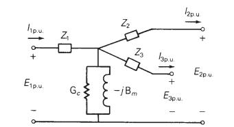
Consider the equivalent circuit of Figure 3.20 (c) in the text. After neglecting the winding resistances and exciting current, could \(X_{1}, X_{2}\), or \(X_{3}\) become negative, even though the leakage reactance are always positive?(a) Yes(b) NoFigure 3.20 (c) hp.u. E1p.u. 1 N Z Ge Z Z3 13pu
Consider an ideal single-phase 2-winding transformer of turns ratio \(N_{1} / N_{2}=a\). If it is converted to an autotransformer arrangement with a transformation ratio of \(V_{H} / V_{X}=1+a\), (the autotransformer rating) two-winding transformer rating) would then be(a) \(1+a\)(b)
For the same output, the autotransformer (with not too large a turns ratio) is smaller in size than a two-winding transformer and has high efficiency as well as superior voltage regulation.(a) True(b) False
The direct electrical connection of the windings allows transient over voltages to pass through the autotransformer more easily, and that is an important disadvantage of the autotransformer.(a) True(b) False
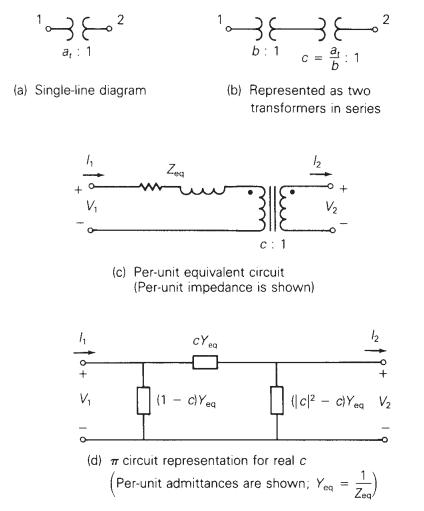
Consider Figure 3.25 of the text for a transformer with off-nominal turns ratio.(i) The per-unit equivalent circuit shown in part (c) contains an ideal transformer which cannot be accommodated by some computer programs.(a) True(b) False(ii) In the \(\pi\)-circuit representation for real
(a) An ideal single-phase two-winding transformer with turns ratio \(a_{t}=\) \(N_{1} / N_{2}\) is connected with a series impedance \(Z_{2}\) across winding 2 . If one wants to replace \(Z_{2}\), with a series impedance \(Z_{1}\) across winding 1 and keep the terminal behavior of the two circuits
An ideal transformer with \(N_{1}=1000\) and \(N_{2}=250\) is connected with an impedance \(Z_{22}\) across winding 2. If \(V_{1}=1000 \angle 0^{\circ} \mathrm{V}\) and \(I_{1}=5 \angle-30^{\circ}\) A, determine \(V_{2}, I_{2}, Z_{2}\), and the impedance \(Z_{2}^{\prime}\), which is the value of
Consider an ideal transformer with \(N_{1}=3000\) and \(N_{2}=1000\) turns. Let winding 1 be connected to a source whose voltage is \(e_{1}(t)=100(1-|t|)\) volts for \(-1 \leq t \leq 1\) and \(e_{1}(t)=0\) for \(|t|>1\) second. A 2 -farad capacitor is connected across winding 2 . Sketch \(e_{1}(t),
A single-phase 100-kVA, 2400/240-volt, 60-Hz distribution transformer is used as a step-down transformer. The load, which is connected to the 240 -volt secondary winding, absorbs \(60 \mathrm{kVA}\) at 0.8 power factor lagging and is at 230 volts. Assuming an ideal transformer, calculate the
Rework Problem 3.4 if the load connected to the \(240-\mathrm{V}\) secondary winding absorbs \(110 \mathrm{kVA}\) under short-term overload conditions at an 0.8 power factor leading and at 230 volts.Problem 3.4A single-phase 100-kVA, 2400/240-volt, 60-Hz distribution transformer is used as a
For a conceptual single-phase phase-shifting transformer, the primary voltage leads the secondary voltage by \(30^{\circ}\). A load connected to the secondary winding absorbs \(110 \mathrm{kVA}\) at an 0.8 power factor leading and at a voltage \(E_{2}=277 / 0^{\circ}\) volts. Determine (a) the
Consider a source of voltage \(v(t)=10 \sqrt{2} \sin (2 t) \mathrm{V}\), with an internal resistance of \(1800 \Omega\). A transformer that can be considered as ideal is used to couple a \(50-\Omega\) resistive load to the source. (a) Determine the transformer primary-to-secondary turns ratio
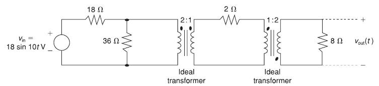
For the circuit shown in Figure 3.31, determine \(v_{\text {out }}(t)\) Vin 18 sin 10t V + 18 36 www 2:1 Ideal transformer w 1:2 Ideal transformer 8 + Vout(t)
A single-phase transformer has 2000 turns on the primary winding and 500 turns on the secondary. Winding resistances are \(R_{1}=2 \Omega\), and \(R_{2}=\) \(0.125 \Omega\); leakage reactances are \(X_{1}=8 \Omega\) and \(X_{2}=0.5 \Omega\). The resistance load on the secondary is \(12 \Omega\).(a)
A single-phase step-down transformer is rated \(13 \mathrm{MVA}, 66 \mathrm{kV} / 11.5 \mathrm{kV}\). With the \(11.5 \mathrm{kV}\) winding short-circuited, rated current flows when the voltage applied to the primary is \(5.5 \mathrm{kV}\). The power input is read as \(100 \mathrm{~kW}\). Determine
For the transformer in Problem 3.10, the open-circuit test with \(11.5 \mathrm{kV}\) applied results in a power input of \(65 \mathrm{~kW}\) and a current of \(30 \mathrm{~A}\). Compute the values for \(G_{c}\) and \(B_{m}\) in siemens referred to the high-voltage winding. Compute the efficiency of
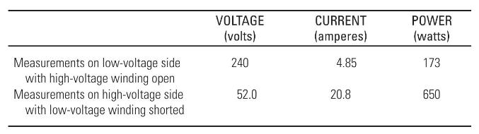
The following data are obtained when open-circuit and short-circuit tests are performed on a single-phase, \(50-\mathrm{kVA}, 2400 / 240\)-volt, \(60-\mathrm{Hz}\) distribution transformer.(a) Neglecting the series impedance, determine the exciting admittance referred to the high-voltage side. (b)
A single-phase 50-kVA, 2400/240-volt, \(60-\mathrm{Hz}\) distribution transformer has a 1 -ohm equivalent leakage reactance and a 5000 -ohm magnetizing reactance referred to the high-voltage side. If rated voltage is applied to the high-voltage winding, calculate the open-circuit secondary voltage.
A single-phase 50-kVA, 2400/240-volt, 60-Hz distribution transformer is used as a step-down transformer at the load end of a 2400 -volt feeder whose series impedance is \((1.0+j 2.0)\) ohms. The equivalent series impedance of the transformer is \((1.0+j 2.5)\) ohms referred to the highvoltage
Rework Problem 3.14 if the transformer is delivering rated load at rated secondary voltage and at(a) unity power factor,(b) 0.8 power factor leading. Compare the results with those of Problem 3.14.Problem 3.14A single-phase 50-kVA, 2400/240-volt, 60-Hz distribution transformer is used as a
A single-phase, \(50-\mathrm{kVA}, 2400 / 240-\mathrm{V}, 60-\mathrm{Hz}\) distribution transformer has the following parameters:Resistance of the \(2400-\mathrm{V}\) winding: \(\mathrm{R}_{1}=0.75 \Omega\)Resistance of the \(240-\mathrm{V}\) winding: \(\mathrm{R}_{2}=0.0075 \Omega\)Leakage
The transformer of Problem 3.16 is supplying a rated load of \(50 \mathrm{kVA}\) at a rated sec ondary voltage of \(240 \mathrm{~V}\) and at 0.8 power factor lagging. Neglect the transformer exciting current.(a) Determine the input terminal voltage of the transformer on the high-voltage side.(b)
Using the transformer ratings as base quantities, work Problem 3.13 in per-unit.Problem 3.13A single-phase 50-kVA, 2400/240-volt, \(60-\mathrm{Hz}\) distribution transformer has a 1 -ohm equivalent leakage reactance and a 5000 -ohm magnetizing reactance referred to the high-voltage side. If rated
Using the transformer ratings as base quantities, work Problem 3.14 in per-unit.Problem 3.14A single-phase 50-kVA, 2400/240-volt, 60-Hz distribution transformer is used as a step-down transformer at the load end of a 2400 -volt feeder whose series impedance is \((1.0+j 2.0)\) ohms. The equivalent
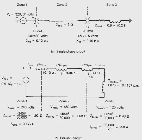
Using base values of \(20 \mathrm{kVA}\) and 115 volts in zone 3, rework Example 3.4.Example 3.4Three zones of a single-phase circuit are identified in Figure 3.10(a). The zones are connected by transformers \(T_{1}\) and \(T_{2}\), whose ratings are also shown. Using base values of \(30
Rework Example 3.5; using \(\mathrm{S}_{\text {base } 3 \phi}=100 \mathrm{kVA}\) and \(\mathrm{V}_{\text {baseLL }}=600\) volts.Example 3.5As in Example 2.5, a balanced-Y-connected voltage source with \(E_{a b}=480 \angle 0^{\circ}\) volts is applied to a balanced- \(\Delta\) load with
A balanced Y-connected voltage source with \(E_{a g}=277 / 0^{\circ}\) volts is applied to a balanced- \(Y\) load in parallel with a balanced- \(\Delta\) load where \(Z_{Y}=20+\) \(j 10\) and \(Z \Delta=30-j 15\) ohms. The \(\mathrm{Y}\) load is solidly grounded. Using base values of \(S_{\text
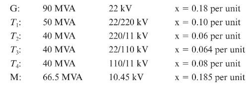
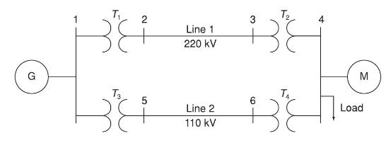
Figure 3.32 shows the oneline diagram of a three-phase power system. By selecting a common base of 100 MVA and \(22 \mathrm{kV}\) on the generator side, draw an impedance diagram showing all impedances including the load impedance in per-unit. The data are given as follows:Lines 1 and 2 have series
For Problem 3.18, the motor operates at full load, at 0.8 power factor leading, and at a terminal voltage of \(10.45 \mathrm{kV}\). Determine (a) the voltage at bus 1 , which is the generator bus, and (b) the generator and motor internal EMFs.Problem 3.18Using the transformer ratings as base
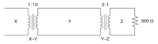
Consider a single-phase electric system shown in Figure 3.33. Transformers are rated as follows:X-Y 15 MVA, 13.8/138 kV, leakage reactance 10\%Y-Z 15 MVA, 138/69 kV, leakage reactance 8\%With the base in circuit Y chosen as \(15 \mathrm{MVA}, 138 \mathrm{kV}\), determine the perunit impedance of
A bank of three single-phase transformers, each rated 30 MVA, \(38.1 / 3.81 \mathrm{kV}\), are connected in \(\mathrm{Y}-\Delta\) with a balanced load of three \(1 \Omega\), Y-connected resistors. Choosing a base of 90 MVA, \(66 \mathrm{kV}\) for the high-voltage side of the three-phase
A three-phase transformer is rated \(1000 \mathrm{MVA}, 220 \mathrm{Y} / 22 \Delta \mathrm{kV}\). The Y-equivalent short-circuit impedance, considered equal to the leakage reactance, measured on the low-voltage side is \(0.1 \Omega\). Compute the per-unit reactance of the transformer. In a system
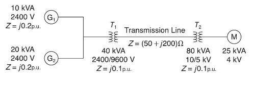
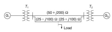
For the system shown in Figure 3.34, draw an impedance diagram in per unit by choosing \(100 \mathrm{kVA}\) to be the base kVA and \(2400 \mathrm{~V}\) as the base voltage for the generators. 10 KVA 2400 V G Z= j0.2p.u. 20 KVA 2400 V Z=j0.2p.u. G T Transmission Line Z = (50+j200) 40 KVA 2400/9600 V
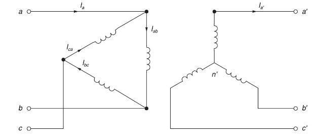
Consider three ideal single-phase transformers (with a voltage gain of \(\eta\) ) put together as a \(\Delta-\Omega\) three-phase bank as shown in Figure 3.35. Assuming positive-sequence voltages for \(V_{a w}, V_{b n}\), and \(V_{c n}\), find \(V_{a^{\prime} n^{\prime}}, V_{b^{\prime}
Reconsider Problem 3.29. If \(V_{a n}, V_{b n}\), and \(V_{c n}\) are a negative-sequence set, how would the voltage and current relationships change?(a) If \(C_{1}\) is the complex positive-sequence voltage gain in Problem 3.29 and(b) if \(C_{2}\) is the negative sequence complex voltage gain,
If positive-sequence voltages are assumed and the Y- \(\Delta\) connection is considered, again with ideal transformers as in Problem 3.29, find the complex voltage gain \(C_{3}\).(a) What would the gain be for a negative-sequence set?(b) Comment on the complex power gain.(c) When terminated in a
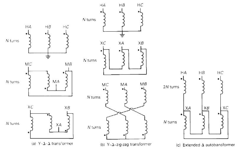
Determine the positive- and negative-sequence phase shifts for the threephase transformers shown in Figure 3.36. N turns. N turns N turns. HA HB 111 MC XC MA HC MB XB (a) Y-1-1 transformer N turns N turns HA N turns. N turns HB H XB LU MC MA MB (b) Y-3-zig-zag transformer 2N turns N turns HA HC
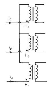
Consider the three single-phase two-winding transformers shown in Figure 3.37. The high-voltage windings are connected in Y.(a) For the low-voltage side, connect the windings in \(\Delta\), place the polarity marks, and label the terminals \ (a, b\), and \(c\) in accordance with the American
Three single-phase, two-winding transformers, each rated 450 MVA, \(20 \mathrm{kV} / 288.7 \mathrm{kV}\), with leakage reactance \(\mathrm{X}_{\mathrm{eq}}=0.10\) per unit, are connected to form a three-phase bank. The high-voltage windings are connected in \(Y\) with a solidly grounded neutral.
Consider a bank of three single-phase two-winding transformers whose high-voltage terminals are connected to a three-phase, \(13.8-\mathrm{kV}\) feeder. The low-voltage terminals are connected to a three-phase substation load rated 2.0 MVA and \(2.5 \mathrm{kV}\). Determine the required voltage,
Three single-phase two-winding transformers, each rated 25 MVA, \(34.5 / 13.8 \mathrm{kV}\), are connected to form a three-phase \(\Delta-\Delta\) bank. Balanced positive-sequence voltages are applied to the high-voltage terminals, and a balanced, resistive Y load connected to the low-voltage
Three single-phase two-winding transformers, each rated 25 MVA, 54.2/5.42kV54.2/5.42kV, are connected to form a three-phase Y−ΔY−Δ bank with a balanced Y-connected resistive load of 0.6Ω0.6Ω per phase on the low-voltage side. By choosing a base of 75 MVA (three phase) and 94kV94kV
Consider a three-phase generator rated \(300 \mathrm{MVA}, 23 \mathrm{kV}\), supplying a system load of \(240 \mathrm{MVA}\) and 0.9 power factor lagging at \(230 \mathrm{kV}\) through a 330 MVA, \(23 \Delta / 230 \mathrm{Y}-\mathrm{kV}\) step-up transformer with a leakage reactance of 0.11 per
The leakage reactance of a three-phase, \(300-\mathrm{MVA}, 230 \mathrm{Y} / 23 \Delta-\mathrm{kV}\) transformer is 0.06 per unit based on its own ratings. The \(\mathrm{Y}\) winding has a solidly grounded neutral. Draw the per-unit equivalent circuit. Neglect the exciting admittance and assume the
Choosing system bases to be \(240 / 24 \mathrm{kV}\) and 100 MVA, redraw the perunit equivalent circuit for Problem 3.39.Problem 3.39The leakage reactance of a three-phase, \(300-\mathrm{MVA}, 230 \mathrm{Y} / 23 \Delta-\mathrm{kV}\) transformer is 0.06 per unit based on its own ratings. The
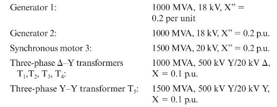
Consider the single-line diagram of the power system shown in Figure 3.38. Equipment ratings areNeglecting resistance, transformer phase shift, and magnetizing reactance, draw the equivalent reactance diagram. Use a base of 100 MVA and \(500 \mathrm{kV}\) for the 50 -ohm line. Determine the
For the power system in Problem 3.41, the synchronous motor absorbs \(1500 \mathrm{MW}\) at 0.8 power factor leading with the bus 3 voltage at \(18 \mathrm{kV}\). Determine the bus 1 and bus 2 voltages in \(\mathrm{kV}\). Assume that generators 1 and 2 deliver equal real powers and equal reactive
Three single-phase transformers, each rated \(10 \mathrm{MVA}, 66.4 / 12.5 \mathrm{kV}, 60 \mathrm{~Hz}\), with an equivalent series reactance of 0.1 per unit divided equally between primary and secondary, are connected in a three-phase bank. The highvoltage windings are Y-connected and their
A 130-MVA, 13.2-kV three-phase generator, which has a positivesequence reactance of 1.5 per unit on the generator base, is connected to a 135-MVA, \(13.2 \Delta / 115 \mathrm{Y}-\mathrm{kV}\) step-up transformer with a series impedance of \((0.005+j 0.1)\) per unit on its own base. (a) Calculate
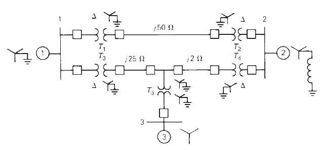
Figure 3.39 shows a oneline diagram of a system in which the three-phase generator is rated \(300 \mathrm{MVA}, 20 \mathrm{kV}\) with a subtransient reactance of 0.2 per unit and with its neutral grounded through a \(0.4-\Omega\) reactor. The transmission line is \(64 \mathrm{~km}\) long with a
The motors \(M_{1}\) and \(M_{2}\) of Problem 3.45 have inputs of 120 and \(60 \mathrm{MW}\), respectively, at \(13.2 \mathrm{kV}\), and both operate at unity power factor. Determine the generator terminal voltage and voltage regulation of the line. Neglect transformer phase shifts.Problem
Consider the oneline diagram shown in Figure 3.40. The three-phase transformer bank is made up of three identical single-phase transformers, each specified by \(X_{1}=0.24 \Omega\) (on the low-voltage side), negligible resistance and magnetizing current, and turns ratio \(\eta=N_{2} / N_{1}=10\).
With the same transformer banks as in Problem 3.47, Figure 3.41 shows the oneline diagram of a generator, a step-up transformer bank, a transmission line, a step-down transformer bank, and an impedance load. The generator terminal voltage is \(15 \mathrm{kV}\) (line-to-line).(a) Draw the per-phase
Consider the single-line diagram of a power system shown in Figure 3.42 with equipment ratings given:Choose a base of 100 MVA for the system and \(132-\mathrm{kV}\) base in the transmission-line circuit. Let the load be modeled as a parallel combination of resistance and inductance. Neglect
A single-phase three-winding transformer has the following parameters: \(Z_{1}=Z_{2}=Z_{3}=0+j 0.05, \mathrm{G}_{C}=0\), and \(\mathrm{B}_{M}=0.2\) per unit. Three identical transformers, as described, are connected with their primaries in \(\mathrm{Y}\) (solidly grounded neutral) and with their
The ratings of a three-phase three-winding transformer are Primary (1): Y connected, \(66 \mathrm{kV}, 15\) MVASecondary (2): Y connected, \(13.2 \mathrm{kV}, 10\) MVATertiary (3): A connected, \(2.3 \mathrm{kV}, 5 \mathrm{MVA}\)Neglecting winding resistances and exciting current, the per-unit
Draw the per-unit equivalent circuit for the transformers shown in Figure 3.34. Include ideal phase-shifting transformers showing phase shifts determined in Problem 3.32. Assume that all windings have the same \(\mathrm{kVA}\) rating and that the equivalent leakage reactance of any two windings
The ratings of a three-phase, three-winding transformer are Primary: Y connected, 66kV,15MVA66kV,15MVASecondary: Y connected, 13.2 kV, 10 MVATertiary: ΔΔ connected, 2.3kV,5MVA2.3kV,5MVANeglecting resistances and exciting current, the leakage reactances are:XPS=0.09 per unit on
An infinite bus, which is a constant voltage source, is connected to the primary of the three-winding transformer of Problem 3.53. A 7.5-MVA, 13.2-kV synchronous motor with a subtransient reactance of 0.2 per unit is connected to the transformer secondary. A \(5-\mathrm{MW}, 2.3-\mathrm{kV}\)
A single-phase \(10-\mathrm{kVA}, 2300 / 230-\) volt, \(60-\mathrm{Hz}\) two-winding distribution transformer is connected as an autotransformer to step up the voltage from 2300 to 2530 volts. (a) Draw a schematic diagram of this arrangement, showing all voltages and currents when delivering full
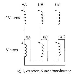
Three single-phase two-winding transformers, each rated \(3 \mathrm{kVA}, 220 / 110\) volts, \(60 \mathrm{~Hz}\), with a 0.10 per-unit leakage reactance, are connected as a three-phase extended \(\Delta\) autotransformer bank, as shown in Figure 3.36 (c). The low-voltage \(\Delta\) winding has a
A two-winding single-phase transformer rated 60kVA,240/1200 V,60 Hz60kVA,240/1200 V,60 Hz60kVA,240/1200 V,60 Hz, has an efficiency of 0.96 when operated at rated load, 0.8 power factor lagging. This transformer is to be utilized as a 1440/1200-V step-down
A single-phase two-winding transformer rated \(90 \mathrm{MVA}, 80 / 120 \mathrm{kV}\) is to be connected as an autotransformer rated \(80 / 200 \mathrm{kV}\). Assume that the transformer is ideal. (a) Draw a schematic diagram of the ideal transformer connected as an autotransformer, showing the
The two parallel lines in Example 3.13 supply a balanced load with a load current of 1.0∠−30∘1.0∠−30∘ per unit. Determine the real and reactive power supplied to the load bus from each parallel line with(a) no regulating transformer,(b) the voltage-magnitude-regulating transformer in
PowerWorld Simulator case Problem 3_60 duplicates Example 3.13 except that a resistance term of 0.06 per unit has been added to the transformer and 0.05 per unit to the transmission line. Since the system is no longer lossless, a field showing the real power losses has also been added to the
Repeat Problem 3.60, except keep the phase-shift angle fixed at 3.0 degrees while varying the LTC tap between 0.9 and 1.1. What tap value minimizes the real power losses?Problem 3.60PowerWorld Simulator case Problem 3_60 duplicates Example 3.13 except that a resistance term of 0.06 per unit has
Rework Example 3.12 for a \(+10 \%\) tap, providing a \(10 \%\) increase for the high-voltage winding.Example 3.12A three-phase generator step-up transformer is rated \(1000 \mathrm{MVA}, 13.8 \mathrm{kV} \Delta / 345 \mathrm{kV}\) \(\mathrm{Y}\) with \(Z_{\mathrm{eq}}=j 0.10\) per unit. The
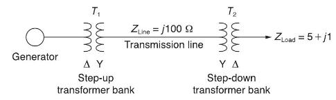
A \(23 / 230-\mathrm{kV}\) step-up transformer feeds a three-phase transmission line, which in turn supplies a 150-MVA, 0.8 lagging power factor load through a step-down \(230 / 23-\mathrm{kV}\) transformer. The impedance of the line and transformers at \(230 \mathrm{kV}\) is \(18+j 60 \Omega\).
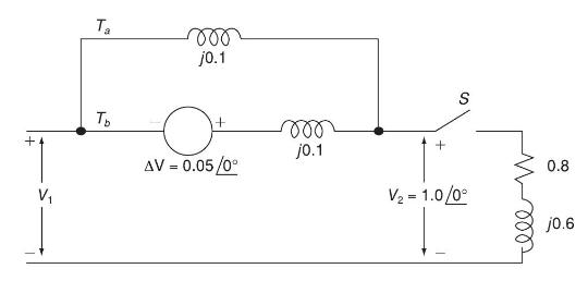
The per-unit equivalent circuit of two transformers \(T_{a}\) and \(T_{b}\) connected in parallel, with the same nominal voltage ratio and the same reactance of 0.1 per unit on the same base, is shown in Figure 3.43. Transformer \(T_{b}\) has a voltage-magnitude step-up toward the load of 1.05
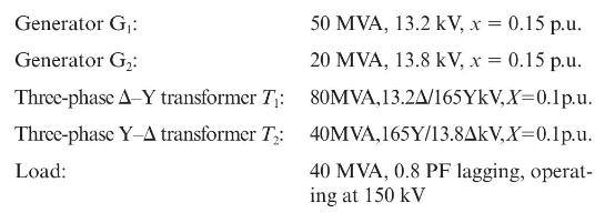
Reconsider Problem 3.64 with the change that now \(T_{b}\) includes both a transformer of the same turns ratio as \(T_{a}\) and a regulating transformer with a \(4^{\circ}\) phase shift. On the base of \(T_{a}\), the impedance of the two components of \(T_{b}\) is \(j 0.1\) per unit. Determine the
ACSR stands for(a) Aluminum-clad steel conductor(b) Aluminum conductor steel supported(c) Aluminum conductor steel reinforced
Overhead transmission-line conductors are bare with no insulating cover.(a) True(b) False
Alumoweld is an aluminum-clad steel conductor.(a) True(b) False
EHV lines often have more than one conductor per phase; these conductors are called a
Shield wires located above the phase conductors protect the phase conductors against lightning.(a) True(b) False
Conductor spacings, types, and sizes do have an impact on the series impedance and shunt admittance.(a) True(b) False
A circle with diameter \(D\) in. \(=1000 D\) mil \(=d\) mil has an area of \(c\) mil.
An ac resistance is higher than a dc resistance.(a) True(b) False
Match the following for the current distribution throughout the conductor cross section:(i) For dc(a) uniform(ii) For ac(b) nonuniform
Transmission line conductance is usually neglected in power system studies.(a) True(b) False
The internal inductance \(L_{\text {int }}\) per unit-length of a solid cylindrical conductor is a constant, given by \(\frac{1}{2} \times 10^{-7} \mathrm{H} / \mathrm{m}\) in SI system of units.(a) True(b) False
The total inductance \(L_{\mathrm{P}}\) of a solid cylindrical conductor (of radius \(r\) ) due to both internal and external flux linkages out of distance \(\mathrm{D}\) is given by (in \(\mathrm{H} / \mathrm{m}\) )(a) \(2 \times 10^{-7}\)(b) \(4 \times 10^{-7} \ln
For a single-phase, two-wire line consisting of two solid cylindrical conductors of same radius, \(r\), the total circuit inductance, also called loop inductance, is given by (in \(\mathrm{H} / \mathrm{m}\) )(a) \(2 \times 10^{-7} \ln \left(\frac{\mathrm{D}}{r^{\prime}}ight)\)(b) \(4 \times 10^{-7}
For a three-phase three-wire line consisting of three solid cylindrical conductors, each with radius \(r\) and with equal phase spacing \(\mathrm{D}\) between any two conductors, the inductance in \(\mathrm{H} / \mathrm{m}\) per phase is given by(a) \(2 \times 10^{-7} \ln
For a balanced three-phase positive-sequence currents \(I_{a}, I_{b}, I_{c}\), does the equation \(I_{a}+I_{b}+I_{c}=0\) hold good?
A stranded conductor is an example of a composite conductor.(a) True(b) False
\(\Sigma \ln A_{k}=\ln \Pi A_{k}\)(a) True(b) False
Is Geometric Mean Distance (GMD) the same as Geometric Mean Radius (GMR)?(a) Yes(b) No
Expand \(6 \sqrt{\Pi_{k=1}^{3} \Pi_{m=1^{\prime}}^{2^{\prime}} \mathrm{D}_{k m}}\).
If the distance between conductors are large compared to the distances between subconductors of each conductor, then the GMD between conductors is approximately equal to the distance between conductor centers.(a) True(b) False
For a single-phase two-conductor line with composite conductors \(x\) and \(y\), express the inductance of conductor \(x\) in terms of GMD and its GMR.
In a three-phase line, in order to avoid unequal phase inductances due to unbalanced flux linkages, what technique is used?
Showing 3700 - 3800
of 5433
First
31
32
33
34
35
36
37
38
39
40
41
42
43
44
45
Last
Step by Step Answers