New Semester
Started
Get
50% OFF
Study Help!
--h --m --s
Claim Now
Question Answers
Textbooks
Find textbooks, questions and answers
Oops, something went wrong!
Change your search query and then try again
S
Books
FREE
Study Help
Expert Questions
Accounting
General Management
Mathematics
Finance
Organizational Behaviour
Law
Physics
Operating System
Management Leadership
Sociology
Programming
Marketing
Database
Computer Network
Economics
Textbooks Solutions
Accounting
Managerial Accounting
Management Leadership
Cost Accounting
Statistics
Business Law
Corporate Finance
Finance
Economics
Auditing
Tutors
Online Tutors
Find a Tutor
Hire a Tutor
Become a Tutor
AI Tutor
AI Study Planner
NEW
Sell Books
Search
Search
Sign In
Register
study help
engineering
mechanics of materials
Mechanics Of Materials 9th Edition Barry J Goodno, James M Gere - Solutions
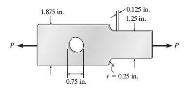
Determine the maximum axial force P that can be applied to the bar. The allowable stress is σ allow = 21 ksi. P 1.875 in. 0.125 in. 1.25 in. 0.75 in. r = 0.25 in. P
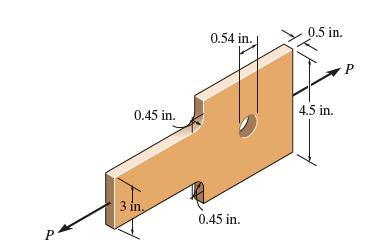
Determine the maximum axial force P that can be applied to the plate. The allowable stress is σ allow = 36 ksi. P 0.5 in. 0.54 in. P 0.45 in. 4.5 in. 3 in, 0.45 in.
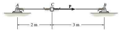
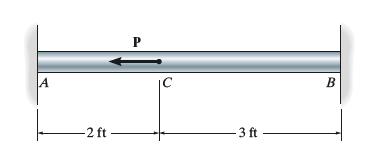
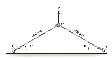
Two steel wires, each having a cross-sectional area of 2 mm2 are tied to a ring at C, and then stretched and tied between the two pins A and B. The initial tension in the wires is 50 N. If a horizontal force P is applied to the ring, determine the force in each wire if P = 20 N. What is the
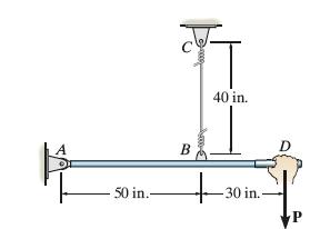
The wire BC has a diameter of 0.125 in. and the material has the stress–strain diagram shown. Determine the vertical displacement of the handle at D if the pull at the grip is slowly increased and reaches a magnitude of (a) P = 450 lb,(b) P = 600 lb. Assume the bar is rigid. A B 40 in. 50 in.-
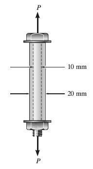
The 10-mm-diameter shank of the steel bolt has a bronze sleeve bonded to it. The outer diameter of this sleeve is 20 mm. If the yield stress for the steel is (σy)st = 640 MPa, and for the bronze (σy) br = 520 MPa, determine the largest possible value of P that can be applied to the bolt. Assume
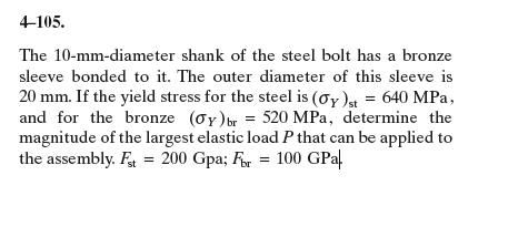
The 10-mm-diameter shank of the steel bolt has a bronze sleeve bonded to it. The outer diameter of this sleeve is 20 mm. If the yield stress for the steel is (σy)st = 640 MPa, and for the bronze (σy) br = 520 MPa, determine the magnitude of the largest elastic load P that can be applied to the
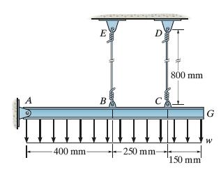
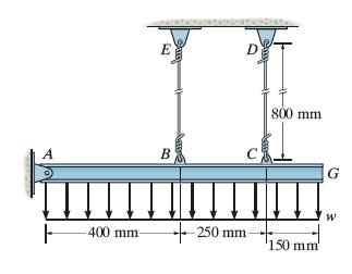
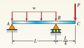
The rigid beam is supported by a pin at A and two steel wires, each having a diameter of 4 mm. If the yield stress for the wires is σy = 530 MPa, and Est = 200 GPa, determine the intensity of the distributed load w that can be placed on the beam and will just cause wire EB to yield. What is the
The rigid beam is supported by a pin at A and two steel wires, each having a diameter of 4 mm. If the yield stress for the wires is σy = 530 MPa, and Est = 200 GPa, determine (a) the intensity of the distributed load w that can be placed on the beam that will cause only one of the wires to start
The 2-in.-diameter bar is fixed connected at its ends and supports the axial load P. If the material is elastic perfectly plastic as shown by the stress–strain diagram, determine the smallest load P needed to cause segment CB to yield.Determine the elongation of the bar when both the load P and
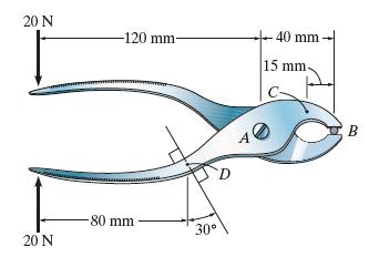
Determine the resultant internal loading on the cross section through point C of the pliers. There is a pin at A, and the jaws at B are smooth. 20 N -120 mm- 40 mm 15 mm- 80 mm 30 20 N B
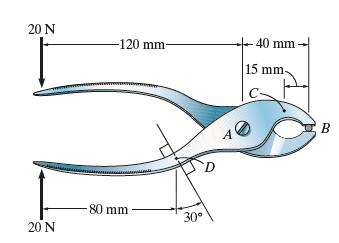
Determine the resultant internal loading on the cross section through point D of the pliers. There is a pin at A, and the jaws at B are smooth. 20 N -120 mm- 40 mm 15 mm- 80 mm 30 20 N D B
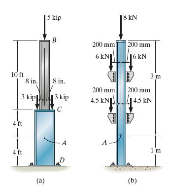
Determine the resultant internal normal force acting on the cross section through point A in each column. In (a), segment BC weighs 180 lb ft and segment CD weighs 250 lb ft. In(b), the column has a mass of 200 kg m. 5 kip 18 kN B 200 mm 200 mm 6 kN 16 kN 10 ft 3 m 8 in. 8 in. 200 mm 200 mm 3 kip 3
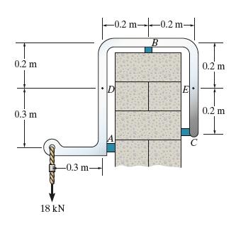
The sky hook is used to support the cable of a scaffold over the side of a building. If it consists of a smooth rod that contacts the parapet of a wall at points A, B, and C, determine the normal force, shear force, and moment on the cross section at points D and E. 0.2 m 0.3 m -0.3 m- 18 kN -0.2
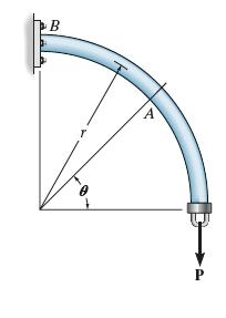
The curved rod has a radius r and is fixed to the wall at B.Determine the resultant internal loadings acting on the cross section at point A which is located at an angle from the horizontal. B P
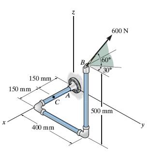
The pipe assembly is subjected to a force of 600 N at B. Determine the resultant internal loading acting on the cross section at point C. 150 mm 150 mm 400 mm 2 B 60 30 A 500 mm 600 N
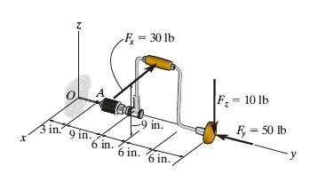
If the drill bit jams when the handle of the hand drill is subjected to the forces shown, determine the resultant internal loadings acting on the cross section of the drill bit at A. Z F-30 lb 9 in. F= 10 lb R = 50 lb y 3 in 9 in. 6 in. 6 in. 6 in.
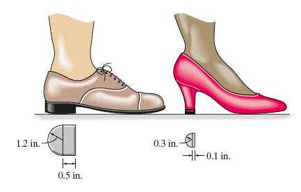
A 175-lb woman stands on a vinyl floor wearing stiletto highheel shoes. If the heel has the dimensions shown, determine the average normal stress she exerts on the floor and compare it with the average normal stress developed when a man having the same weight is wearing flat-heeled shoes.Assume the
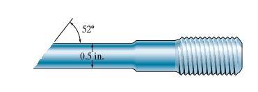
The specimen failed in a tension test at an angle of 52° when the axial load was 19.80 kip. If the diameter of the specimen is 0.5 in., determine the average normal and average shear stress acting on the area of the inclined failure plane. Also, what is the average normal stress acting on the
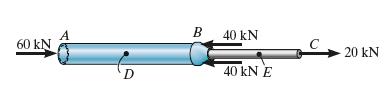
The built-up shaft consists of a pipe AB and solid rod BC.The pipe has an inner diameter of 25 mm and outer diameter of 30 mm. The rod has a diameter of 15 mm. Determine the average normal stress at points D and E and represent the stress on a volume element located at each of these points. 60 kN D
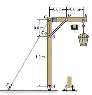
The 150-kg bucket is suspended from end E of the frame. Determine the avarage normal stress in the 6-mm diameter wire CF and the 15-mm diameter short struct BD. 0.6 m 30 1.2 m 0.6 m 0.6 m D B A E
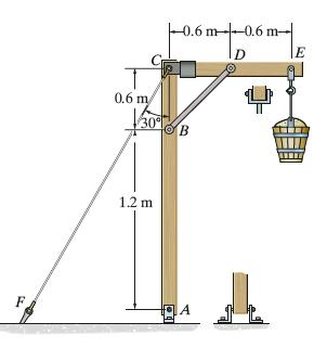
The 150-kg bucket is suspended from end E of the frame. If the diameters of the pins at A and D are 6 mm and 10 mm, respectively, determine the average shear stress developed in these pins. Each pin is subjected to double shear. -0.6 m-0.6 m- D 0.6 m 30 B 1.2 m F FA E
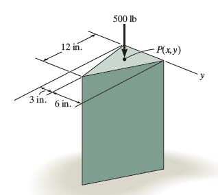
If the pedestal is subjected to a compressive force of 500 lb, specify the x and y coordinates for the location of point P(x, y), where the load must be applied on the cross section, so that the average normal stress is uniform. Calculate the stress and sketch its distribution acting on the cross
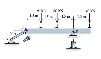
The beam is supported by a pin at B and a short link AC.Determine the average shear stress developed in the pins at A, B, and C. All pins are in double shear as shown, and each has a diameter of 30 mm. A 80 kN 80 kN 40 kN 1.5 m 1.5 m 1.5 m 1.5 m
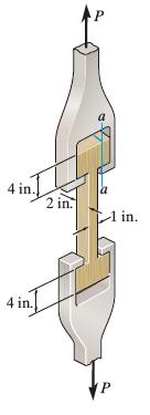
During a tension test, the wooden specimen is subjected to an average normal stress of 2 ksi. Determine the axial force P applied to the specimen. Also, find the average shear stress developed along section a–a of the specimen. 4 in. 2 in. 1 in. in. P
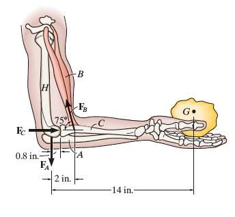
When the hand is holding the 5-lb stone, the humerus H, assumed to be smooth, exerts normal forces FC and FA on the radius C and ulna A, respectively, as shown. If the smallest cross-sectional area of the ligament at B is 0.30 in2, determine the greatest average tensile stress to which it is
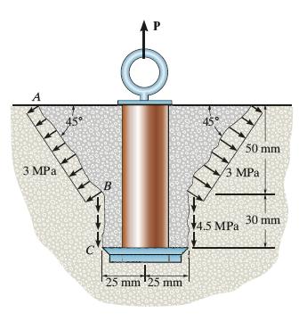
The anchor bolt was pulled out of the concrete wall and the failure surface formed part of a frustum and cylinder. This indicates a shear failure occurred along the cylinder BC and tension failure along the frustum AB. If the shear and normal stresses along these surfaces have the magnitudes shown,
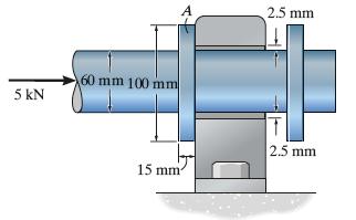
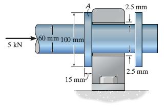
If the shaft is subjected to an axial force of 5 kN, determine the bearing stress acting on the collar A. 5 kN 60 mm 100 mm 2.5 mm 15 mm 2.5 mm
If the 60-mm diameter shaft is subjected to an axial force of 5 kN, determine the average shear stress developed in the shear plane where the collar A and shaft are connected. 5 kN 60 mm 100 mm 2.5 mm 15 mm- 2.5 mm
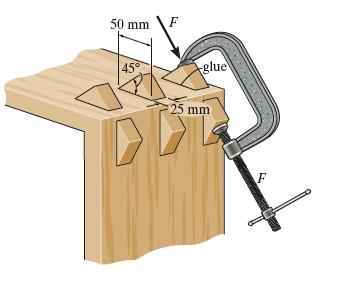
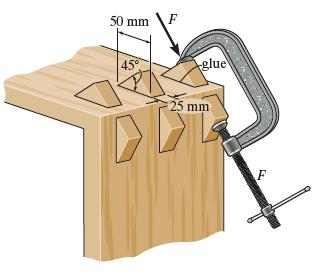
The triangular blocks are glued along each side of the joint.A C-clamp placed between two of the blocks is used to draw the joint tight. If the glue can withstand a maximum average shear stress of 800 kPa, determine the maximum allowable clamping force F. 50 mm 45 glue 25 mm F
The triangular blocks are glued along each side of the joint. A C-clamp placed between two of the blocks is used to draw the joint tight. If the clamping force is F = 900N, determine the average shear stress developed within the glued shear plane. 50 mm 45 glue 25 mm F
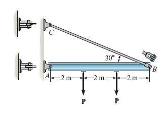
If P = 20 kN, determine the average shear stress developed in the pins at A and C. All pins are subjected to double shear as shown, and each has a diameter of 18 mm. A-2 m- m P 30 -2m- B
Determine the maximum magnitude P of the load the beam will support if the average shear stress in each pin is not allowed to exceed 60 MPa. All pins are subjected to double shear as shown, and each has a diameter of 18 mm. 30 A-2 m- -2 m +2 P P -2 m- B
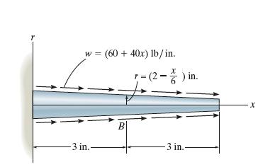
The tapered rod has a radius of r = (2 − x/6) in.and is subjected to the distributed loading of w = (60 + 40x) lb/in. Determine the average normal stress at the center of the rod, B. w= (60+40x) lb/in. =(2-) in. -3 in.- B -3 in. x
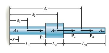
Consider the general problem of a bar made from m segments, each having a constant cross-sectional area Am and length Lm. If there are n loads on the bar as shown, write a computer program that can be used to determine the average normal stress at any specified location x. Show an application of
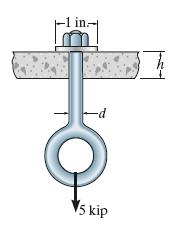
The eye bolt is used to support the load of 5 kip. Determine its diameter d to the nearest 1/8 in. and the required thickness h to the nearest 1/8 in. of the support so that the washer will not penetrate or shear through it. The allowable normal stress for the bolt is σallow = 21 ksi and the
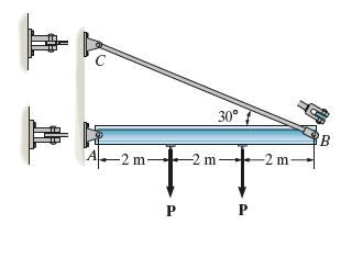
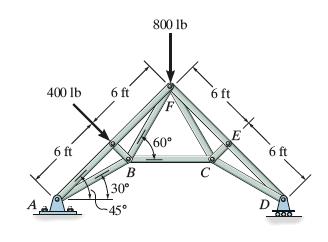
Determine the required cross-sectional area of member BC if the allowable normal stress is σallow = 24 ksi. 800 lb 400 lb 6 ft 6 ft B 60 6 ft 30 -45' D 6 ft
The hangers support the joist in such a way that the four nails on each hanger can be assumed to support an equal portion of the load. If the joist is subjected to the loading shown, determine the average shear stress in each nail of the hanger at ends A and B. Each nail has a diameter of 3/16 in.
The hangers support the joist in such a way that the four nails on each hanger can be assumed to support an equal portion of the load. Determine the smallest diameter of the nails at A and B to the nearest 1/16 in. if the allowable shear stress for the nails is σallow = 6.5 ksi. The hangers only
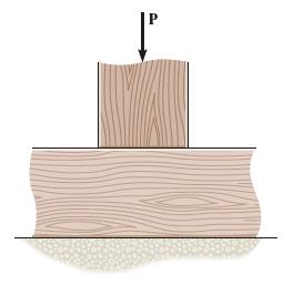
The 60 mm x 60 mm oak post is supported on the pine block. If the allowable bearing stresses for these materials are σoak = 43 MPa and σpine 25 MPa, determine the greatest load P that can be supported. If a rigid bearing plate is used between these materials, determine its required area so that
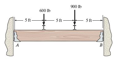
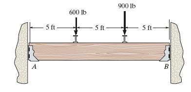
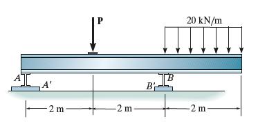
If the allowable bearing stress for the plates under the supports at A and B is ( σb )allow =1.8 MPa, determine the size of square bearing plates A′ and B′ required to support the load. Dimension the plates to the nearest mm. The reactions at the supports are vertical. Take P = 150 kN. A' 2m-
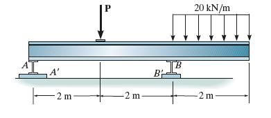
If the allowable bearing stress for the plates under the supports at A and B is (σb )allow =1.8 MPa, determine the maximum load P that can be applied to the beam.The plates A′ and B′ have square cross sections of 200mm × 200mm and 300mm × 300mm, respectively. B B 2 m -2 m 20 kN/m 2 m
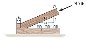
Member B is subjected to a compressive force of 910 lb. If A and B are both made of wood and are 1/2 in. thick, determine to the nearest 1/8 in. the smallest dimension b of the horizontal segment so that it does not fail in shear. The allowable average shear stress for the segment is τallow = 275
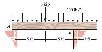
The beam is made from southern pine and is supported by base plates resting on brickwork. If the allowable bearing stresses for the materials are (σpine ) allow = 2.81 ksi and ( σbrick )allow = 6.70 ksi, determine the required length of the base plates at A and B to the nearest 1/4 inch in order
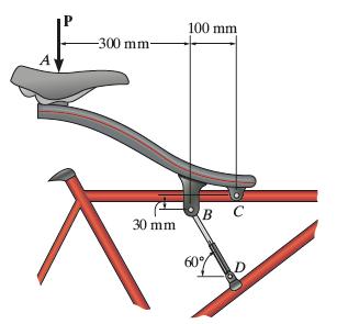
The soft-ride suspension system of the mountain bike is pinned at C and supported by the shock absorber BD. If it is designed to support a load P = 1500 N, determine the required minimum diameter of pins B and C. Use a factor of safety of 2 against failure. The pins are made of material having a
The soft-ride suspension system of the mountain bike is pinned at C and supported by the shock absorber BD. If it is designed to support a load of P = 1500 N, determine the factor of safety of pins B and C against failure if they are made of a material having a shear failure stress of τfail = 150
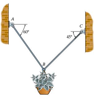
The 60-kg flowerpot is suspended from wires AB and BC. If the wires have a failure normal stress of σfail = 380 MPa, determine the minimum diameter of each wire. Use a factor of safety of 2. A 60 45 B C
The 60-kg flowerpot is suspended from wires AB and BC which have diameters of 1.75 mm and 1.5 mm, respectively.If the wires have a failure normal stress of σfail = 380 MPa, determine the factor of safety of each wire. A /60 B 45 C
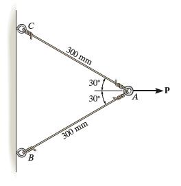
The two wires are connected together at A. If the force P causes point A to be displaced horizontally 2 mm, determine the normal strain developed in each wire. C 300 mm 30 B 300 mm 30 A -P
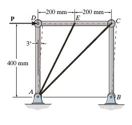
The force P applied at joint D of the square frame causes the frame to sway and form the dashed rhombus. Determine the average normal strain developed in wire AC. Assume the three rods are rigid. P -200 mm-200 mm- E 3 400 mm A B
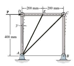
The force P applied at joint D of the square frame causes the frame to sway and form the dashed rhombus. Determine the average normal strain developed in wire AE. Assume the three rods are rigid. -200 mm- -200 mm- P D E C 400 mm 3 B
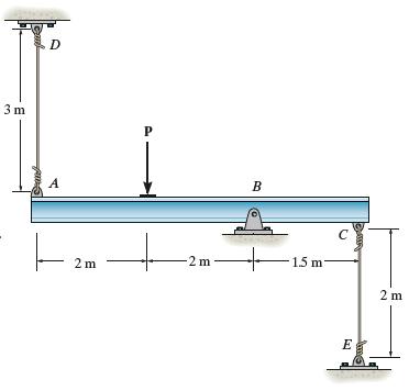
The rigid beam is supported by a pin at B and wires AD and CE. If the load P on the beam causes the end A to be displaced 6 mm downward, determine the normal strain developed in wires CE and AD. The wires are unstretched when the beam is in horizontal position. D 3 m P A B C 2 m -2 m +1 1.5 m 2 m E
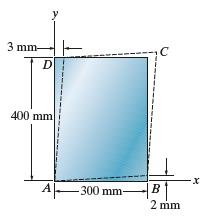
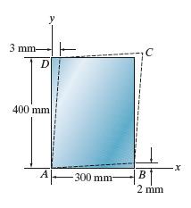
The piece of rubber is originally rectangular. Determine the average shear strain γxy at A if the corners B and D are subjected to the displacements that cause the rubber to distort as shown by the dashed lines.. 3 mm- D 400 mm A 300 mm- B 2 mm x
The piece of rubber is originally rectangular and subjected to the deformation shown by the dashed lines. Determine the average normal strain along the diagonal DB and side AD. 3 mm- D 400 mm -x A -300 mm- B 2 mm
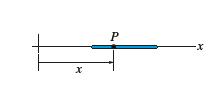
A thin wire, lying along the x axis, is strained such that each point on the wire is displaced Δx = kx2 along the x axis. If k is constant, what is the normal strain at any point P along the wire? x P -x
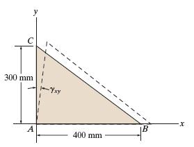
The triangular plate ABC is deformed into the shape shown by the dashed lines. If at A, εAB = 0.0075, εAC = 0.01 and γxy = 0.005 rad, determine the average normal strain along edge BC. C y 300 mm -Yxy A 400 mm B x
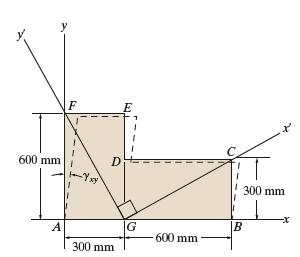
The plate is deformed uniformly into the shape shown by the dashed lines. If at A, γxy = 0.0075 rad., while εAB = εAF 0, determine the average shear strain at point G with respect to the x' and y' axes. y F 600 mm Yxy D 300 mm -x A G B 600 mm 300 mm
If the force P causes point A to be displaced vertically by 2.2 mm, determine the normal strain developed in each wire. 600 mm B 30 P 600 mm 30 C
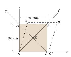
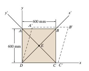
The square plate is deformed into the shape shown by the dashed lines. If DC has a normal strain εx= 0.004, DA has a normal strain εy = 0.005 and at D, Yxy = 0.02 rad, determine the average normal strain along diagonal CA. A' 600 mm E 600 mm -B' B D C C' -x
The square plate ABCD is deformed into the shape shown by the dashed lines. If DC has a normal strain εx = 0.004, DA has a normal strain εx= 0.005, and at D, Yxy = 0.02 rad, determine the shear strain at point E with respect to the x' and y' axes. A' 600 mm- E 600 mm B' B D C C'
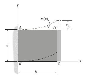
The rubber block is fixed along edge AB, and edge CD is moved so that the vertical displacement of any point in the block is given by v(x) = (vo/b3)x3. Determine the shear strain Yxy = 0.02 at points (b/2, a/2) and (b,a). a y A B -b. x C
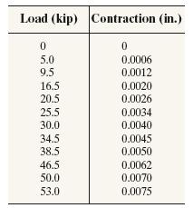
A concrete cylinder having a diameter of 6.00 in. and gauge length of 12 in. is tested in compression. The results of the test are reported in the table as load versus contraction. Draw the stress-strain diagram using scales of in. = 0.05 ksi and 1 in. = 0.2(10-3)in./in. From the diagram, determine
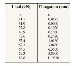
A tension test was performed on a steel specimen having an original diameter of 12.5mm and gage length of 50mm. Using the data listed in the table, plot the stress-strain diagram, and determine approximately the modulus of toughness. Use a scale of 20 mm = 50 MPa and 20 mm 0.05 mm/mm. Load (kN)
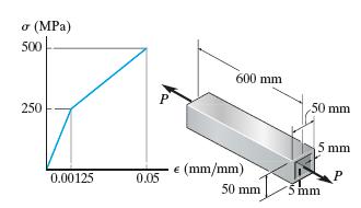
Determine the elongation of the square hollow bar when it is subjected to the axial force P = 100 kN. If this force is increased to P = 360 kN and released, find the permanent elongation of the bar. The bar is made of a metal alloy having a stress–strain diagram which can be approximated as
A structural member in a nuclear reactor is made of a zirconium alloy. If an axial load of 4 kip is to be supported by the member, determine its required cross-sectional area. Use a factor of safety of 3 relative to yielding. What is the load on the member if it is 3 ft long and its elongation is
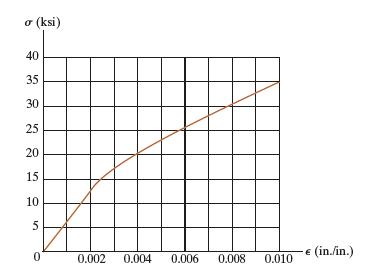
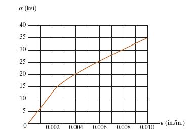
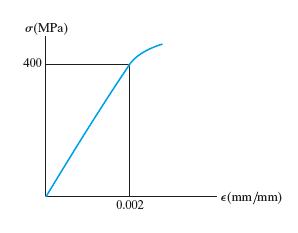
A tension test was performed on a magnesium alloy specimen having a diameter 0.5 in. and gauge length 2 in. The resulting stress–strain diagram is shown in the figure. Determine the approximate modulus of elasticity and the yield strength of the alloy using the 0.2% strain offset method. (ksi) 40
A tension test was performed on a magnesium alloy specimen having a diameter 0.5 in. and gauge length of 2 in.The resulting stress–strain diagram is shown in the figure. If the specimen is stressed to 30 ksi and unloaded, determine the permanent elongation of the specimen. (ksi) 40 35 30 25 20 15
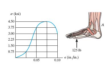
The σ - e diagram for a collagen fiber bundle from which a human tendon is composed is shown. If a segment of the Achilles tendon at A has a length of 6.5 in. and an approximate cross-sectional area of 0.229 in, determine its elongation if the foot supports a load of 125 lb, which causes a tension
The stress-strain diagram for many metal alloys can be described analytically using the Ramberg-Osgood three parameter equation ε= σ/E + kon, where E, k, and n are determined from measurements taken from the diagram. Using the stress-strain diagram shown in the figure, take E= 30(103) ksi and
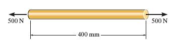
The acrylic plastic rod is 400 mm long and 20 mm in diameter. If an axial load of 500 N is applied to it, determine the change in its length and the change in its diameter.Ep = 1.85 GPa, vp = 0.45. 500 N 400 mm- 500 N
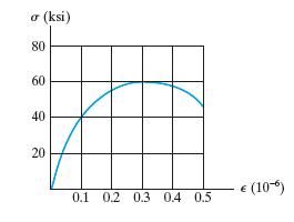
The elastic portion of the stress–strain diagram for a steel alloy is shown in the figure. The specimen from which it was obtained had an original diameter of 13 mm and a gauge length of 50 mm. When the applied load on the specimen is 50 kN, the diameter is 12.99265 mm. Determine Poisson’s
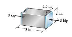
The aluminum block has a rectangular cross section and is subjected to an axial compressive force of 8 kip. If the 1.5-in. side changes its length to 1.500132 in., determine Poisson's ratio and the new length of the 2-in. side. Eal = 10(103) ksi. 8 kip 1.5 in. 2 in. 3 in.- 8 kip
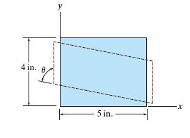
The block is made of titanium Ti-6A1-4V and is subjected to a shortening of 0.06 in. along the y axis, and its shape is given a tilt of θ =89.7. Determine εx, εy, and Yxy. 4 in. 8 A 5 in.
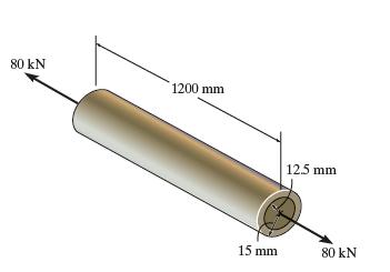
The thin-walled tube is subjected to an axial force of 80 kN.If the tube elongates 6.08 mm and its circumference decreases 0.167 mm, determine the modulus of elasticity, Poisson’s ratio, and the shear modulus of the tube’s material.The material behaves elastically. 80 kN 1200 mm 12.5 mm 15 mm
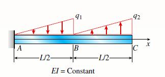
A cantilever beam has two triangular loads as shown in the figure.(a) Find an expression for beam deflection σC using superposition.(b) Find the required magnitude of load intensity q2 in terms of q1 so that the deflection at C is zero.(c) Find an expression for the deflection at C if both load
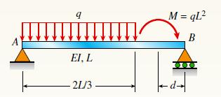
Find required distance d (in terms of L) so that rotation B = 0 is due to M and q loadings applied at the same time. Also, what is the resulting net rotation θA at support A? Moment M is applied at distance d from joint B. 9 EI, L -21/3 M =qL² B
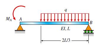
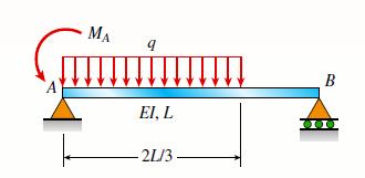
Find an expression for required moment MA (in terms of q and L) that will result in rotation θB = 0 due to MA and q loadings applied at the same time. Also, what is the resulting net rotation at support A? MA A q EI, L 21/3 B
Find an expression for the required moment MA (in terms of q and L) that will result in rotation θB = 0 due to MA and q loadings applied at the same time. Also, what is the resulting net rotation at support A? MA q EI, L 21/3 B
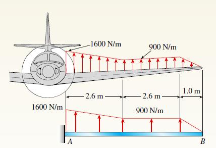
The wing of a small plane is represented by a simplified prismatic cantilever beam model acted on by the distributed loads shown in the figure. Assume constant EI =1200 kN.m2. Find the tip deflection and rotation at B. 1600 N/m A -1600 N/m 2.6 m 900 N/m -2.6 m- 900 N/m 1.0 m B
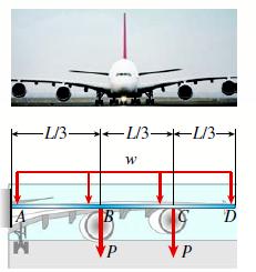
The wing of a large commercial jet is represented by a simplified prismatic cantilever beam model with uniform load w and concentrated loads P at the two engine locations (see figure). Find expressions for the tip deflection and rotation at D in terms of w, P, L, and EI. -L/3L/3L/3 P W P
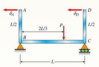
A framework ABCD is acted on by force P at 2L/3 from. Assume that EI is constant.(a) Find expressions for reactions at supports B and C.(b) Find expressions for angles of rotation at A, B, C, and D.(c) Find expressions for horizontal deflections σA and σD.(d) If length LAB = L / 2, find length
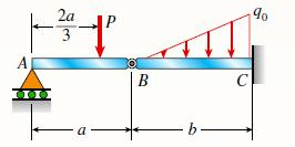
Compound beam ABC is loaded by point load P = 1.5 kips at a distance 2a/3 from point A and a triangularly distributed load on segment BC with peak intensity q0 = 0.5 kips/ft. If length a = ft and length b = 10 ft, find the deflection at B and rotation at A. Assume that E = 29,000 ksi and I = 53.8
Calculate the deflection at point C of a beam subjected to uniformly distributed load w = 275 N/m on span AB and point load P = 10 kN at C. Assume that L = 5 m and EI = 1.50 X 10⁷ N.m2. A W -L- B 000 가능 C
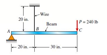
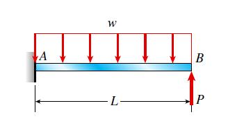
A steel beam ABC is simply supported at A and held by a high-strength steel wire at B. A load P = 240 lb acts at the free end C. The wire has axial rigidity EA = 1500 X 103 lb, and the beam has flexural rigidity EI = 36 X 106 lb-in2. What is the deflection σC of point C due to the load P? 20
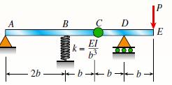
A compound beam ABCDE (see figure) consists of two parts (ABC and CDE) connected by a hinge (i.e., moment release) at C. The elastic support at B has stiffness k = EI / b3. Determine the deflection σE at the free end E due to the load P acting at that point. A 2b. B C D EI 9+9+9+ E
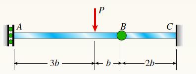
The compound beam ABC shown in the figure has a sliding support at A and a fixed support at C. The beam consists of two members joined by a pin connection (i.e., moment release) at B. Find the deflection σ under the load P. -3b- P B ·b* -b- -2b-
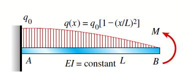
A cantilever beam is subjected to a quadratic distributed load q(x) over the length of the beam (see figure). Find an expression for moment M in terms of the peak distributed load intensity q0 so that the deflection is σB = 0. 90 A q(x) = qo[1-(x/L)²] El = constant L M B-
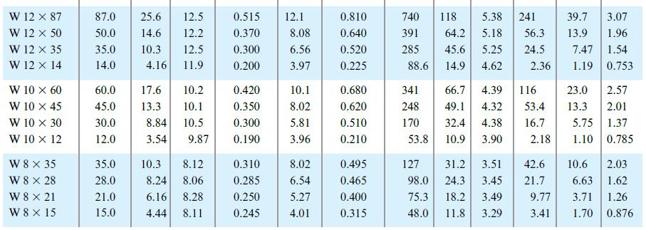
A simple beam with an overhang is subjected to a point load P = 6 kN. If the maximum allowable deflection at point C is 0.5 mm, select the lightest W 360 section from Table F-1(b) that can be used for the beam. Assume that L = 3 m and ignore the distributed weight of the beam Also, determine the
Repeat Problem 9.5-15 for the anti-symmetric loading shown in the figure.Staticsso reactions at A and B are equal and opposite but neither is equal to P (unlike symmetnc load case)Problem 9.5-15Use the method of superposition to find the angles of rotation θA and θB at the supports, and the
A cantilever beam has a length L = 12 ft and a rectangular cross-section (b = 16 in., h = 24 in.). A linearly varying distributed load with peak intensity q0 acts on the beam.(a) Find peak intensity q0 if the deflection at joint B is known to be 0.18 in. Assume that modulus E = 30,000 ksi.(b)
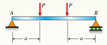
Use the method of superposition to find the angles of rotation θA and θB at the supports, and the maximum deflection θmax for a simply supported beam subjected to symmetric loads P at a distance a from each support. Assume that EI is constant, total beam length is L and a = L/3. A a |² P -
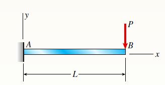
Derive the equation of the deflection curve for a cantilever beam AB when a couple of M0 acts counterclockwise at the free end (see figure). Also, determine the deflection σB and slope πB at the free end. Use the third-order differential equation of the deflection curve. -1- VB X
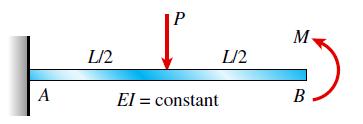
A cantilever beam is subjected to load P at mid-span and counterclockwise moment M at B (see figure).(a) Find an expression for moment M in terms of the load P so that the reaction moment MA at A is equal to zero.(b) Find an expression for moment M in terms of the load P so that the deflection is
Beams AB and CDE are connected using rigid link DB with hinges (or moment releases) at ends D and B (see figure a). Beam AB is fixed at joint A and beam CDE is pin-supported at joint E. Load P =150 lb is applied at C.(a) Calculate the deflections of joints B and joint C. Assume L = 9 ft and EI
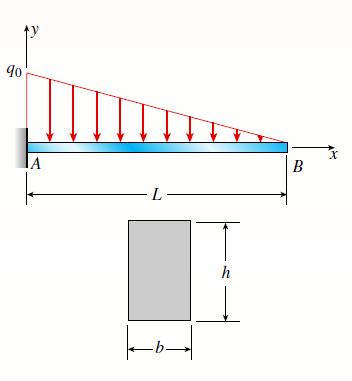
A cantilever beam carries a trapezoidal distributed load (see figure). Let wB = 2.5 kN/m, wA =.0 kN/m, and L = 2.5 m. The beam has a modulus E = 45GPa and a rectangular cross-section with width b = 200 mm and depth h = 300 mm. Use the method of superposition. Calculate the deflection and
A cantilever beam ACB supports two concentrated loads P1 and P2, as shown in the figure. Determine the deflections dC and dB at points C and B, respectively. P₁ C P2 B
A beam ABC with simple supports at A and B and an overhang BC supports a concentrated load P at the free end C.(a) Determine the strain energy U stored in the beam due to the load P.(b) From the strain energy, find the deflection dC under the load P.(c) Calculate the numerical values of U and σC
Beam ABC is loaded by a uniform load q and point load P at joint C. Using the method of superposition, calculate the deflection at joint C. Assume that L = 4 m, a = 2 m, q = 15 kN/m, P = 7.5 kN, E = 200 GPa, and I = 70.8 X 106 mm4. A q ↑↑↑↑↑↑↑ -L - --------| B a P C
Copper beam AB has a circular cross-section with a radius of 0.25 in. and length L = 3 ft. The beam is subjected to a uniformly distributed load w = 3.5 lb/ft. Calculate the required load P at joint B so that the total deflection at joint B is zero. Assume that E = 16,000 ksi. A W -L- B P
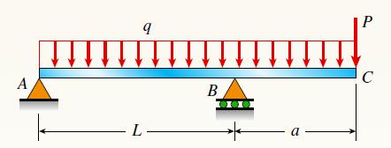
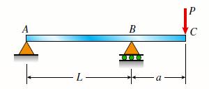
An overhanging beam ABC supports a concentrated load P at the end of the overhang. Span AB has length L, and the overhang has length a. Determine the deflection dC at the end of the overhang. A -7 L- B -a Ac
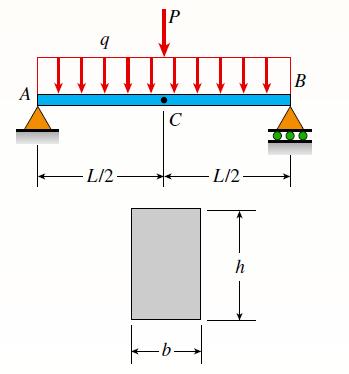
A simply supported beam (E = 12 GPa) carries a uniformly distributed load q = 125 N/m, and a point load P = 200 N at mid-span. The beam has a rectangular cross-section (b = 75 mm, h = 200 mm) and a length of 3.6 m. Calculate the maximum deflection of the beam. A 9 -L/2— Į C ko -L/2- h B
Showing 1200 - 1300
of 1529
First
2
3
4
5
6
7
8
9
10
11
12
13
14
15
16
Step by Step Answers